

Page 1

350-07/3650-07
Page 2

Page 3

Page 4

Page 5

Description
The CIa-VaI Model 100-01 Hytrol Valve is a main valve for
CIa-VaI Automatic Control Valves. It is a hydraulically operated,
diaphragm-actuated, globe or angle pattern valve.
This valve consists of three major components; body, diaphragm
assembly, and cover. The diaphragm assembly is the only
moving part. The diaphragm assembly uses a diaphragm of nylon
fabric bonded with synthetic rubber. A synthetic rubber disc,
contained on three and one half sides by a disc retainer and disc
guide, forms a seal with the valve seat when pressure is applied
above the diaphragm. The diaphragm assembly forms a sealed
chamber in the upper portion of the valve, separating operating
pressure from line pressure.
Installation
1. Before valve is installed, pipe lines should be flushed of all
chips, scale and foreign matter.
2. It is recommended that either gate or block valves be
installed on both ends of the 100-01 Hytrol Valve to facilitate
isoIating the valve for preventive maintenance and repairs.
3. Place the valve in the line with flow through the valve in the
direction indicated on the inlet nameplate. (See “Flow Direction”
Section)
4. Allow sufficient room around valve to make adjustments and
for disassembly.
5. CIa-VaI 100-01 Hytrol Valves operate with maximum effic iency
when mounted in horizontal piping with the cover UP, however,
other positions are acceptable. Due to size and weight of the
cover and internal components of 8 inch and larger valves,
installation with the cover UP is advisable. This makes internal
parts readily accessible for periodic inspection.
6. Caution must be taken in the installation of this valve to insure
that galvanic and/or electrolytic action does not take place. The
proper use of dielectric fittings and gaskets are required in all
systems using dissimilar metals.
7. If a pilot control system is installed on the 100-01 Hytrol Valve,
use care to prevent damage. If it is necessary to remove fittings
or components, be sure they are kept clean and replaced
exactly as they were.
8. After the valve is installed and the system is first pressurized,
vent air from the cover chamber and pilot system tubing by
loosening fittings at all high points.
Tight Closing Operation
When pressure from the valve inlet (or
an equivalent independent operating
pressure) is applied to the diaphragm
chamber the valve closes drip-tight.
Full Open Operation
When pressure in diaphragm chamber
is relieved to a zone of lower pressure
(usually atmosphere) the line pressure
(5 psi Min.) at the valve inlet opens the
valve.
Modulating Action
Valve modulates when diaphragm pressure is held at an intermediate point
between inlet and discharge pressure.
With the use of a Cla-Val. "modulating
control," which reacts to line pressure
changes, the pressure above the
diaphragm is varied, allowing the valve
to throttle and compensate for the
change.
Principles of Operation
Three Way
Pilot Control
Three Way
Pilot Control
Restriction
Modulating
Control
100-01
Hytrol Valve
MODEL
INSTALLATION / OPERATION / MAINTENANCE
Page 6

2
Flow Direction
The flow through the 100-01 Hytrol Valve can be in one of two
directions. When flow is “up-and-over the seat,” it is in “normal”
flow and the valve will fail in the open position. When flow is “overthe seat-and down,” it is in “reverse” flow and the valve will fail in
the closed position. There are no permanent flow arrow markings.
The valve must be installed according to nameplate data.
BRIDGEWALL INDlCATOR
Normal Flow Reverse Flow
Troubleshooting
The following troubleshooting information deals strictly with the
Model 100-01 Hytrol Valve. This assumes that all other components of the pilot control system have been checked out and are
in proper working condition. (See appropriate sections in
Technical Manual for complete valve).
Three Checks
The 100-01 Hytrol Valve has only one moving part (the diaphragm
and disc assembly). So, there are only three major types of problems to be considered.
First: Valve is stuck - that is, the diaphragm assembly is not free
to move through a full stroke either from open to close or vice
versa.
Second: Valve is free to move and can’t close because of a worn
out diaphragm.
Third: Valve leaks even though it is free to move and the
diaphragm isn’t leaking.
Closed isolation valves in control system, or in main line.
Lack of cover chamber pressure.
Diaphragm damaged. (See Diaphragm Check.)
Diaphragm assembly inoperative.
Corrosion or excessive scale build up on valve stem.
(See Freedom of Movement Check)
Mechanical obstruction. Object lodged in valve.
(See Freedom of Movement Check)
Worn disc. (See Tight Sealing Check)
Badly scored seat. (See Tight Sealing Check)
Closed upstream and/or downstream isolation
valves in main line.
Insufficient line pressure.
Diaphragm assembly inoperative. Corrosion or excessive
buildup on valve stem. (See Freedom of Movement Check)
Diaphragm damaged. (For valves in "reverse flow" only)
After checking out probable causes and remedies, the following three checks can be used to diagnose the nature of the
problem before maintenance is started. They must be done in the order shown.
Open Isolation valves.
Check upstream pressure, pilot system, strainer, tubing, valves, or needle
valves for obstruction.
Replace diaphragm.
Clean and polish stem. Inspect and replace any damaged or badly eroded
part.
Remove obstruction.
Replace disc.
Replace seat.
Open isolation valves.
Check upstream pressure. (Minimum 5 psi flowing line pressure differential.)
Clean and polish stem. Inspect and replace any
damaged or badly eroded part.
Replace diaphragm.
Fails to Close
Fails to Open
CAUTION:
Care should be taken when doing the troubleshooting checks on
the 100-01 Hytrol Valve. These checks do require the valve to
open fully. This will either allow a high flow rate through the
valve, or the downstream pressure will quickly increase to the
inlet pressure. In some cases, this can be very harmful. Where
this is the case, and there are no block valves in the system to
protect the downstream piping, it should be realized that the
valve cannot be serviced under pressure. Steps should be
taken to remedy this situation before proceeding any further.
(cast into side of valve body)
SYMPTOM PROBABLE CAUSE REMEDY
Recommended Tools
1. Three pressure gauges with ranges suitable to the installation to be put at Hytrol inlet, outlet and cover connections.
2. Cla-Val Model X101 Valve Position Indicator. This provides visual indication of valve position without disassembly
of valve.
3. Other items are: suitable hand tools such as screwdrivers, wrenches, etc. soft jawed (brass or aluminum) vise,
400 grit wet or dry sandpaper and water for cleaning.
All trouble shooting is possible without removing the valve from the
line or removing the cover. It is highly recommended to permanently
install a Model X101 Valve Position Indicator and three gauges in
unused Hytrol inlet, outlet and cover connections.
Page 7

Diaphragm Check (#1 )
1. Shut off pressure to the Hytrol Valve by slowly closing upstream
and downstream isolation valves. SEE CAUTION.
2. Disconnect or close all pilot control lines to the valve cover and
leave only one fitting in highest point of cover open to atmosphere.
3.With the cover vented to atmosphere, slowly open upstream
isolation valve to allow some pressure into the Hytrol Valve body.
Observe the open cover tapping for signs of continuous flow. It is
not necessary to fully open isolating valve. Volume in cover chamber capacity chart will be displaced as valve moves to open position. Allow sufficient time for diaphragm assembly to shift positions. If there is no continuous flow, you can be quite certain the
diaphragm is sound and the diaphragm assembly is tight. If the
fluid appears to flow continuously this is a good reason to believe
the diaphragm is either damaged or it is loose on the stem. In
either case, this is sufficient cause to remove the valve cover and
investigate the leakage. (See “Maintenance” Section for procedure.)
Freedom of Movement Check (#2)
4. Determining the Hytrol Valve’s freedom of movement can be
done by one of two methods.
5. For most valves it can be done after completing Diaphragm
Check (Steps 1, 2, and 3). SEE CAUTION. At the end of step 3
the valve should be fully open.
6. If the valve has a Cla-Val X101 Position Indicator, observe the
indicator to see that the valve opens wide. Mark the point of maximum opening.
7. Re-connect enough of the control system to permit the application of inlet pressure to the cover. Open pilot system cock so
pressure flows from the inlet into the cover.
8. While pressure is building up in the cover, the valve should
close smoothly. There is a hesitation in every Hytrol Valve closure,
which can be mistaken for a mechanical bind. The stem will
appear to stop moving very briefly before going to the closed position. This slight pause is caused by the diaphragm flexing at a
particular point in the valve’s travel and is not caused by a
mechanical bind.
9. When closed, a mark should be made on the X101 Valve position indicator corresponding to the “closed” position. The distance
between the two marks should be approximately the stem travel
shown in chart.
10. If the stroke is different than that shown in stem travel chart
this is a good reason to believe something is mechanically restricting the stroke of the valve at one end of its travel. If the flow does
not stop through the valve when in the indicated “closed” position,
the obstruction probably is between the disc and the seat. If the
flow does stop, then the obstruction is more likely in the cover. In
either case, the cover must be removed, and the obstruction located and removed. The stem should also be checked for scale buildup. (See “Maintenance, section for procedure.)
11. For valves 6” and smaller, the Hytrol Valve’s freedom of movement check can also be done after all pressure is removed from
the valve. SEE CAUTION. After closing inlet and outlet isolation
valves and bleeding pressure from the valve, check that the cover
chamber and the body are temporarily vented to atmosphere.
Insert fabricated tool into threaded hole in top of valve stem, and
lift the diaphragm assembly manually. Note any roughness. The
diaphragm assembly should move smoothly throughout entire
valve stroke. The tool is fabricated from rod that is threaded on
one end to fit valve stem and has a “T” bar handle of some kind
on the other end for easy gripping. (See chart in Step 4 of
“Disassembly” Section.)
12. Place marks on this diaphragm assembly lifting tool when the
valve is closed and when manually positioned open. The distance
between the two marks should be approximately the stem travel
shown in stem travel chart. If the stroke is different than that
shown, there is a good reason to believe something is mechanically restricting the stroke of the valve. The cover must be
removed, and the obstruction located and removed. The stem
should also be checked for scale build-up. (See “Maintenance”
Section for procedure.)
Tight Sealing Check (#3)
13. Test for seat leakage after completing checks #1 & #2 (Steps
1 to 12). SEE CAUTION. Close the isolation valve downstream of
the Hytrol Valve. Apply inlet pressure to the cover of the valve, wait
until it closes. Install a pressure gauge between the two closed
valves using one of the two ports in the outlet side of the Hytrol.
Watch the pressure gauge. If the pressure begins to climb, then
either the downstream isolation valve is permitting pressure to
creep back, or the Hytrol is allowing pressure to go through it.
Usually the pressure at the Hytrol inlet will be higher than on the
isolation valve discharge, so if the pressure goes up to the inlet
pressure, you can be sure the Hytrol is leaking. Install another
gauge downstream of isolating valve. If the pressure between the
valves only goes up to the pressure on the isolation valve
discharge, the Hytrol Valve is holding tight, and it was just the isolation valve leaking.
STEM TRAVEL
(Fully Open to Fully Closed)
Valve Size (inches) Travel (inches)
Inches MM Inches MM
1 1/4 32 0.4 10
1 1/2 40 0.4 10
250 0.615
2 1/2 65 0.7 18
380 0.820
4 100 1.1 28
6 150 1.7 43
8 200 2.3 58
10 250 2.8 71
12 300 3.4 86
14 350 4.0 100
16 400 4.5 114
20 500 5.6 143
24 600 6.7 165
30 800 7.5 190
36 900 8.5 216
COVER CHAMBER CAPACITY
(Liquid Volume displaced when valve opens)
Valve size (inches) Displacement
Gallons Liters
1 1/4 .020 .07
1 1/2 .020 .07
2 .032 .12
2 1/2 .043 .16
3 .080 .30
4 .169 .64
6 .531 2.0
8 1.26 4.8
10 2.51 9.5
12 4.00 15.1
14 6.50 24.6
16 9.57 36.2
20 12.00 45.4
24 29.00 109.8
30 42.00 197.0
36 90.00 340.0
3
Page 8
Maintenance
Preventative Maintenance
The Cla-Val Co. Model 100-01 Hytrol Valve requires no lubrication or
packing and a minimum of maintenance. However, a periodic inspection schedule should be established to determine how the operating
conditions of the system are affecting the valve. The effect of these
actions must be determined by inspection.
Disassembly
Inspection or maintenance can be accomplished without removing
the valve from the line. Repair kits with new diaphragm and disc are
recommended to be on hand before work begins.
WARNING: Maintenance personnel can be injured and equipment
damaged if disassembly is attempted with pressure in the valve. SEE
CAUTION.
1. Close upstream and downstream isolation valves and independ-
ent operating pressure when used to shut off all pressure to the
valve.
2. Loosen tube fittings in the pilot system to remove pressure from
valve body and cover chamber. After pressure has been released
from the valve, use care to remove the controls and tubing. Note and
sketch position of tubing and controls for re-assembly. The schematic in front of the Technical Manual can be used as a guide when
reassembling pilot system.
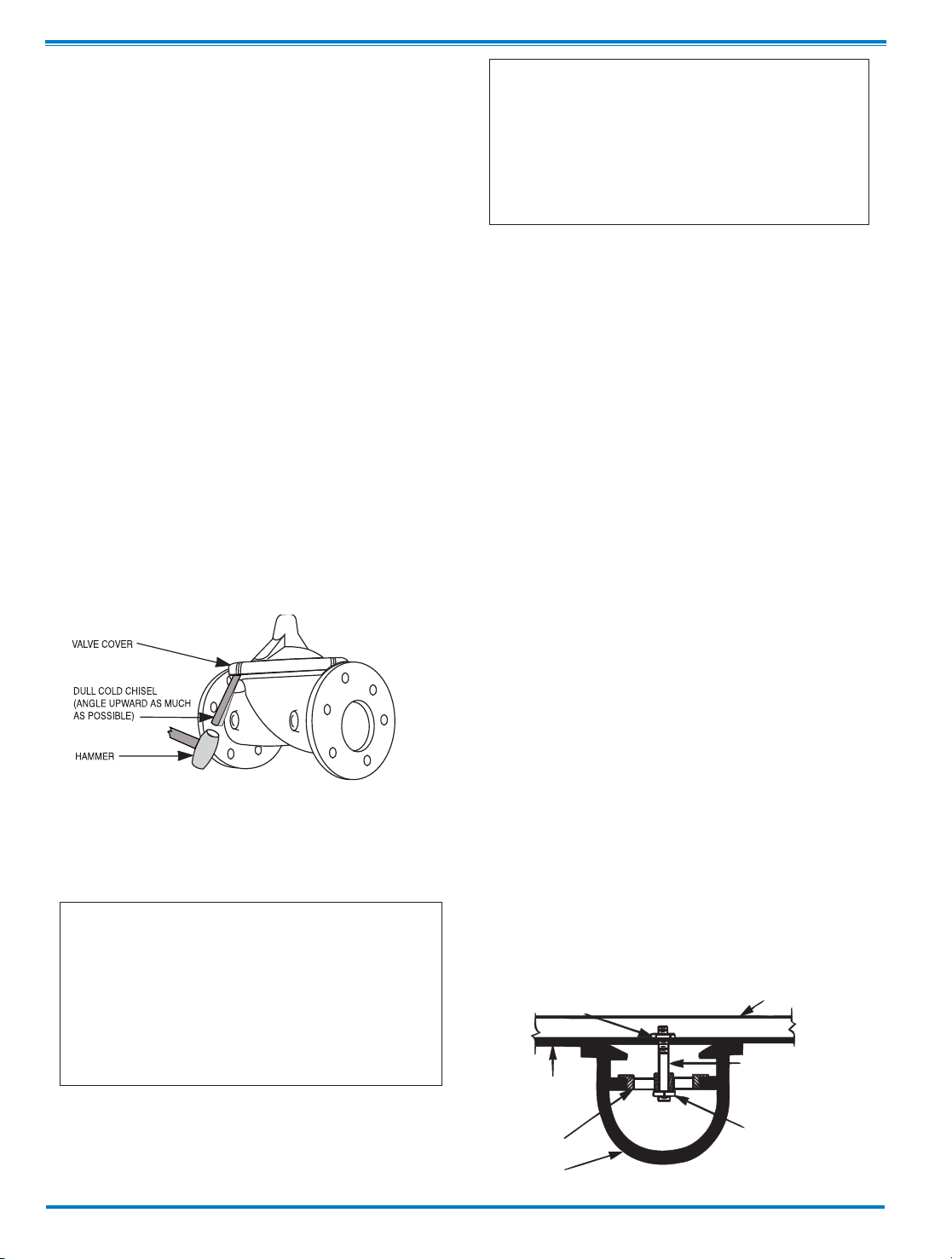
3. Remove cover nuts and remove cover. If the valve has been in
service for any length of time, chances are the cover will have to be
loosened by driving upward along the edge of the cover with a dull
cold chisel.
On 6” and smaller valves block and tackle or a power hoist can be
used to lift valve cover by inserting proper size eye bolt in place of
the center cover plug. on 8” and larger valves there are 4 holes (5/8”
— 11 size) where jacking screws and/or eye bolts may be inserted
for lifting purposes. Pull cover straight up to keep from damaging
the integral seat bearing and stem.
4. Remove the diaphragm and disc assembly from the valve body.
With smaller valves this can be accomplished by hand by pulling
straight up on the stem so as not to damage the seat bearing.
On large valves, an eye bolt of proper size can be installed in the
stem and the diaphragm assembly can be then lifted with a block and
tackle or power hoist. Take care not to damage the stem or bearings.
The valve won't work if these are damaged.
5. The next item to remove is the stem nut. Examine the stem
threads above the nut for signs of mineral deposits or corrosion.
If the threads are not clean, use a wire brush to remove as much
of the residue as possible. Attach a good fitting wrench to the nut
and give it a sharp “rap” rather than a steady pull. Usually
several blows are sufficient to loosen the nut for further removal.
On the smaller valves, the entire diaphragm assembly can be held
by the stem in a vise equipped with soft brass jaws before
removing the stem nut.
The use of a pipe wrench or a vise without soft brass jaws scars
the fine finish on the stem. No amount of careful dressing can
restore the stem to its original condition. Damage to the finish of
the stem can cause the stem to bind in the bearings and the valve
will not open or close.
6. After the stem nut has been removed, the diaphragm assembly
breaks down into its component parts. Removal of the disc from
the disc retainer can be a problem if the valve has been in service for a long time. Using two screwdrivers inserted along the outside edge of the disc usually will accomplish its removal. Care
should be taken to preserve the spacer washers in water, particularly if no new ones are available for re-assembly.
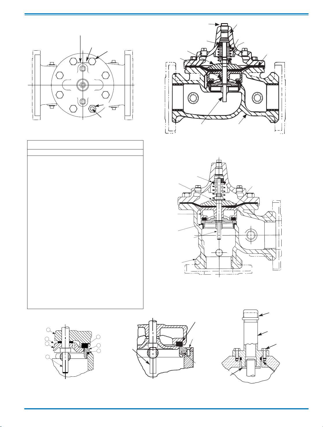
7. The only part left in the valve body is the seat which ordinarily
does not require removal. Careful cleaning and polishing of inside
and outside surfaces with 400 wet/dry sandpaper will usually
restore the seat’s sharp edge. If, however, it is badly worn and
replacement is necessary, it can be easily removed.
Seats in valve sizes 1 1/4” through 6” are threaded into the valve
body. They can be removed with accessory X109 Seat Removing
Tool available from the factory. On 8” and larger valves, the seat
is held in place by flat head machine screws. Use a tight-fitting,
long shank screwdriver to prevent damage to seat screws. If upon
removal of the screws the seat cannot be lifted out, it will be necessary to use a piece of angle or channel iron with a hole drilled
in the center. Place it across the body so a long stud can be inserted through the center hole in the seat and the hole in the angle
iron. By tightening the nut a uniform upward force is exerted on
the seat for removal.
NOTE: Do not lift up on the end of the angle iron as this may force
the integral bearing out of alignment, causing the stem to bind.
VALVE STEM THREAD SIZE
Valve Size Thread Size (UNF Internal)
1 1/4"
—2 1/2" 10—32
3"—4" 1/4—28
6"—14" 3/8—24
16" 1/2—20
20 3/4-16
24" 3/4-16
30” 3/4-16
36” 3/4-16
COVER CENTER PLUG SIZE
Valve Size Thread Size (NPT)
1 1/4"
—1 1/2" 1/4"
2"—3" 1/2"
4"—6" 3/4"
8"—10" 1"
12" 1 1/4"
14" 1 1/2"
16" 2"
20” & 24" 2"
30” & 36” 2”
NUT
ANGLE OR CHANNEL IRON
LONG STUD OR BOLT
NUT OR BOLT HEAD
DO NOT
LIFT
VALVE SEAT
VALVE BODY
4
Page 9

Lime Deposits
One of the easiest ways to remove lime deposits from the valve
stem or other metal parts is to dip them in a 5-percent muriatic
acid solution just long enough for the deposit to dissolve. This
will remove most of the common types of deposits. CAUTlON:
USE EXTREME CARE WHEN HANDLING ACID. Rinse parts in
water before handling. If the deposit is not removed by acid, then
a fine grit (400) wet or dry sandpaper can be used with water.
Reassembly
1. Reassembly is the reverse of the disassembly procedure. If a
new disc has been installed, it may require a different number of
spacer washers to obtain the right amount of “grip” on the disc.
When the diaphragm assembly has been tightened to a point
where the diaphragm cannot be twisted, the disc should be compressed very slightly by the disc guide. Excessive compression
should be avoided. Use just enough spacer washers to hold the
disc firmly without noticeable compression.
2. MAKE SURE THE STEM NUT IS VERY TIGHT. Attach a good
fitting wrench to the nut and give it a sharp “rap” rather than a
steady pull. Usually several blows are sufficient to tighten the
stem nut for final tightening. Failure to do so could allow the
diaphragm to pull loose and tear when subjected to pressure.
Test Procedure After Valve Assembly
There are a few simple tests which can be made in the field to
make sure the Hytrol Valve has been assembled properly. Do
these before installing pilot system and returning valve to
service. These are similar to the three troubleshooting tests.
1. Check the diaphragm assembly for freedom of movement
after all pressure is removed from the valve. SEE CAUTlON.
Insert fabricated tool into threaded hole in top of valve stem, and
lift the diaphragm assembly manually. Note any roughness,
sticking or grabbing. The diaphragm assembly should move
smoothly throughout entire valve stroke. The tool is fabricated
from rod that is threaded on one end to fit valve stem (See chart
in Step 4 of “Disassembly” section.) and has a “T” Bar handle of
some kind on the other end for easy gripping.
Place marks on this diaphragm assembly lifting tool when the
valve is closed and when manually positioned open. The distance between the two marks should be approximately the stem
travel shown in stem travel chart. (See “Freedom of Movement
Check” section.) If the stroke is different than that shown, there
is a good reason to believe something is mechanically restricting
the stroke of the valve. The cover must be removed, the obstruction located and removed. (See “Maintenance” Section for
procedure.)
Inspection of Parts
After the valve has been disassembled, each part should be
examined carefully for signs of wear, corrosion, or any other
abnormal condition. Usually, it is a good idea to replace the rubber parts (diaphragm and disc) unless they are free of signs of
wear. These are available in a repair kit. Any other parts which
appear doubtful should be replaced. WHEN ORDERlNG
PARTS, BE SURE TO GIVE COMPLETE NAMEPLATE DATA,
ITEM NUMBER AND DESCRlPTlON.
NOTE: If a new disc isn’t available, the existing disc can be
turned over, exposing the unused surface for contact with the
seat. The disc should be replaced as soon as practical.
3. Carefully install the diaphragm assembly by lowering the stem
through the seat bearing. Take care not to damage the stem or
bearing. Line up the diaphragm holes with the stud or bolt holes
on the body. on larger valves with studs, it may be necessary to
hold the diaphragm assembly up part way while putting the
diaphragm over the studs.
4. Put spring in place and replace cover. Make sure diaphragm
is Iying smooth under the cover.
5. Tighten cover nuts firmly using a cross-over pattern until all
nuts are tight.
6. Test Hytrol Valve before re-installing pilot valve system.
Due to the weight of the diaphragm assembly this procedure is
not possible on valves 8” and larger. on these valves, the same
determination can be made by carefully introducing a low
pressure-less than five psi) into the valve body with the cover
vented. SEE CAUTION. Looking in cover center hole see the
diaphragm assembly lift easily without hesitation, and then
settle back easily when the pressure is removed.
2. To check the valve for drip-tight closure, a line should be
connected from the inlet to the cover, and pressure applied at the
inlet of the valve. If properly assembled, the valve should hold
tight with as low as ten PSI at the inlet. See “Tight Sealing
Check” section.)
3. With the line connected from the inlet to the cover, apply full
working pressure to the inlet. Check all around the cover for any
leaks. Re-tighten cover nuts if necessary to stop leaks past the
diaphragm.
4. Remove pressure, then re-install the pilot system and tubing
exactly as it was prior to removal. Bleed air from all high
points.
5. Follow steps under “Start-Up and Adjustment” Section in
Technical Manual for returning complete valve back to service
.
5
Page 10
1
5
8
10
14
16
6
17
7
9
OUTLE
T
INLET
GLOBE PATTERN
9
26
27
12
15
14
16
INLET
OUTLET
ANGLE PATTERN
22
23
13
12
14
10
11
15
23
TOP VIEW
8" - 24" SEAT DETAIL
1 1/4" - 6" SEAT DETAIL
16" COVER DETAIL
4
24
2
25
13
31
28
30
29
5
14
3
Item Description
1. Pipe Plug
2. Drive Screws (for nameplate)
3. Hex Nut (8” and larger)
4. Stud (8” and larger)
5. Cover Bearing
6. Cover
7. Stem Nut
8. Diaphragm Washer
9. Diaphragm
10. Spacer Washers
11. Disc Guide
12. Disc Retainer
13. Disc
14. Stem
15. Seat
16. Body
17. Spring
22. Flat Head Screws (8” and larger)
23. Seat O-Ring
24. Hex head Bolt (1 1/4” thru 4”)
25. Nameplate
26. Upper Spring Washer (Epoxy coated valves only)
27. Lower Spring Washer (Epoxy coated valves only)
28. Cover Bearing Housing (16” only)
29. Cover O-Ring (16’” only)
30. Hex Bolt (16” only)
31. Pipe Cap (16” only)
PARTS LIST
6
Page 11

100-01
Hytrol Valve Service Data
MODEL
INSTALLATION / OPERATION / MAINTENANCE
Description 100-01 Hytrol Valve
The CIa-VaI Model 100-01 Hytrol Valve is a main valve for
CIa-VaI Automatic Control Valves. It is a hydraulically operated,
diaphragm-actuated, globe or angle pattern valve.
This valve consists of three major components; body, diaphragm
assembly, and cover. The diaphragm assembly is the only
moving part. The diaphragm assembly uses a diaphragm of nylon
fabric bonded with synthetic rubber. A synthetic rubber disc,
contained on three and one half sides by a disc retainer and disc
guide, forms a seal with the valve seat when pressure is applied
above the diaphragm. The diaphragm assembly forms a sealed
chamber in the upper portion of the valve, separating operating
pressure from line pressure.
Description 100-20 600 Series Hytrol Valve
The CIa-VaI Model 100-20 Hytrol Valve (600 Series main valve)
have only one part -the body- that is different from standard 100
Series Cla-Val main valve parts. The remaining parts of the 600
series main valve are standard Cla-Val main valve parts. All serv-
ice and maintenance information for the standard 100 Series
main valves also apply to the 600 series main valves.
The most important thing to remember when ordering main
valve repair kits and replacement parts, except for the body, all
other parts are going to be for a smaller size main valve. Cla-
Val identifies main valve parts with the flange size of the stan-
dard 100 Series main valve. Refer to the "Main Valve Sizes”
chart below.
HYTROL Service Data
HYTROL SIZE
Stem
Travel
Cover Capacity
Displacement
Valve Stem
Thread
UNF-Internal
Cover
Center
Plug
NPT
Cover Nut or Bolt
Cover
Lifting
Holes
UNC
Cover Plug Cover Torque
Stem Nut**
Stem Nut Torque
(ft. Lbs.)
100-01
100-20
Thread
(Bolt)
Socket
Qty Thread
Socket ft. Lbs. in. Lbs.
Thread
Socket
(Long)
inches mm inches mm inches mm
Gallons
Liters
Lubed DRY
1"
25 0.3 8 1/4"
1/4" - 20 (B)
7/16" 8
4
48 3/8" - 24
4
6
1 1/4"
32
0.4
10
0.020
0.07
10 - 32
1/4" 5/16" - 18 (B) 1/2"
8
8 96 7/16" -20 6 10
1 1/2" 40 0.4 10 0.020 0.07
10 - 32
1/4" 5/16" - 18 (B) 1/2"
8
8 96 7/16" -20 6 10
2" 50 0.6 15 0.032
0.12 10 - 32
1/2" 3/8" - 16 (B) 9/16" 8 3/8" 7/16" 12
1/2" - 20
3/4" 10 15
2 1/2"
65 0.7 18
0.043 0.16
10 - 32
1/2" 7/16" - 14 (B) 5/8" 8 1/2" 9/16" 20
5/8" - 18 15/16" 21
30
3" 80 4" 100 0.8
20
0.080 0.30
1/4 - 28 1/2"
1/2" - 13 (B)
3/4" 8 1/2" 9/16" 30 5/8" - 18
15/16"
21 30
4" 100 6" 150 1.1 23
0.169 0.64
1/4 - 28 3/4"
3/4" - 10 (B)
1 1/8" 8 3/4" 5/8" 110 3/4" - 16
1 1/16"
40
60
6" 150 8" 200 1.7 43 0.531 2.00 3/8 - 24 3/4"
3/4" - 10 (B) 1 1/8"
12 3/4"
5/8" 110
7/8" - 14
1 5/16"
85 125
8"
200 10"
250
2.3 58
1.26 4.80 3/8 - 24
1"
3/4" - 10
1 1/4" 16 5/8" - 11
1" 13/16" 110
1 1/8" -12 1 13/16"
125
185
10" 250 12" 300 2.8 71 2.51 9.50
3/8 - 24
1" 7/8" - 9 1 7/16"
20
3/4" - 10
1"
13/16" 160 1 1/2" -12 1 7/8" 252 375
12" 300 16" 400 3.4 86 4.0 15.10
3/8 - 24
1 1/4" 1 1/8" - 7 1 13/16"
20
3/4" - 10
1" 13/16" 390 1 1/2" -12 2 1/2" 270 400
14" 350 3.9
99
6.5
24.60
3/8 - 24 1 1/2" 1 1/4" - 7
2" 20
1" - 8
1" 13/16" 545 1 1/2" -12
2 1/2"
280 420
16"
400
20", 24"
600
4.5
114
9.6 36.20
1/2 - 20
2" 1 1/4" - 7
2" 20
1" - 8
1" 13/16" 545 2" - 16 3" 500 750
20" 500 5.63
143
12 45.40
3/4 - 16 1 1/2" 1 3/8" - 6
2 1/8" 24
1" - 8
1" 13/16" 670
2 1/4" - 16
3 1/2" 930
N/R
24" 600
30"
800 6.75 165
29.0
108.80 3/4 - 16*
3/4"
1 1/2" - 12 2 3/8" 24
1 1/8"- 7
1" 13/16"
800
3" - 12
Special
1350
N/R
* Adapter
p/n 2594101E
inside 1/4" - 28"
Grade 5 Bolts
"Heavy" Grade Nuts
Tighten cover nuts in a "star" cross-over pattern
** Must Use ONLY
Cla-Val Supplied part
Page 12

COVER
PIPE PLUG
COVER BEARING
SPRING
STEM NUT
DIAPHRAGM WASHER
DISC RETAINER
BODY
*
SPACER WASHERS
DISC GUIDE
SEAT
PIPE PLUG
STEM
SEAT O-RING
STUD
8" and Larger
*
DIAPHRAGM
*
DISC
*
Repair Parts
Seat Screw
8" and Larger
(Globe
or
Angle)
PIPE PLUG
HEX NUT
8" and Larger
Cover Bolt
6" and Smaller
KO
DISC GUIDE
KO
SEAT
KO Anti-Cavitation
Trim Option
N-100-01 (R-3/2011
CLA-VAL
Copyright Cla-Val 2011 Printed in USA Specifications subject to change without notice.
P.O. Box 1325 • Newport Beach, CA 92659-0325 • Phone: 949-722-4800 • Fax: 949-548-5441 • E-mail: claval@cla-val.com • Website cla-val.com
©
BOLT/NUT TORQUING PROCEDURES ON VALVE COVERS
4
BOLTS
6
BOLTS
8
BOLTS
12
BOLTS
16
BOLTS
20
BOLTS
4
3
2
1
65
4
3
2
1
8
7
6
5
4
3
2
1
0
9
8
7
6
5
4
3
2
1
12
11
10
9
8
7
6
5
4
3
2
1
16
15
14
13
12
11
10
9
8
7
6
5
4
3
2
1
20
19
18
17
16
15
14
13
12
11
Follow this procedure when reassembling MAIN Valve:
1. Tightens bolts/nuts in a “Star” or “Cross-Over” pattern following the
numbers shown above to insure that cover seats evenly on the diaphragm
material and body.
2. Torque the bolt/nuts in three stages with a "Star" or "Cross-Over" pattern
for each stage:
A. To approximately 10% of final torque.
B. To approximately 75% of final torque.
C. To final required torque.
3. Valves that are to be tested to 375 PSI or higher should be retorqued
after 24 hours.
100-01 Hytrol Main Valve Assembly
Page 13

UNDERSTANDING THE 600 SERIES VALVES
In 1987, Cla-Val introduced the Model 100-20 Hytrol as the basic
main valve for the 600 Series of automatic control valves. To
identify all new valves using the 100-20 Hytrol, an existing catalog number is modified. Making a 600 Series catalog number is
simply done by using a "6" in front of the two digit catalog numbers or replacing the "2" with a "6" in three digit catalog numbers. Current schematics reflect both catalog numbers together
separated by a slash ( i.e. - 90-01/690-01, 58-02/658-02, 21001/610-01, etc). Since these two valves 'share' the same catalog
number and schematic, they provide the same function in a system. The only difference between the two valves is the relative
capacity of the two main valve series.
The 100-01 Hytrol is the basic main valve for Cla-Val automatic
control valves. This valve is the current version of the Clayton
Hytrol valve design originated in 1936. The 100-01 Hytrol is
designed as a full flow area valve. This means that the inlet,
seat and outlet openings are the same size. Thus, the pressure
drop is kept to a minimum for this globe style design.
The 100-20 Hytrol valve has all of the basic features and advantages of the original 100-01 Hytrol. Only one part has been
changed - the body. It is designed with different size inlet, seat
and outlet openings. The 100-20 Hytrol has inlet and outlet
flanges one valve size larger than the seat opening size. This
results in what is sometimes called a ''reduced port' main valve.
For example, a 4" 100-20 valve has a 3" seat. Note: valve size
is always determined by the flange size. The following chart
compares the 100-01 and the 100-20 main valves.
600 Series Hytrol Valve
100-20
MODEL
INSTALLATION / OPERATION / MAINTENANCE
SERVICE AND MAINTENANCE OF 600 SERIES
VALVES
The 600 series main valves have only one part -the body- that is
different from standard 100 Series Cla-Val main valve parts. The
remaining parts of the 600 series main valve are standard ClaVal main valve parts. All service and maintenance information
for the standard 100 Series main valves in this manual also
apply to the 600 series main valves.
The most important thing to remember when ordering main valve
repair kits and replacement parts, except for the body, all other
parts are going to be for a smaller size main valve. Cla-Val identifies main valve parts with the flange size of the standard 100
Series main valve. Refer to the "Main Valve Sizes Comparison"
chart. For example, if you are servicing a 6" 100-20 Hytrol and
needed a repair kit, you would order a repair kit for a 4" 100-01
Hytrol. This kit is also suitable for a 6" 100-20 Hytrol. Complete
Technical Manuals include a repair kit data sheet N-RK that
shows this relationship.
When you order repair parts, it is a good idea to include valve
nameplate data (size, catalog number, and part number) and
description of the parts desired. Do this to be sure parts will fit
the valve you are working on and not be too big for it. Pilot controls and repair kits maintenance information remain the same
for 100 or 600 Series valves.
Cla-Val Main Valves
Catalog Number
The 100-20 Hytrol is available only in ductile iron, 150 and 300
pressure class, and Bronze trim standard. Available extra cost
main valve options include stainless steel trim, epoxy coating,
Dura-Kleen stem, Delrin sleeved stem, and high temperature rubber parts. All four basic main valves have a 600 Series version
available with all of the same benefits and size relationships.
The following chart shows the relationship of Cla-Val main valve
catalog numbers.
Catalog Name
Hytrol
Powertrol
Powercheck
Hycheck
Circa 1936
100 (Angle =2100)
100P & 100PA
100PC & 100PCA
181
100-Series
100-01
100-02
100-03
100-04
600 Series
100-20
100-21
100-22
100-23
(Reduced Internal Port)
Basic Main Valve Size Comparison
Globe Pattern Valves
Flange Size (inch)
Seat Size
100-01 (100 Series) 100-20 (600 Series)
3 3 2
4 4 3
6 6 4
8 8 6
10 10 8
12 12 10
14 14 ---16 16 12
18 ---- 16
20 20 16
24 24 16
30 30 24
36 36 30
42 ---- 36
48 ---- 36
Angle Pattern Valves
Flange Size (inch)
Seat Size
100-01 (100 Series) 100-20 (600 Series)
4 4 3
6 6 4
8 8 6
Page 14

CLA-VAL
Copyright Cla-Val 2011 Printed in USA Specifications subject to change without notice.
P.O. Box 1325 • Newport Beach, CA 92659-0325 • Phone: 949-722-4800 • Fax: 949-548-5441 • E-mail: claval@cla-val.com • Website cla-val.com
©
N-100-20 (R-3/2011)
100-20
PARTS LIST
NO. DESCRIPTION
1 Pipe Plug
2 Drive Screws (for nameplate)
3 Hex Nut (8" and larger)
4 Stud (8" and larger)
5 Cover Bearing
6 Cover
7 Stem Nut
8 Diaphragm Washer
9 Diaphragm
10 Spacer Washers
11 Disc Guide
12 Disc Retainer
13 Disc
14 Stem
15 Seat
16 Body
17 Spring
22 Flat Head Screws (10" and larger)
23 Seat O-Ring
24 Hex Bolt (3 " Thru 6")
25 Nameplate (Mounted on inlet flange)
26 Upper Spring Washer (Epoxy coated valves only)
27 Lower Spring Washer (Epoxy coated valves only)
28 Cover Bearing Housing (20" & 24" & 30")
29 Cover Bearing Housing O-Ring (20"& 24" & 30")
30 Hex Bolt (20" & 24")
31 Pipe Cap (20" & 24 & 30"")
11
14
12434
5
17
16
26
14
7
8
9
27
14
13
22
12
15
31
28
5
30
29
10" — 24" SEAT DETAIL
20" — 24" COVER DETAIL
TOP VIEW
12
13
15
OUTLET
GLOBE
INLET
ANGLE
INLET
6
8
9
2
25
3" — 6" COVER DETAIL
23
11
WHEN ORDERING PARTS, BE SURE TO GIVE COMPLETE
NAMEPLATE DATA, ITEM NUMBER AND DESCRIPTION.
10
Page 15

RDH051228,TB_300-SingleModeControls32.doc,6/16/2006
Technical Bulletin
300 Series (Single-Mode) Electronic Actuated Pilot Controls
Introduction
CDB-32, CDHS-32, CRA-32, CRD-32, and CRL-32 are pilot controls for Cla-Val 300 Series Electronic Actuated
Control Valves. These controls offer the same hydraulic control of the valve as existing manually-set controls, along
with additional remote electronic setpoint adjustment capabilities. The new pilot controls consist of a modified pilot
control sub-assembly, and the 130VC-2 Electronic Actuator with mounting components. Complete controls are valve
mounted with an accessory X56 Mounting Assembly.
I. O. M. Information
A. The 130VC-2 wiring diagram is included with this technical bulletin. The 5-wire cable is permanently attached to
actuator and should be terminated in suitable junction box. Care should be used when attaching to wires to avoid
damage. There are no user serviceable parts inside the actuator and tampering or opening it will void the warranty.
B. For Installation, Operation and Maintenance information only on the pilot sub-assembly use instructions in the
appropriate N-sheet for the manually adjusted pilot control. Since the 130VC-2 Electronic Actuator changes the
setpoint adjustment of the control, all other service and maintenance information remains the same for both. See
table below.
C. Additional service notes:
1. Before disassembly of pilot subassembly from 130VC-2 actuator, adjust pilot control to full minimum range setting
with laptop computer and 130VC-2 software to ensure full adjustment range when reassembled.
2. Note orientation of sub-assembly ports and bracket. Coupler and blue Aluminum bracket will remain attached to
actuator. Loosen and remove jam nut and washer from sub-assembly cover as sub-assembly is removed from
130VC-2 bracket. Count number of turns counterclockwise of pilot adjustment shaft from minimum range set position
to full out stop position. See pilot drawing.
3. After servicing the pilot sub-assembly, re-establish minimum spring setting by manually turning adjusting screw
counterclockwise until it stops (full out stop position). Then, turn in same number of turns found in step 2 to minimum
range set position.
4. Do not lubricate coupler slots. A small amount of waterproof anti-seize grease is used only on sub-assembly
adjusting screw threads and contact point with spring guide inside cover.
5. Reinstall sub-assembly to bracket with jam nut and washer. Check coupler slots and adjusting screw pin are lined
up while installing actuator to bracket. Be sure to retain original alignment of sub-assembly with bracket when
tightening jam nut and washer. A slight manual adjustment of adjusting screw may help align the coupler to adjusting
screw. See pilot assembly drawing.
6. After reinstalling onto valve, use laptop computer and 130VC-2 software to reset range values.
Pilot Control Pilot Assembly
Drawing
Sub-Assembly
IOM (ref. only)
Sub-Assembly
Drawing
Sub-Assembly
Repair Kit
CDB-32 205580 N-CDB-7 201935 9170023H
CDHS-32 205137 N-CDHS-11A 76832 20287401E
CDHS-32A 205333 N-CDHS-11B 205332 9170028G
CRA-32 N-CRA 82528 9170001D
CRD-32 205129 N-CRD 70899 9170002B
CRL-32 205130 N-CRL-5A 90846 20666E
Page 16

•
Simplified Remote Valve Set-Point Control
•
12-24VDC Input Power
•
Easy Interfacing to SCADA Systems
•
Accurate Pressure Control
•
Reliable Hydraulic Operation
•
Submersible (IP-68)
The Cla-Val Model CRL-32 Electronic Actuated Pressure Sustaining Pilot
Control provides remote set-point adjustment and accurate pressure sustaining control on Cla-Val 350 Series Control Valves. Remote set-point
command signals can be from any SCADA-type control system that uses
analog 4-20 mA signals. The CRL-32 senses upstream pressure with a
remote hydraulic connection. Operating on 12 to 24 VDC and consuming
very little power, it is an ideal control system for remote valve sites that
may even be solar powered. Existing manually-set Cla-Val 50 Series
Pressure Sustaining control valves can be retrofitted with CRL-32 to add
remote set-point control of minimum inlet pressure. Verification of inlet
pressure may be sent to SCADA system from customer supplied pressure
sensor attached upstream of valve.
The CRL-32 consists of a hydraulic pilot and integral controller that
accepts a 4-20 mA remote set-point and positions the pilot to maintain a
minimum pressure at valve inlet within preset limits. Pressure settings are
linear between these settings. Special USB connector cable and free
downloadable software is required to change built-in electronic range limits for upstream sustained pressure. Continuous internal monitoring of
actuator position results in smooth transitions between pilot set-points with
no backlash or dithering. When power or control input fail, the CRL-32
pilot remains in automatic hydraulic control assuring system stability under
all conditions.
Electronic Actuated
Pressure Sustaining Pilot Control
Remote
Set-Point
SCADA
Computer
Remote Telemetry Unit
(Customer Supplied)
Optional
Process Variable
Transmitter of
Upstream Pressure
(Customer Supplied)
Upper
Zone
CLA-VAL
350 Series
Electronic Actuated
Pressure Sustaining Valve
with CRL-32 Pilot Control
Flow
CLA-VAL
CRL-32
Control
Lower Zone
Typical Applications
The CRL-32 is installed on Cla-Val 350 Series valves that maintain minimum upstream pressure by relieving excess pressure to lower zone
and require this pressure setting to be changed from a remote location.
It is also an effective solution for lowering costs associated with "confined space" requirements by eliminating the need for entry in valve
structure for set point adjustment. Additional pilot controls, hydraulic
and/or electronic, are also available to perform multiple functions to fit
exact system requirements.
CRL-32
MODELS
Page 17

Adjustment Ranges
0 to 75 psi
20 to 200 psi
End Connection
1/2" NPT
Temperature Range
Water: to 180°F
Materials
Pilot Control: Bronze ASTM B62
Trim:Stainless Steel Type 303
Rubber:Buna-N
®
Synthetic Rubber
Available with optional Stainless Steel or Monel
materials at additional cost. Consult factory for details.
Note: Shipping Weight: 8 Lbs.
PO Box 1325 Newport Beach CA 92659-0325
Phone: 949-722-4800 Fax: 949-548-5441
CLA-VAL
CLA-VAL CANADA CLA-VAL EUROPE
4687 Christie Drive
Beamsville, Ontario
Canada LOR 1B4
Phone: 905-563-4963
Fax: 905-563-4040
Chemin dés Mesanges 1
CH-1032 Romanel/
Lausanne, Switzerland
Phone: 41-21-643-15-55
Fax: 41-21-643-15-50
©COPYRIGHT CLA-VAL 2008 Printed in USA
Specifications subject to change without notice.
www.cla-val.com
E-CRL-32 (R-1/08)
Represented By:
CRL-32 Purchase Specifications
The Electronic Actuated Pressure Sustaining Pilot Control shall have an integral hydraulic pilot and electronic controller contained in
a IP-68 rated submersible enclosure to provide interface between remote telemetry and valve set-point control. It will compare a
remote analog command signal with an internal position sensor signal and adjust the hydraulic pilot control spring mechanism to a
new set-point position. 4-20 mA actuator position feedback output shall be supplied standard.
If power fails the valve shall continue to control to the last set-point command. If the Remote Set-Point signal is lost the actuator is
programmable to go to either the 4mA, Last, or 20mA command set-point. No mechanical adjustments shall be necessary to the actuator. The low and high position range adjustment shall be accomplished only with valve manufacturer's components and instructions
to be supplied in a separate kit.
The Electronic Actuated Pressure Sustaining Pilot Control shall be Cla-Val Model CRL-32 as manufactured by Cla-Val, Newport Beach, CA.
When Ordering, Please Specify
1. Catalog CRL-32
2. Adjustment Range
3. Materials - Pilot Control
4. X56 Mounting Kit (Specify Valve Size)
Ranging software makes it easy to set low (4mA) and
high (20mA) set-point limits.
Pilot Control Subassembly Specifications
Supply Power Input: 12V to 24V DC
No Load draw: 50 mA
Max. Load draw: 250 mA
Remote Command Input: 4-20 mA analog signal
Position Feedback Signal: 4-20 mA
Speed of Rotation: Adjustable On/Off time, max 6 rpm
Diagnostic: LED Indicator
Loss of Power: Actuator will remain in last commanded
position.
Loss of Signal Programmable - 4mA, Last, or 20mA
Electrical Connections: Single, permanently attached cable with
color-coded power supply and signal wires
Mechanical Specifications:
Environmental
Protection Class: IP-68 (Temporary submersible)
Ambient Temperature: 15
° to 150° F (-10° to 65° C)
Materials
Enclosure and Bracket: Anodized Aluminum
Coupling Assembly: Stainless Steel
Gear Train: Stainless Steel, permanently lubricated
Options:
Re-ranging software - free download from www.cla-val.com.
USB connection cable required when changing range
parameters or restoring range parameters after servicing
pilot control subassembly.
130VC-2 Electronic Actuator Specifications
Page 18

12 - 24 VDC Power
Supply
+
-
4-20 Milliamp Source
+
-
1
2
3
Red
Wire
Black
Wire
Yellow
Wire
+
-
+
-
In
Out
SCADA
Setpoint Command
Field Wiring Diagram
CLA-VAL
Copyright Cla-Val 2011 Printed in USA Specifications subject to change without notice.
P.O. Box 1325 • Newport Beach, CA 92659-0325 • Phone: 949-722-4800 • Fax: 949-548-5441 • E-mail: claval@cla-val.com • Website cla-val.com
©
N-130VC-2 Wiring Diagram (R-3/2011)
FIELD WIRING STEPS:
The 5-wire cable is permanently attached to 130VC-2 Actuator and should be terminated in suitable junction box for all
field wires. Care should be used when attaching to wires to avoid damage. Installation of suitable protection from
lightning is recommended.
A.) Attach 12 to 24 VDC power to 130VC-2 Actuator permanent cable. Black wire (2) is common for - power;
Red wire (1) is for + power. No load current draw is 60 mA, Maximum load current draw is 800 mA, Polarity
Protected.
B.) Attach 4 to 20 mA analog Remote Command Input to 130VC-2 Actuator permanent cable. Black wire (2) is
common for - return; Yellow wire (3) is for + sink. Non-isolated.
C.) Blue and Green wires are not used at this time.
IMPORTANT NOTICE:
Do not connect power supply to Command Input (Yellow wire) as this can damage the actuator and is not covered by
warranty.
Factory default for 130VC-2 Actuator range is 32 Series pilot subassembly full spring range scaled to match the 4 to 20 mA
Remote Command Input signal. Range Parameter Kit sets scale limits to values less than pilot spring range during
valve start-up and when servicing pilot sub-assembly. Kit includes: 1) Special Cla-Val USB communications cable
(p/n20519203A order separately) and 2) Special software as free download from Cla-Val web-site: www.cla-val.com.
Consult factory for details.
130VC-2
MODEL
Page 19

130VC-2 Electronic Actuator for 32 Series Pilot Controls
130VC-2
MODEL
INSTALLATION / OPERATION / MAINTENANCE
130VC-2 Electronic Actuator
for 32 Series Pilot Controls
Thank you for purchasing a 32 Series Electronic Control with
130VC-2 “e-Drive” Actuator. With proper maintenance, the actuator will perform indefinitely and provide very accurate and reliable
valve control. It is built with the latest technology utilizing the highest quality components.
32 Series Controls
The 32 Series Actuated Pilot Controls for 300 Series Valves
consist of a hydraulic pilot subassembly and 130VC-2 Actuator.
The Cla-Val Model CDHS-32, CRA-32, CRD-32, and CRL-32 pilot
controls are factory set to full adjustment range of the pilot subassembly. The 130VC-2 Actuator accepts a 4 - 20 mA remote
command set-point and positions spring-loaded hydraulic pilot
subassembly as it maintains set-point of pressure or flow rate. The
pilot subassembly is automatically linear between the limit settings.
32 Series Control Operation
A.) The 130VC-2 actuator allows 32 Series Controls to be
used in valve remote control applications where a simple change
of pilot set-point is needed. The pilot spring range is factory default
scaled to a 4 - 20 mA command input signal. SCADA instrumentation provides set-point control and verification communication
based on this scale.
B.) Other suitable valve remote control applications are
where 4 - 20 mA command input signal is calibrated to specific high
and low range values. SCADA instrumentation provides set-point
control and verification communication based on system dynamic
conditions and valve’s re-ranged scale. Using a laptop computer,
the 130VC-2 actuator is calibrated in the field to specific minimum
and maximum pressure or flow control settings that are in direct
proportion to 4 - 20 mA command signal. Once values are established, the valve will be linear between limits and set-point will not
exceed limits throughout the 4 - 20 mA signal range. For example,
when actuator is calibrated to 4 mA = 50 psi to 20 mA = 100 psi, a
12 mA command signal will result in a 75 psi set point.
32 Series Actuator Hardware Set-up
BEFORE running actuator or software program, complete the
following hookup steps:
A.) Use good field wiring practices for low voltage DC analog
instrumentation wiring (use 18-gauge twisted pair shielded wire
minimum). Avoid potential ground loops. Avoid over tightening
wiring connector fasteners.
B.) The enclosure is rated IP-68 (similar to NEMA 6P) submersible for short periods of time. It is not intended for continuous
underwater use. Consult Cla-Val factory technical support if you
have questions.
C.) The five-wire cable is permanently attached to 130VC-2
actuator and should be terminated in suitable junction box for all
field wires. Care should be used when attaching to wires to avoid
damage. Installation of suitable protection from lightning is recommended.
D.) There are no user serviceable parts inside the actuator
and tampering or opening it will void the warranty.
CAUTION! The five-wire actuator cable is permanently attached.
Internal damage not covered by warranty will occur if cable is
shortened or removed.
FIELD WIRING STEPS:
Download Wiring Diagram from website (www.cla-val.com)
A.) Attach 12 to 24 VDC power to 130VC-2 Actuator cable.
Black wire is common for - power; Red wire is for + power. Provide
minimum 800 mA supply.
B.) Attach 4 to 20 mA analog Remote Command Input (from
SCADA system or loop calibrator) to 130VC-2 Actuator cable.
Black wire is common for - return; Yellow wire is for + sink.
C.) Blue and Green wires are not used at this time.
CAUTION! Do NOT Mix connections to Red, Yellow, or Black
wires. Serious damage to 130VC-2 Actuator will occur if 24 VDC
+ positive power is connected to Black or Yellow wires and not to
Red wire. Damage is NOT covered by warranty.
D.) After wiring is complete and actuator is powered, it can be
used with 4 - 20 mA remote command input signal scaled to factory default pilot control adjustment range (Operation A, above).
Troubleshooting Actuator Set-up
1.) The actuator LED will remain red for approximately 30
seconds after power on, and then will switch to green indicating
actuator is OK and that internal start-up test is complete.
2.) The actuator LED blinks red if there is a problem. After
resolving the problem, reset the actuator by turning power off for
ten seconds then on again.
3.) If other problems occur, please contact Cla-Val factory
technical support.
32 Series Software Kit
For Operation A (above) applications, no changes to the 32 Series
control preset values are needed. For Operation B (above) applications, the 32 Series Software kit is used to ONLY change factory-set values of: 1) range limits (high and low), 2) rotational speed
of actuator, and 3) loss of signal mode. It is used only for set-up of
32 Series pilot controls during initial valve start-up or during valve
repair.
The Cla-Val 130VC-2 Software Kit is required to communicate
between your Windows XP laptop computer and 130VC-2
Actuator. It consists of a free software program, a special USB
connector cable, and these instructions. The software is obtained
by downloading from our website. Only one cable is needed to
work with all 130VC-2 Actuators. Replacement cables (p/n
20519203A) can be ordered at extra cost.
Do not use this software for remote control of 130VC-2 Actuator.
Page 20

Page 2
1) Select NO automatic updates.
2) Select install from a list and NOT
automatic.
3) Select and browse to file:
C\Program Files\CLA-VAL\e-Drive
Setup or to where you saved the folder.
4) Microsoft validation - press Continue.
5) Installation started - press OK
6) Press Finish Installation completed.
Software Download Instructions
Supported Operating Systems are Windows XP and XP Service Pack 2
1) Go to Cla-Val website (www.cla-val.com) and navigate to 32 Series actuator software download page. Click the
Download 130VC-2 Range Software button to start the download.
2) Do one of the following:
_ To start the installation immediately, click RUN to run
this program from its current location. Highly recommended.
_ To copy the download to your computer for installa-
tion at a later time, click SAVE to save this program.
3) This program will automatically be installed in new eDrive folder in C: Program Files/Cla-Val folder on your computer. A
new Cla-Val folder is created in Program Files folder and an "eDrive" icon link is created on Desktop to start program.
Communications Cable Driver
When 130VC-2 communications cable is installed in your laptop
computer USB port for the first time, Windows will search your
computer for the cable USB driver. If Windows Plug-and-Play does
not automatically find the driver and connect to actuator, then the
cable driver must be set-up manually. Windows will take you stepby-step through the manual set-up process. The cable USB driver
is installed during software download. You will have to browse to
the Cla-Val folder created during download where the driver file is
located. Use the following instructions to manually activating the
cable driver.
Page 21

1) First, be sure hardware set-up and wiring to actuator is completed. Connect laptop computer to actuator using special USB
cable. Be sure computer is on and actuator is powered. Check that Actuator LED is steady green.
2) Start the CLA-VAL actuator software by clicking on “e-Drive” desktop icon. After program opens, the Configuration mode
tab will be displayed as default. System values are displayed for pressure or flow settings. Click on setting range values
and enter new system pressure or flow values for 4 mA and 20 mA settings. Engineering Units can be changed to PSI to
Bar or Kpa, GPM to L/S and inches to meters.
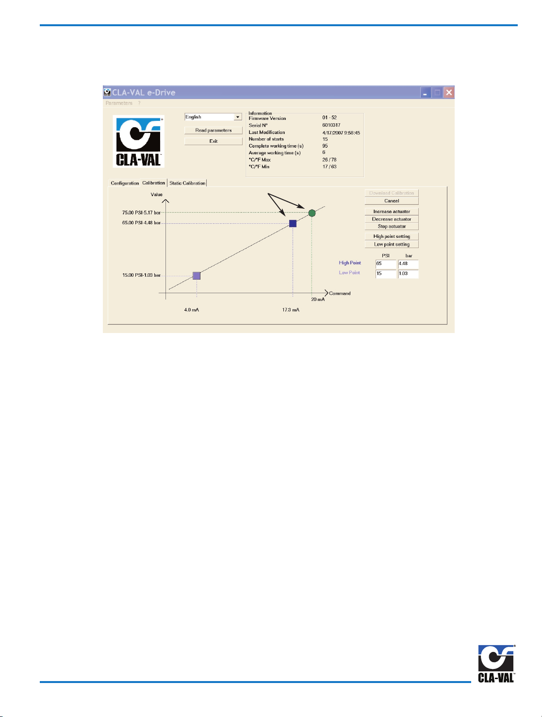
3) Click on Read parameters button to display Calibration tab window with system values and display of General Information.
The date of last calibration, the average and total working time since first power up, the number of starts, the serial
number, the Firmware version, and the maximum and minimum recorded temperature inside the actuator are displayed.
Also, Calibration tab window will open without clicking on Read parameters button.
4) Open Configuration tab window to change Rotation Speed. Change speed by adjusting actuator on and off times to equal
slower or faster net rotation speed. Factory default setting of one second on and five seconds off is a net rotation speed of
about one rpm. Longer off times will slow down the actuator. Maximum ratio of 1/1 is a net speed of six rpm. Click on
download to actuator button to make this parameter change without affecting other settings.
Slower rotation speeds are recommended.
5) Open Calibration tab mode to set (Loss-of-Signal mode). Select one of three options for actuator action upon
loss of 4 - 20 mA command input signal. If actuator has power it will do one of the following:
Go to 4 mA: Actuator will decrease pilot setting to 4 mA position.
Last position: Actuator will stay in last position. Highly recommended
Go to 20 mA: Actuator will increase pilot setting to 20 mA position.
Click on download to actuator button to make this parameter change.
In the event of loss of power, actuator will stay in last position and valve will control at last set-point.
Starting Actuator Software
32 Series Actuator and Software Set-up
Change 130VC-2 Actuator configuration from factory default settings,
by using free download software from website (www.cla-val.com). To
set up a communication link with 130VC-2 Actuator, first install
software and cable driver and then special USB communications
cable in laptop computer. After installing driver and communication
cable, the actuator must be powered for link to work. Follow hardware set-up and wiring diagram instructions. Your computer must
be on before powering the actuator.
Hardware set-up steps must be completed before program will
communicate and change 130VC-2 factory default settings. Until
wiring and power connections are made to the actuator, the software program can be opened, but new parameters can not be created or stored or sent to actuator. Changes to parameters must be
done "live" and while control valve is operating.
Install Special Communications CABLE
On 130VC-2 Actuator, remove small protective plastic cover and
attach Special Communications Cable to connector using short
orange wire and attach other cable end to computer USB port.
When finished running software and downloading settings to actuator, remove cable and reinstall small protective plastic cover.
Troubleshooting Actuator Software Set-up
Problem Check
The software is not opening
Are you using Windows XP or
Windows 2000?
No connection to actuator Check if the USB driver is working
Page 3
Fig. 1
Page 22

1) In Calibration Tab mode, click “Calibration Mode” button. This will allow temporary manual control of actuator for setting new
pilot control limits. These values will then be sent to actuator at completion of calibration. Check that actuator LED is
blinking red/green during calibration mode process. All High and Low point settings steps must be completed in order
shown. Use the cancel button to input new values.
2) Look at pressure gauge or flow sensor, use Increase actuator or Decrease actuator buttons until desired LOW pressure or
flow point (same value used in Configuration tab window and showing in Low Point window) is reached. Press Stop
actuator button to stop actuator. Use good quality gauges and be as precise as possible. If calibrating CDHS-32 for flow
rate using an orifice plate, a calibrated differential pressure gauge or transmitter is recommended.
3) Once desired low pressure or flow is reached and actuator is topped, click Low point setting button.
4) Look at pressure gauge or flow sensor, use Increase actuator or Decrease actuator buttons until desired HIGH pressure or
flow point (same value used in Configuration tab window and showing in High Point window) is reached. Press Stop
actuator button to stop actuator.
5) Once the high pressure or flow is reached and actuator is stopped, click High point setting button.
6) Finally, click Download calibration button to store values in actuator. High point, Low point, Loss-of-Signal, and Rotation
speed settings are sent to actuator. Actuator LED will change to green when complete. Unplug cable from actuator and
replace protective cap. 130VC-2 Actuator is now ready to accept 4 - 20 mA command signal from permanent cable Yellow
and Black wires.
Calibration - Actuator Limits Settings
Fig. 2
Page 4
Page 23
In some instances it may not be physically possible to reach desired system High pressure point due to possibility of putting
too much pressure in a zone. Projection calibration mode is an ideal solution for this situation.
1) Look at pressure gauge or flow sensor, use Increase actuator or Decrease actuator until HIGH pressure point is reached.
Press the Stop actuator button. Use good quality gauges and be as precise as possible. If calibrating CDHS-32 for flow
rate using an orifice plate, a calibrated differential pressure gauge or transmitter is recommended. Once low pressure or
flow is reached, click on Low point setting button.
2) Look at pressure gauge or flow sensor and use Increase actuator or Decrease actuator buttons to increase pressure or
flow as close as is practical to desired HIGH pressure point.
3) Enter this value in projected High point calibration window.
4) Next, click on the High point setting button, and then click on the Download calibration button. The actuator automatically
projects range to desired high point value entered in Configuration tab window.
5) New projected High point, Low point, Loss-of-Signal, and Rotation speed settings are sent to actuator. Actuator LED will
change to green when complete. Unplug cable from actuator and replace protection cap, actuator is now ready to accept
4 - 20 mA command signal from permanent cable Yellow and Black wires.
Calibration - Projection to New HIGH Value Point
Fig. 3
Page 5
Projected High Calibration
Page 24

In some applications it may not be physically possible to reach the low pressure point due to not being able to lower pressure
in a zone. Projection calibration mode is an ideal solution for this situation.
1) Look at pressure gauge or flow sensor and use Increase actuator or Decrease actuator until LOW pressure point is
reached. Press the Stop actuator button. Use good quality gauges and be as precise as possible. If calibrating CDHS-32
for flow rate using an orifice plate, a calibrated differential pressure gauge or transmitter is recommended. Once high
pressure or flow is reached and actuator stopped, click on high point setting button.
2) Look at the pressure gauge or flow sensor and use Increase actuator or Decrease actuator buttons to decrease pressure
or flow as close as practical to desired LOW pressure point.
3) Enter this value in the projected Low point calibration window.
4) Next click on Low point setting button, and then click on Download calibration button. The actuator automatically projects
range to desired low point value entered in Configuration tab window.
5) New projected Low point, High point, Loss-of-Signal, and Rotation speed settings are sent to actuator. Actuator LED will
change to green when complete. Unplug cable from actuator and replace protection cap, actuator is now ready to accept
4 - 20 mA command signal from permanent cable Yellow and Black wires.
If it is not practical to reach both high and low system value settings, then both projection procedures can be used. Allow
at least one fourth of total range between high and low starting points. Accuracy of projected values is based on
accuracy of initial value and any error will be magnified when projected from starting point.
Calibration - Projection to New LOW Value Point
Fig. 4
Page 6
Projected Low Calibration
Page 25

Static calibration can create low and high pressure points for the 4 and 20 milliamp signals without rotating the actuator.
1) Determine high and low pressure that corresponds to the 4-20 mA signals.
2) Open the "Static Calibration" mode.
3) Use existing system pressure as a reference point or change using the increase.
4) Once desired reference setting is attained, consult spring chart to obtain pressure change per pilot revolution.
5) Calculate the number of turns between the reference pressure and the low and high values.
6) Enter these numbers into the "Turn to low and to high points". Numbers must be positive and can contain up to
decimal points.
7) Click "Download Calibration" button to complete actuator setup.
8) Click cancel button to restart calibration.
Example: Required pressure range for 4-20 mA signals is 55 to 95 psi and system pressure is 70 psi. The 20-105 CRD-32 is
13 psi per turn. Therefore, 95 minus 55 divided by 13 = 1.92 turns is entered into the high point window. For the
low point settings: 70 minus 55 = 1.15 turns which is entered into the low point window.
(Remember to click "Download Calibration" button).
Spring Chart - PSI change per complete pilot revolution
CRD 15 -75 = 10.2 psi per turn
CRD 2-105 = 13 psi per turn
CRD 30-300 = 29 psi per turn
Static Calibration
Fig. 5
Page 7
Page 26

Troubleshooting FAQ
What are the default settings for the 130VC-2 actuator?
Factory default setting for 130VC-2 Actuator range parameter is the full pilot spring range scaled to match the 4 to 20 mA
Remote Command Input analog signal. Factory default setting for 130VC-2 Actuator rotation speed is one rpm with 24
VDC power.
How do I get the software to work with the actuator?
To set up a link with 130VC-2 Actuator, first install cable driver and then the special USB communications cable. After
installing driver and communication cable, the Actuator must be powered for link to work. Follow wiring diagram and hardware hookup instructions. Download Wiring Diagram from website (www.cla-val.com).
How do I install Special USB Communication Cable?
When 130VC-2 communications cable is installed in your laptop computer USB port for the first time, Windows will search
your computer for the cable USB driver. If Windows Plug and Play does not automatically find the driver and connect to
actuator, then the cable driver must be set up manually. Windows will take you step-by-step through the manual set up
process. The cable USB driver is installed during software download. You will have to browse to the Cla-Val folder created during download where the driver file is located. Details are in this manual.
My computer does not have a USB port
Older laptop computers with only Serial port may have a problem using USB to Serial adapter with special USB connector
cable and communicating with 130VC-2 actuator. Make sure the USB to Serial adapter cable is less than 18 inches long.
Also, USB extension cables should not be used because they will degrade signals and cause problems. If problem persists, consult Cla-Val factory technical support.
Can I set both high and low setting points by projection?
Both projection procedures can be used if it is not practical to reach high and low settings. Allow at least one fourth of total
range between high and low starting points. Accuracy of projected values is based on accuracy of initial value and any
error will be magnified when projected from starting point.
Why is actuator LED still blinking red/green after I downloaded the settings?
Once the calibration mode button is activated, all steps must be done before downloading is begun. Actuator LED will show
green when downloading is successful and complete.
Can I make a file ahead of time and download it to 130VC-2 later?
All hardware hookup steps must be completed before program will communicate and change 130VC-2 parameters. Until
wiring and power connections are made to the actuator, this program can be opened, but new parameters can not be created or stored or sent to the actuator. Changes to parameters must be done "live" and while control valve is operating.
Actuator LED will show green when downloading is successful and complete.
Can I make a file ahead of time and download it to 130VC-2 later?
All hardware hookup steps must be completed before program will communicate and change 130VC-2 parameters. Until
wiring and power connections are made to the actuator, this program can be opened, but new parameters can not be created or stored or sent to the actuator. Changes to parameters must be done "live" and while control valve is operating.
CLA-VAL EUROPE
Chemin des Mésanges 1
CH-1032 Romanel/
Lausanne, Switzerland
Phone: 41-21-643-15-55
Fax: 41-21-643-15-50
E-mail: cla-val@cla-val.ch
CLA-VAL FRANCE
Porte du Grand Lyon 1
ZAC du Champ du Périer
France - 01700 Neyron
Phone: 33-4-72-25-92-93
Fax: 33-4-72-25-04-17
E-mail: cla-val@cla-val.fr
CLA-VAL
PO Box 1325 Newport Beach CA 92659-0325
800-942-6326 Fax: 949-548-5441 Web Site: cla-val.com E-mail: claval@cla-val.com
©COPYRIGHT CLA-VAL 2007 Printed in USA S
p
ecifications subject to change without notice.
CLA-VAL CANADA
4687 Christie Drive
Beamsville, Ontario
Canada LOR 1B4
Phone: 905-563-4963
Fax: 905-563-4040
E-mail sales@cla-val.ca
CLA-VAL UK
Dainton House, Goods Station Road
GB - Tunbridge Wells
Kent TN1 2 DH England
Phone: 44-1892-514-400
Fax: 44-1892-543-423
E-mail: info@cla-val.co.uk
N-130VC-2 (R-7-07)
Appendix A
Page 27

Page 28

Page 29

Page 30
DESCRIPTION
The CRL Pressure Relief Control is a direct acting, spring loaded,
diaphragm type relief valve. It may be used as a self-contained valve or
as a pilot control for a Cla-Val Main valve. It opens and closes within
very close pressure limits.
INSTALLATION
The CRL Pressure Relief Control may be installed in any position. The
control body (7) has one inlet and one outlet port with a side pipe plug
(24) at each port. These plugs are used for control connections or gauge
applications. The inlet in the power unit body (6) is the sensing line port.
A flow arrow is marked on the body casting.
OPERATION
The CRL Pressure Relief Control is normally held closed by the force of
the compression spring above the diaphragm; control pressure is applied
under the diaphragm.
When the controlling pressure exceeds the spring setting, the disc is lifted
off its seat, permitting flow through the control.
When controlling pressure drops below spring setting, the spring returns
the control to its normally closed position.
ADJUSTMENT PROCEDURE
The CRL Pressure Relief Control can be adjusted to provide a relief setting at any point within the range found on the nameplate.
Pressure adjustment is made by turning the adjustment screw (9) to vary
the spring pressure on the diaphragm. Turning the adjustment screw
clockwise increases the pressure required to open the valve.
Counterclockwise decreases the pressure required to open the valve.
When pressure adjustments are complete the jam nut (10) should be
tightened and the protective cap (1) replaced. If there is a problem of
tampering, lock wire holes have been provided in cap and cover. Wire
the cap to cover and secure with lead seal.
DISASSEMBLY
The CRL Pressure Relief Control does not need to be removed from the
line for disassembly. Make sure that pressure shut down is accompanied
prior to disassembly. If the CRL is removed from the line for disassembly
be sure to use a soft jawed vise to hold body during work.
Refer to Parts List Drawing for Item Numbers.
1. Remove cap (1), loosen jam nut (10) and turn adjusting
screw counterclockwise until spring tension is relieved.
2. Remove the eight screws (4) holding the cover (3) and
powerunit body (6). Hold the cover and powerunit together
and place on a suitable work surface.
See NOTE under REASSEMBLY.
3. Remove the cover (3) from powerunit body (6). The spring
(12) and two spring guides (11).
4. Remove nut (13) from stem (19) and slide off the belleville washer
(14), the upper diaphragm washer (15) and the diaphragm (16).
5. Pull the stem (19) with the disc retainer assembly (21) through the
bottom of powerunit. The lower diaphragm washer (17) will slide off
of stem top.
6. Remove jam nut (23) and disc retainer assembly (21) from stem.
Use soft jawed pliers or vise to hold stem. The polished surface of
stem must not be scored or scratched.
7. The seat (22) need not be removed unless it is damaged. If removal
is necessary use proper size socket wrench and turn counterclock
wise.
Note: Some models have an integral seat in the body (7).
INSPECTION
Inspect all parts for damage, or evidence of cross threading. Check
diaphragm and disc retainer assembly for tears, abrasions or other damage. Check all metal parts for damage, corrosion or excessive wear.
REPAIR AND REPLACEMENT
Minor nicks and scratches may be polished out using 400 grit wet or dry
sandpaper fine emery or crocus cloth. Replace all O-rings and any damaged parts.
When ordering replacement parts, be sure to specify parts list item number and all nameplate data.
REASSEMBLY
In general, reassembly is the reverse of disassembly. However, the following steps should be observed:
1. Lubricate the O-Ring (18) with a small amount of a good grade of
waterproof grease, (Dow Corning 44 medium grade or equal).
Use grease sparingly and install O-ring in powerunit body (6).
2. Install stem (19) in powerunit body (6). Use a rotating motion with
minimum pressure to let stem pass through O-ring.
Do Not Cut O-Ring.
3. Install O-ring (5) at top of stem (19). Place lower diaphragm
washer (17) on the stem with the serrated side up. Position
diaphragm (16), upper diaphragm washer (15), with serration down,
and belleville washer (14) with concave side down.
4. Position powerunit body (6) as shown on parts list drawing (top view).
5. Continue reassembly as outlined in disassembly steps 1 through 3.
Pressure Relief Control
CRL
Note: Item (4) Screw will have a quantity of 8 for the 0-75 and 20-200psi
design and a quantity of 4 for the 100-300psi design. Item (25) Screw is
used on the 100-300psi design only. Install item (25), before item (4) for
preload of item (12) spring.
SYMPTOM PROBABLE CAUSE REMEDY
Fails to open. Controlling pressure
too low.
Back off adjusting
screw until valve
opens.
Fails to open with
spring compression
removed.
Mechanical obstruction, corrosion, scale
build-up on stem.
Disassemble,
locate,and remove
obstruction, scale.
Leakage from cover
vent hole when controlling pressure is
applied.
Diaphragm Damage Disassembly replace
damaged
diaphragm.
Fails to close with
spring compressed.
Mechanical obstruction.
Disassemble, locate
and remove
obstruction.
Fails to close. No spring compres-
sion.
Re-set pressure
adjustment.
Loose diaphragm
assembly.
Tighten upper
diaphragm washer.
MODEL
INSTALLATION / OPERATION / MAINTENANCE
CLA-VAL
Copyright Cla-Val 2011 Printed in USA Specifications subject to change without notice.
P.O. Box 1325 • Newport Beach, CA 92659-0325 • Phone: 949-722-4800 • Fax: 949-548-5441 • E-mail: claval@cla-val.com • Website cla-val.com
©
N-CRL (R-3/2011)
Page 31

1/2" & 3/4" PRESSURE RELIEF CONTROL
(Bronze Body with 303SS Trim)
CRL
Ajusting Screw
(3/8" - 16UNF THREAD)
9
1
10
3
11
12
14
13
11
8
22
23
7
18
19
21
INLET
1/8 - 27 NPT
SENSING
CONNECTION
(TYP.)
7.44
MAX
.71
OUTLET
20
6
2
0 TO 75 AND
20 TO 200 PSI
DESIGN
5
17
16
15
4
1
9
10
3
11
12
18
7
2
100 To 300 psi Design
.71
ADJUSTING SCREW
(1/2" 20UNF THREAD)
10.44
MAX.
When ordering parts please specify:
1. All Nameplate Data
2. Item Part Number
3. Item Description
24
4
45º
3.12
DIA.
TRUE LOCATION OF
SENSING
CONNECTION
(TYP.)
Body with
integral Seat
CLA-VAL
Copyright Cla-Val 2011 Printed in USA Specifications subject to change without notice.
P.O. Box 1325 • Newport Beach, CA 92659-0325 • Phone: 949-722-4800 • Fax: 949-548-5441 • E-mail: claval@cla-val.com • Website cla-val.com
©
PL-CRL (R-8/2011)
PARTS LIST
Item Description Material Part Number Part Number Part Number Part Number
0-75 20-105 20-200 100-300
1 Cap Plastic 67628J 67628J 67628J 1257601D
2 Nameplate Brass -- -- -- -3 Cover Bronze C2544K C2544K C2544K 44587E
4* Screw Fil. Hd. 10-32 x 1.88 (Qty 8) 303 SS 6757867E 6757867E 6757867E 6757867E
5* O-Ring Rubber 00902H 00902H 00902H 00902H
6 Body, Powerunit Bronze 7920504D 7920504D 7920504D 7920504D
7 1/2” Body Bronze C7928K C7928K C7928K C7928K
3/4” Body Bronze C9083B C9083B C9083B C9083B
8* O-Ring, Seat Rubber 00718H 00718H 00718H 00718H
9 Screw, Adjusting Brass 7188201D 7188201D 7188201D 82811B
10 Nut Hex (Locking) 303 SS 6780106J 6780106J 6780106J 6780606H
11 Guide, Spring 303 SS 71881H 71881H 71881H 1630301J
12 Spring CHR/VAN 71884B 20632101E 71885J 1630201A
13 Nut, Stem Upper Bronze 73034B 73034B 73034B 73034B
14 Washer, Belleville Steel 7055007E 7055007E 7055007E 7055007E
15 Washer, Diaphragm (upper) 303 SS 71891G 71891G 71891G 71891G
16* Diaphragm Rubber C1505B C1505B C1505B C1505B
17 Washer, Diaphragm (lower) 303 SS 45871B 45871B 45871B 45871B
18* O-Ring, Stem Rubber 00746J 00746J 00746J 00746J
19 Stem 303 SS 8982401F 8982401F 8982401F 8982401F
20* O-Ring, Body Rubber 00767E 00767E 00767E 00767E
21* Retainer Assembly, Disc 303 SS C9158B C9158B C9158B C9158B
22 Seat 303Rub 62187A 62187A 62187A 62187A
23 Nut, Hex, Stem, Lower Bronze 6779806G 6779806G 6779806G 6779806G
24 Pipe Plug Bronze 6784701C 6784701C 6784701C 6784701C
FACTORY SET POINT 50 PSI 60 PSI 60 PSI 100 PSI
REPAIR KIT* 9170007A 9170007A 9170007A 9170007A
CRL
Range PSI
APPROX. INCREASE
FOR EACH
CLOCKWISE TURN OF
ADJUSTING SCREW
0 to 75 8.5 PSI
20 to 105 12.5 PSI
20 to 200 28.0 PSI
100 to 300 18.0 PSI
SIZE SPRING
PART
NUMBER
1/2” 0-75 PSI 7922201E
1/2” 20-105 PSI 7922205F
1/2” 20-200 PSI 7922202C
1/2” 100-300 PSI 8280901D
3/4” 0-75 PSI 7922901K
3/4” 20-105 PSI 7922903F
3/4” 20-200 PSI 7922902H
3/4” 100-300 PSI 8600501E
For 250-600 PSI Contact Factory
Page 32

*This drawing is the property of CLA-VAL and same and copies made thereof, if any, shall be returned to it upon demand. Delivery and disclosure hereof are made solely
upon condition that the same shall not be used, copied ore reproduced, nor shall the subject here of be disclosed in any manner to anyone for any purpose, except as
herein authorized, without prior approval of CLA-VAL. Whether or not the equipment or information shown hereon is patented or otherwise protected, full title and copyrights if any, in and to this drawing and/or information delivered or submitted are fully reserved by CLA-VAL.
Dwg#47117
Regulator Spring Color Coding Chart
THE FOLLOWING CONTROL & SPRING P/N#'S WERE REMOVED, 32656B, 31554K, 44591G, V65695B, & V5695B.
ADDED CRL-13, CRL-5A, CRA, CRA-10A, CHANGED SPRING RANGES TO MATCH CURRENT CONTROLS.
CLA-VAL
Copyright Cla-Val 2010 Printed in USA Specifications subject to change without notice.
P.O. Box 1325 • Newport Beach, CA 92659-0325 • Phone: 949-722-4800 • Fax: 949-548-5441 • E-mail: claval@cla-val.com • Website cla-val.com
©
PL-47117 AF (R-4/2010)
PARTS LIST
WIRE SIZE SPRING NUMBER COLOR WIRE MATERIAL CATALOG NUMBER PSI RANGE *PSI PER TURN
.080 DIA. C0492D BLUE S.S.
CDB-7
CRL-5A
0-7
0-7
.75
.75
.018 DIA. 82575C -- S.S.
CRD
CRD-10A
1.9-6.5
1.9-6.5
.61
.49
.116 DIA. 81594E -- S.S.
CRD
CRD-10A
2-30
2-30
3.0
2.4
.120 DIA. V5654J GREEN CHR VAN
CRL-5A
CRD
5-25
10-40
4.0
4.0
.162 DIA. 32447F NATURAL S.S.
CDB-7
CRL-5A
CRL-13
10-60
10-60
10-60
12.0
12.0
12.0
.162 DIA. V5695B YELLOW MUSIC WIRE
CDB-7
CRL-5A
CRL-13
20-80
20-80
20-80
14.5
14.5
14.5
.207 DIA. C1124B CAD PLT MUSIC WIRE
CDB-7
CRL-13
CRL-5A
50-150
50-150
50-150
29.5
29.5
29.5
.225 DIA. V6515A RED MUSIC WIRE
CDB-7
CRL-13
CRL-5A
65-180
65-180
65-180
44.0
44.0
44.0
.115 X .218 71884B RED CHR VAN
CRL
CRD
CRD-10A
0-75
15-75
15-75
8.5
9.0
7.2
.118 X .225 71885J GREEN CHR VAN
CRL
CRD
CRD-10A
20-200
30-300
30-300
28.0
27.0
22.4
.225 X .295 1630201A CAD PLT CHR VAN
CRL
CRL-5A
100-300
100-300
18.00
18.00
.440 X .219 48211H CAD PLT STEEL
CRA-18
CRD-22
CRL-4A
200-450
200-450
100-450
17.0
17.0
17.0
.187 20632101E BLACK 316 SST
CRD
CRL
20-105
20-105
13.0
13.0
WIRE SIZE SPRING NUMBER COLOR WIRE MATERIAL CATALOG NUMBER FEET RANGE *FEET PER TURN
.080 DIA. C0492D BLUE S.S.
CRA
CRD-2
4.5-15
4.5-15
.82
.82
.375 DIA.
87719B
1 SPRING
2 SPRING
3 SPRING
4 SPRING
5 SPRING
EPOXY
COATED
CHROME SILICON CDS-5
5-40
30-80
70-120
110-120
150-200
1.0
2.0
3.0
4.0
5.0
.072 DIA. V5097A -- 302SS CVC 1-17 .7
.375 DIA.
2933502H
1 SPRING
2 SPRING
3 SPRING
4 SPRING
5 SPRING
EPOXY
COATED
CHROME SILICON CDS-6A
5-40
30-80
70-120
110-160
150-200
.75
1.50
2.20
3.00
3.70
*THESE FIGURES ARE ONLY APPROXIMATE. FINAL ADJUSTMENTS SHOULD BE MADE WITH A PRESSURE GAGE.
Page 33
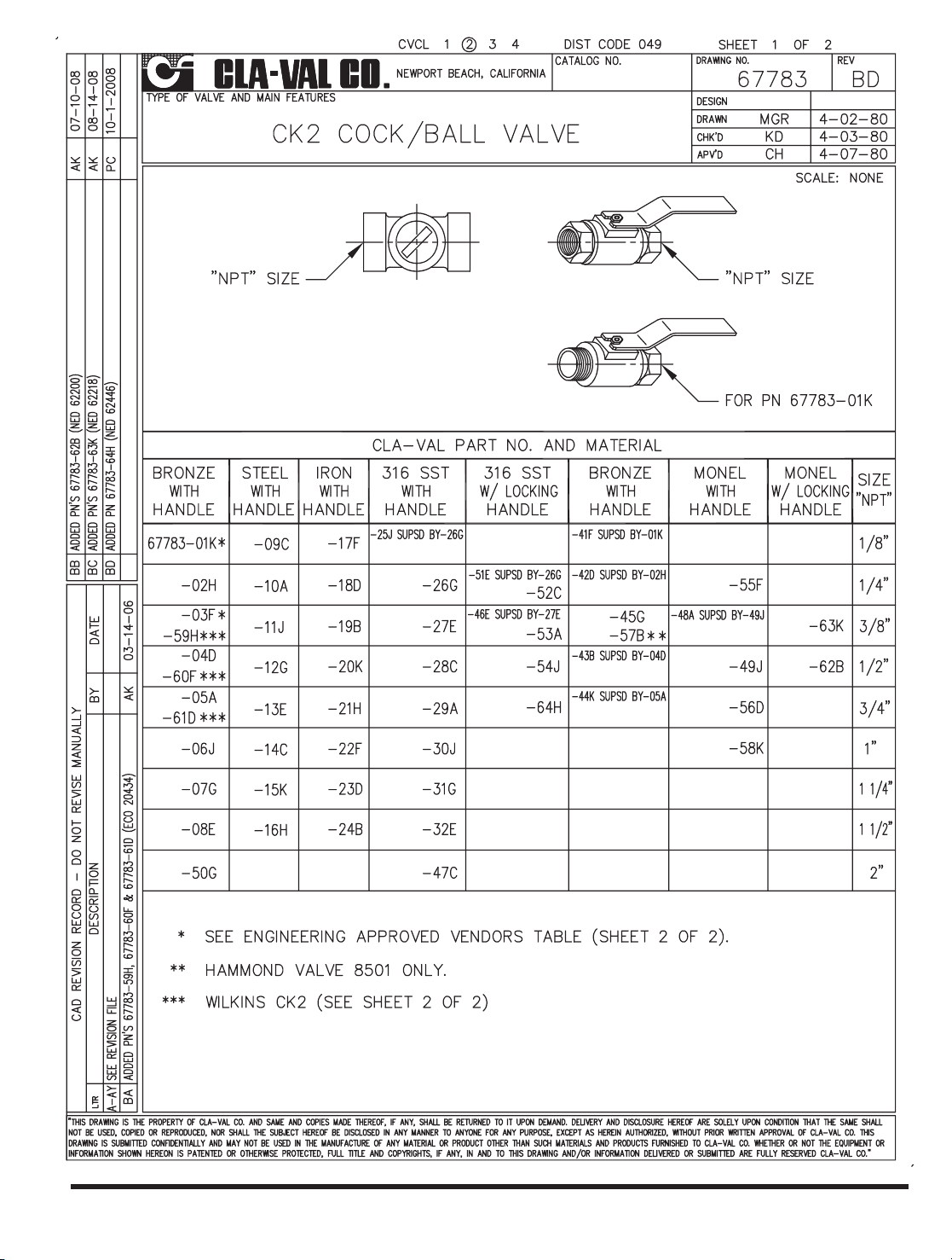
CLA-VAL
Copyright Cla-Val 2011 Printed in USA Specifications subject to change without notice.
P.O. Box 1325 • Newport Beach, CA 92659-0325 • Phone: 949-722-4800 • Fax: 949-548-5441 • E-mail: claval@cla-val.com • Website cla-val.com
©
PL-CK2 (R-3/2011)
Page 34

The strainer is designed for use in conjunction with a Cla-Val
Main Valve, but can be installed in any piping system where
there is a moving fluid stream to keep it clean. When it is used
with the Cla-Val Valve, it is threaded into the upstream body port
provided for it on the side of the valve. It projects through the
side of the Main Valve into the flow stream. All liquid shunted to
the pilot control system and to the cover chamber of the Main
Valve passes through the X46 Flow Clean Strainer.
C
Male
Pipe
SAE
H
D
E
B
I
G
Male
Pipe
B
I
Width Across Flats
Female
Pipe
A
D
E
F
• Self Scrubbing Cleaning Action
• Straight Type or Angle Type
The Cla-Val Model X46 Strainer is designed to prevent passage of
foreign particles larger than .015". It is especially effective against
such contaminant as algae, mud, scale, wood pulp, moss, and root
fibers. There is a model for every Cla-Val. valve.
The X46 Flow Clean strainer operates on a velocity principle utilizing
the circular "air foil" section to make it self cleaning. Impingement of
particles is on the "leading edge" only. The low pressure area on the
downstream side of the screen prevents foreign particles from clogging the screen. There is also a scouring action, due to eddy currents, which keeps most of the screen area clean.
Dimensions
(In Inches)
INSTALLATION
X46 Angle Type B (In Inches)
B
(NPT)C(SAE)
DEH I
1/8 1/4 1-3/8 5/8 7/8 1/4
1/4 1/4 1-3/4 3/4 1 3/8
3/8 1/4 2 7/8 1 1/2
3/8 3/8 1-7/8 7/8 1 1/2
1/2 3/8 2-3/8 1 1-1/4 5/8
X46A Straight
X46B Angle
X46A Straight Type A (In Inches)
A B D E F G I
1/8 1/8 1-3/4 3/4 1/2 1/2 1/4
1/4 1/4 2-1/4 1 3/4 3/4 3/8
3/8 3/8 2-1/2 1 7/8 7/8 1/2
3/8 1/2 2-1/2 1-1/4 1/2 7/8 3/4
1/2 1/2 3 1-1/4 1 1-1/8 3/4
3/8 3/4 3-3/8 2 1/2 1 7/8
3/4 3/4 4 2 1 1-1/2 7/8
3/8 1 4-1/4 2-3/4 1/2 1-3/8 7/8
1 1 4-1/2 2-3/4 1-1/4 1-3/4 7/8
1/2 1 4-1/4 2-3/4 1/2 1-3/8 7/8
Flow Clean Strainer
X46
INSPECTION
Inspect internal and external threads for damage or evidence
of cross-threading. Check inner and outer screens for clogging,
embedded foreign particles, breaks, cracks, corrosion, fatigue,
and other signs of damage.
CLEANING
After inspection, cleaning of the X46 can begin. Water service usually will produce
mineral or lime deposits on metal parts in contact with water. These deposits can
be cleaned by dipping X46 in a 5-percent muriatic acid solution just long enough
for deposit to dissolve. This will remove most of the common types of deposits.
Caution: use extreme care when handling acid. If the deposit is not removed
by acid, then a fine grit (400) wet or dry sandpaper can be used with water.
Rinse parts in water before handling. An appropriate solvent can clean parts used
in fueling service. Dry with compressed air or a clean, lint-free cloth.
Protect from damage and dust until reassembled.
REPLACEMENT
If there is any sign of damage, or if there is the slightest doubt that the Model X46
Flow Clean Strainer may not afford completely satisfactory operation, replace it. Use
Inspection steps as a guide. Neither inner screen, outer screen, nor housing is furnished as a replacement part. Replace Model X46 Flow Clean Strainer as a complete unit.
When ordering replacement Flow-Clean Strainers, it is important to determine pipe
size of the tapped hole into which the strainer will be inserted (refer to column A or
F), and the size of the external connection (refer to column B or G).
When Ordering,
Please Specify:
• Catalog Number X46
• Straight Type or Angle Type
• Size Inserted Into and Size Connection
• Materials
DISASSEMBLY
Do not attempt to remove the screens from the strainer housing.
MODEL
INSTALLATION / OPERATION / MAINTENANCE
CLA-VAL
Copyright Cla-Val 2011 Printed in USA Specifications subject to change without notice.
P.O. Box 1325 • Newport Beach, CA 92659-0325 • Phone: 949-722-4800 • Fax: 949-548-5441 • E-mail: claval@cla-val.com • Website cla-val.com
©
N-X46 (R-3/2011)
(NPT) (NPT)
X46B
X46A
Page 35

CLA-VAL
Copyright Cla-Val 2011 Printed in USA Specifications subject to change without notice.
P.O. Box 1325 • Newport Beach, CA 92659-0325 • Phone: 949-722-4800 • Fax: 949-548-5441 • E-mail: claval@cla-val.com • Website cla-val.com
©
INSTALLATION / OPERATION / MAINTENANCE
Flow Control
CV
MODEL
N-CV (R-3/2011)
DESCRIPTION
The Cla-Val Model CV Flow Control is a simply-designed,
spring-loaded check valve. Rate of flow is full flow in one direction and restricted in other direction. Flow is adjustable in the
restricted direction. It is intended for use in conjunction with a
pilot control system on a Cla-Val Automatic Control Valve.
OPERATION
The CV Flow Control permits full flow from port A to B, and
restricted flow in the reverse direction. Flow from port A to B
lifts the disc from seat, permitting full flow. Flow in the reverse
direction seats the disc, causing fluid to pass through the clearance between the stem and the disc. This clearance can be
increased, thereby increasing the restricted flow, by screwing
the stem out, or counter-clockwise. Turning the stem in, or
clockwise reduces the clearance between the stem and the
disc, thereby reducing the restricted flow.’
INSTALLATION
Install the CV Flow Control as shown in the valve schematic All
connections must be tight to prevent leakage.
DISASSEMBLY
Follow the sequence of the item numbers assigned to the
parts in the cross sectional illustration for recommended
order of disassembly.
Use a scriber, or similar sharp-pointed tool to remove O-ring
from the stem.
INSPECTION
Inspect all threads for damage or evidence of cross- threading. Check mating surface of seat and valve disc for excessive scoring or embedded foreign particles. Check spring for
visible distortion, cracks and breaks. Inspect all parts for
damage, corrosion and cleanliness.
CLEANING
After disassembly and inspection, cleaning of the parts can
begin. Water service usually will produce mineral or lime
deposits on metal parts in contact with water. These
deposits can be cleaned by dipping the parts in a 5-percent
muriatic acid solution just long enough for deposits to dissolve. This will remove most of the common types of
deposits. Caution: use extreme care when handling acid.
If the deposit is not removed by acid, then a fine grit (400)
wet or dry sandpaper can be used with water. Rinse parts
in water before handling. An appropriate solvent can clean
parts used in fueling service. Dry with compressed air or a
clean, lint-free cloth. Protect from damage and dust until
reassembled.
REPAIR AND REPLACEMENT
Minor nicks and scratches may be polished out using a fine
grade of emery or crocus cloth; replace parts if scratches
cannot be removed.
Replace O-ring packing and gasket each time CV Flow
Control is overhauled.
Replace all parts which are defective. Replace any parts
which create the slightest doubt that they will not afford completely satisfactory operation. Use Inspection steps as a
guide.
REASSEMBLY
Reassembly is the reverse of disassembly; no special tools
are required.
TEST PROCEDURE
No testing of the flow Control is required prior to reassembly
to the pilot control system on Cla-Val Main Valve.
Page 36

3/8" Flow Control
CV
2.12
MAX
STAMP PART NO. ON
SMOOTH SURFACE
RESTRICTED
FLOW
3/8 - 18 NPT
1.84
ADJUSTING STEM
(TURN CLOCKWISE TO
INCREASE RESTRICTION)
1
7
2
10
9
8
6
5
4
3
.85
FREE FLOW
BAR STOCK
CONFIGURATION
When ordering parts,
please specify:
• Number Stamped on Side
• Description (CV Flow Control)
• Part Description
• Material
CLA-VAL
Copyright Cla-Val 2011 Printed in USA Specifications subject to change without notice.
P.O. Box 1325 • Newport Beach, CA 92659-0325 • Phone: 949-722-4800 • Fax: 949-548-5441 • E-mail: claval@cla-val.com • Website cla-val.com
©
PL-CV (R-3/2011)
PARTS LIST
ITEM DESCRIPTION QTY
1
Cap (SS only)
1
2
Nut, Jam
1
3
Seat
1
4
Gasket
1
5
Disc
1
6
Spring
1
7
Ring, Retaining
1
8
Stem
1
9
O-Ring
1
10
Housing
1
Page 37

CLA-VAL
Copyright Cla-Val 2011 Printed in USA Specifications subject to change without notice.
P.O. Box 1325 • Newport Beach, CA 92659-0325 • Phone: 949-722-4800 • Fax: 949-548-5441 • E-mail: claval@cla-val.com • Website cla-val.com
©
Dimensions
Available only in replacement assembly.
PL-CDC-1 (R-6/2011)
NPT
5
3
4
2
1
I
Full Open Operation
NPT
5
3
4
2
1
I
Tight Closing Operation
B
C
A
NSF 61
Approved
Item Description Material
1 Body Brass
2
End
Connection
Brass
3 Disc Polytherimide
4 Seat NBR
5 Spring Stainless Steel
Size
(NPT)
Stock
Number
A B C I CVpsi Wt.
3/8" 9834501A 1.73 0.79 1.06 0.40 4.55 400 0.37
1/2" 9834502J 2.32 0.98 1.35 0.53 6.00 400 0.32
• NSF 61 Approved
• Meets low lead requirements
• Soft Seat for Bubble Tight Shutoff, Spring Loaded for
Fast Seating Action
• Compact Design
• Low Cracking Pressure 1/2 psi
• Flow Profile Designed to Minimize Head Loss
• Perfect Seating both at High and Low Pressure, Wide
Temperature Range: +10
° to 210°F
•
Polyethermide Disc to ensure the Best Resistance for
Corrosion and Abrasion
•
Patented Disc Guide to Prevent Any Side Loading
CDC-1
PARTS LIST
Check Valve (Sizes 3/8” and 1/2”)
MODEL
Page 38

1
2
3
4
5
3/8 NPT
2.06
2.72
Strainer
X43
Standard 60 mesh pilot system strainer for fluid service.
CLA-VAL
Copyright Cla-Val 2011 Printed in USA Specifications subject to change without notice.
P.O. Box 1325 • Newport Beach, CA 92659-0325 • Phone: 949-722-4800 • Fax: 949-548-5441 • E-mail: claval@cla-val.com • Website cla-val.com
©
PL- X43 (R-3/2011)
PARTS LIST
ITEM DESCRIPTION MATERIAL
1
Pipe Plug Steel
2
Strainer Plug Brass
3
Gasket Copper
4
Screen SST
5
Body Brass
No parts available. Rreplacement assembly only.
Size Stock Number
3/8 x 3/8 33450J
Page 39
Complete Replacement Diaphragm Assemblies for 100-01 and 100-20 Hytrol Main Valves
For:
Hytrol Main Valves with Ductile Iron, Bronze Trim Materials—125/150 Pressure Class Only.
FACTORY ASSEMBLED
Includes: Stem, Disc Guide, Disc, Disc Retainer, Spacer Washers, Diaphragm, Diaphragm Washer
and Stem Nut.
3/8"
1/2" - 3/4"
1"
1 1/4"-1 1/2"
2"
2 1/2"
3"
4"
(Also 81-01 )
(Also 81-01 )
N/A
N/A
N/A
N/A
N/A
N/A
C2524B
C2525J
6"
8"
10"
12"
14"
16"
20"
24"
40456G
45276D
81752J
85533J
89067D
89068B
N/A
N/A
33273E
40456G
45276D
81752J
N/A
85533J
89068B
89068B
Valve
Size
Valve
Size
49097K
C2518D
C2520K
C2522 F
C2524B
C2523D
C2525J
33273E
100-01 100-20
Diaphragm Assembly
Stock Number
100-01 100-20
Diaphragm Assembly
Stock Number
3/8"
1/2" - 3/4"
1"
1 1/4" - 1 1/2"
2"
2 1/2"
3"
4"
6"
8"
10"
12"
14"
16"
20"
24"
(Also 81-01 )
(Also 81-01 )
N/A
N/A
N/A
N/A
N/A
N/A
9169805A
9169812G
9169813E
9169815K
9817901D
9817902B
N/A
9817903K
9817905E
9817905E
3/8"
1/2" - 3/4"
1"
1 1/4” - 1 1/2"
2"
2 1/2"
3"
4"
6"
8"
9169806J
9169807G
9169808E
9169809C
9169810A
9169817F
9169818D
9169819B
9169820K
9169834A
N/A
N/A
N/A
N/A
N/A
N/A
9169810A
9169818D
9169819B
9169820K
Valve
Size
Valve
Size
9169801K
9169802H
9169803F
9169804D
9169805A
9169811J
9169812G
9169813E
9169815K
9817901D
9817902B
9817903K
9817904H
9817905E
N/A
9817906C
100-01 100-20
Repair Kit
Stock Number
100-01 100-20
Repair Kit
Stock Number
Repair Kits for 100-01/100-20 Hytrol Valves
For:
Hytrol Main Valves—125/150 Pressure Class Only.
Includes: Diaphragm, Disc (or Disc Assembly) and spare Spacer Washers.
(Also 81-01 )
(Also 81-01 )
REPAIR KITS
When ordering, please give complete nameplate data of the valve and/or control being repaired.
MINIMUM ORDER CHARGE APPLIES.
Buna-N®Standard Material
Viton (For KB Valves)
MODEL
INSTALLATION / OPERATION / MAINTENANCE
Page 40

Repair Kits for 100-04/100-23 Hy-Check Main Valves
For:
Hy-Check Main Valves—125/150 Pressure Class Only
Includes: Diaphragm, Disc and O-Rings and full set of spare Spacer Washers.
Larger Sizes: Consult Factory.
Repair Kits for 100-02/100-21 Powertrol and 100-03/100-22 Powercheck Main Valves
For:
Powertrol and Powercheck Main Valves—125/150 Pressure Class Only
Includes: Diaphragm, Disc (or Disc Assembly) and O-rings and full set of spare Spacer Washers.
Repair Kits for Pilot Control Valves (In Standard Materials Only)
Includes: Diaphragm, Disc (or Disc Assembly), O-Rings, Gaskets or spare Screws as appropriate.
Repair Assemblies (In Standard Materials Only)
CLA-VAL
Copyright Cla-Val 2011 Printed in USA Specifications subject to change without notice.
P.O. Box 1325 • Newport Beach, CA 92659-0325 • Phone: 949-722-4800 • Fax: 949-548-5441 • E-mail: claval@cla-val.com • Website cla-val.com
©
N-RK (R-3/2011)
Valve
Size
Kit Stock Number
100-02
Valve
Size
Kit Stock Number
100-02 & 100-03 100-21 & 100-22
3
⁄8”
9169901H
2
1
⁄2”
9169910J N/A
1
⁄2” &3⁄4”
9169902F
3”
9169911G 9169905J
1” 9169903D
4”
9169912E 9169911G
1
1
⁄4” &11⁄2”
9169904B
6”
9169913C 9169912E
2” 9169905J
8”
99116G 9169913C
10”
9169939H 99116G
12"
9169937B 9169939H
Valve
Size
Kit Stock Number
Valve
Size
Kit Stock Number
100-04 100-23 100-04 100-23
4” 20210901B N/A 12” 20210905H 20210904J
6” 20210902A 20210901B 14” 20210906G N/A
8” 20210903K 20210902A 16” 20210907F 20210905H
10” 20210904J 20210903K 20” N/A 20210907F
24” N/A 20210907F
BUNA-N
®
(Standard Material)
VITON (For KB Controls)
Pilot
Control
Kit
Stock
Number
Pilot
Control
Kit
Stock
Number
Pilot
Control
Kit
Stock
Number
CDB 9170006C CFM-7 1263901K CDB-KB 9170012A
CDB-30 9170023H CFM-7A 1263901K CRA-KB N/A
CDB-31 9170024F CFM-9 12223E
CRD-KB (w/bucking spring)
9170008J
CDB-7 9170017K
CRA (w/bucking spring)
9170001D CRL-KB 9170013J
CDH-2 18225D
CRD (w/bucking spring)
9170002B CDHS-2BKB 9170010E
CDHS-2 44607A
CRD (no bucking spring)
9170003K CDHS-2FKB 9170011C
CDHS-2B 9170004H CRD-18 20275401K CDHS-18KB (no bucking spring) 9170009G
CDHS-2F 9170005E CRD-22 98923G
102C-KB
1726202D
CDHS-3C-A2 24657K CRL (55F, 55L) 9170007A
CDHS-8A 2666901A CRL-4A 43413E
CDHS-18 9170003K CRL-5 (55B) 65755B
CDS-4 9170014G CRL-5A (55G) 20666E
CDS-5 14200A CRL-18 20309801C
CDS-6 20119301A CV 9170019F
Buna-N
®
CDS-6A 20349401C X105L (O-ring) 00951E
CFCM-M1 1222301C 102B-1 1502201F CRD Disc Ret. (Solid) C5256H
CFM-2 12223E 102C-2 1726201F CRD Disc Ret. (Spring) C5255K
102C-3 1726201F
Control Description Stock Number
CF1-C1 Pilot Assembly Only 89541H
CF1-Cl Complete Float Control less Ball and Rod 89016A
CFC2-C1 Disc, Distributor and Seals 2674701E
CSM 11-A2-2 Mechanical Parts Assembly 97544B
CSM 11-A2-2 Pilot Assembly Only 18053K
33A 1" Complete Internal Assembly and Seal 2036030B
33A 2" Complete Internal Assembly and Seal 2040830J
When ordering, please give complete nameplate data of the valve and/or control being repaired. MINIMUM ORDER CHARGE APPLIES
Larger Sizes: Consult Factory.
 Loading...