

Page 1

131-73/631-73
Page 2

Page 3

Page 4

Page 5

Principle of Operation
Powertrol Valve
100-02
DESCRIPTION
This manual contains information for installation, operation and maintenance of the Cla-Val Co. 100-02 Powertrol, an automatic valve
designed for use where independent operating pressure is desired,or
when line fluid is unsuitable as an operating medium.
This valve is a hydraulically operated, diaphragm type, globe or angle
pattern valve. it is single seated and incorporates into its design two
operating chambers sealed from one another by a flexible synthetic
rubber diaphragm. Pressure applied to the upper chamber closes the
valve; when applied to the lower chamber, it opens the valve.
With proper pilot controls, the valve can be held in any intermediate
position between fully open and tightly closed.
INSTALLATION
Allow sufficient room around the valve assembly to make adjustments
and for disassembly.
NOTE: BEFORE THE VALVE IS INSTALLED, PIPE LINES
SHOULD BE FLUSHED OF ALL CHIPS, SCALE AND FOREIGN
MATTER.
It is recommended that gate or block valves be installed on both the
upstream and downstream sides of the 100-02 to facilitate isolating
the valve for preventative maintenance.
Place the valve in the line with flow through the valve in the direction
indicated on the inlet name plate or by flow arrows.
Cla-Val Powertrol Valves operate with maximum efficiency when
mounted in horizontal piping with cover "UP,' however, other positions
are acceptable. Due to the size and weight of the cover and internal
assembly of 4" and larger valves, installation with the cover "UP" is
advisable. This makes periodic inspection of internal parts readily
accessible.
When a pilot control system is installed on the Powertrol Valve, use
care to prevent damage. If it is necessary to remove fittings or components, be sure they are kept clean and replaced in the exact order
of removal.
After the valve is installed and the system is first pressurized, vent air
from the cover chamber and tubing by loosening fit" sings at all high
points.
Full Open Operation
When operating pressure below the
diaphragm is applied and operating, pressure
is relieved from the cover chamber, the valve
is held open, allowing full flow.
Modulating Action
The valve holds any intermediate position
when operating pressure is equal above and
below the diaphragm. A Cla-Val four-way pilot
control with "lock" position can maintain this
balance by stopping flow in the pilot control
system.
Tight Closing Operation
When pressure below the diaphragm is
relieved and operating pressure is applied to
the cover chamber, the valve closes drip-tight.
4 - Way Control 4 - Way Control 4 - Way Control with lock
TROUBLE SHOOTING
The following trouble shooting information deals strictly with the
Powertrol Valve; however some 'impossible causes" will refer to components that may exist in the variety of control systems available for the
valve. All trouble shooting is possible without removing the valve from
the line.
CAUTION: Extreme care should be taken when servicing the valve.
Gate or line block valves must be closed upstream and downstream of
the valve before starting disassembly. When there are no block or gate
valves to isolate the Powertrol Valve it should be realized that the valve
cannot be serviced under pressure. Steps must be taken to remedy this
situation before proceeding.
1.
2.
3.
4.
5.
6.
MODEL
INSTALLATION / OPERATION / MAINTENANCE
(Full Internal Port)
Page 6

FREEDOM OF MOVEMENT
The following procedures can be used to determine if the
valve opens and closes fully. During this test the diaphragm
can be checked for damage.
1.The Powertrol Valve will have a control to open and close
the valve. Position the control so that pressure is applied to
the cover chamber (above the valve diaphragm). This will
close the Powertrol Valve. Check the drain from the control
that discharges to atmosphere.
Once the liquid from the lower diaphragm chamber is drained
the discharge should stop. If the discharge continues after the
normal time it takes to drain then the diaphragm is damaged,
or the stem nut is loose, or the stem o-ring is leaking. If the
discharge is continuous from both chambers then there is a
possibility that the diaphragm or the pilot control is damaged.
If the valve is equipped with a "Dry Drain" (control drain piped
to downstream end of the valve) then same procedure is followed except the CK2 Shutoff Cock on the downstream end
of the valve must be closed and the drain line disconnected
and drained to atmosphere. It can then be checked as above.
Measurement of the vertical travel of the stem (diaphragm
assembly) will make it possible to determine if the travel, or
stroke is restricted. The following chart provides this measurement. It is necessary to have either the X101 Valve
Position Indicator or X105 Limit Switch Assembly installed on
the valve to visually check the travel.
Mark the position of the stem on the X101 or X105 when the
valve is closed. Reposition the control so that pressure is
applied below the diaphragm and the cover chamber is
drained. Determine the extent of the stem travel. Check this
movement with the stem travel chart. If the stroke is different
than listed (5% to 10%) then there is good reason to believe
something is mechanically restricting the stroke of the valve
at one end of its travel. If it is determined that flow does not
stop through the valve when in the indicated "closed" position,
the obstruction probably is between the disc and the seat, or
in the power unit chamber below the diaphragm. If the flow
stops, the obstruction is likely in the cover chamber above the
diaphragm or possibly above the disc retainer. Refer to the
sectional view under Principle of Operation.
If operation of the valve a few times does not dislodge the foreign object obstructing the diaphragm assembly (stem) movement then the valve must be disassembled and the problem
located and corrected. See disassembly instructions.
INCHES
1
1 1/4
1 1/2
2
2 1/2
3
4
6
8
10
12
14
16
MM
25
32
40
50
65
80
100
150
200
250
300
350
400
INCHES
0.3
0.4
0.4
0.6
0.7
0.8
1.1
1.7
2.3
2.8
3.4
3.9
4.5
MM
8
10
10
15
18
20
23
43
58
71
86
99
114
SYMPTOM
Valve fails to
close.
Valve fails to
open.
Valve closes but
leakage occurs.
O-Ring failure
*POSSIBLE
CAUSE
Stem stuck in open position.
Worn diaphragm
or loose upper
stem nut
Foreign object on
valve seat.
Pressure not being
released from power
unit chamber.
Operating
pressure not
getting into valve
cover.
Insufficient
line pressure.
Stem stuck in
closed or semiopen position.
Worn diaphragm
or loose upper
stem nut.
Foreign object on
top of disc retainer
Pressure not being
released from
cover chamber.
Operating pressure not
applied into power
unit chamber.
Worn disc or seat.
Mineral deposits
on stem cause
abrasion on ring.
TEST
PROCEDURE
Vent power unit chamber. Apply pressure to
cover chamber. Valve
should close.
Apply pressure in
power unit chamber
and vent cover.
Continuous flow from
cover indicates this
trouble.
Valve opens okay but
only closes part way.
Make sure
pressure is being
released by opening a
fitting into the chamber. If valve then closes refer to remedy.
Use pressure gauge
or loosen cover plug
to check for pressure.
Check line pressure.
Vent cover. Apply
pressure to power unit
chamber.
Apply pressure in
power unit chamber
and vent cover.
Continuous flow from
cover indicates this
problem.
Valve closed okay
but won't open all
the way.
Open a fitting or
remove a plug from
cover chamber if
cover chamber vents
and valve opens, see
remedy.
Loosen a fitting in this
chamber to check for
pressure at this point.
The best procedure
here is to disassemble
the valve and inspect
these parts.
Remove pressure
from both cover and
power unit chambers
and apply line pressure to valve. Open
line from power unit
chamber and observe
continuos flow.
REMEDY
Disassemble, examine
all internal parts for
cause of the sticking
condition and clean off
scale deposits.
Disassemble and
replace diaphragm or
tighten the valve stem
nut.
Try operating valve a
few times. This might
dislodge the object. If
this fails, disassemble
and remove the
obstruction.
Check control
system. Tube line or
nipple might be plugged
up.
Clean tubing or pipe fittings into cover chamber. Open CK2 Isolation
Valve in control lines.
Establish line pressure.
Disassemble, examine
all internal parts for
cause of the sticking
problem, and clean off
scale deposits.
Disassemble and
replace diaphragm or
tighten valve stem nut.
Try operating valve a
few times. This might
dislodge the object. if
this fails disassemble
and remove the
obstruction.
Check control system.
Check lines or pipe fittings. Clean out any
plugged lines.
Clean tubing or pipe fittings into power unit
chamber.
Replace worn parts.
Disassemble and
replace O-ring.
*Assuming control system is functioning properly.
STEM TRAVEL
(Fully open to fully closed)
VALVE SIZE VALVE SIZE
Page 7

When block and tackle or a power hoist is to be used to lift the valve cover
insert a proper size eye bolt in place of the center cover plug. Pull cover
straight up to keep from damaging the power unit stem bearing and upper
stem.
On valves 1" and larger remove the power unit retaining nuts. The power
unit body can now be lifted from the valve body. The stem with diaphragm
assembly and disc retainer assembly will be removed with the power unit
body.
CAUTION: During service performed on the stem assembly, the stem surfaces must not be damaged. If a vice or other holding device is used to grip
the stem, soft jaws of brass or copper must be used to protect the precision
ground surface of the stainless steel stem. If the stem is marred no amount
of careful dressing can restore the stem to its original condition.
REASSEMBLY
To reassemble, reverse the order of disassembly.
1. If the disc has been removed, it is important that correct pressure be
on the disc from the disc guide when the lower stem nut is tight. Use sufficient spacer washers to obtain slight pressure (by visual indentation) on
the disc. This applies to 1" through 16" valves. Refer to seat and disc
detail drawings for location of spacer washers for various valve sizes.
Note: New discs will usually require a different number of spacer washers to obtain the right amount of 'grip (slight indentation) on the disc.
6. Inspect the threads on the stem. Mineral deposits that prevent the
nuts from turning must be cleaned from the threads A 5C.h solution of
muriatic acid will soften mineral or scale deposits to assist in removal of
nuts and general cleaning of parts. Flush the parts thoroughly with water
immediately after cleaning.
Care must always be exercised when handling acid. Read the warning
label on the acid container to be sure of correct method of use and disposal after use.
7. Remove the upper stem nut, upper diaphragm washer, diaphragm
and lower diaphragm washer. The stem with the disc retainer assembly
can now be removed from the power unit body
8. Hold the stem in a vice with soft jaws and remove the lower stem nut.
Remove the lock washer, disc retainer, space washer(s) and disc Refer
to the sectional view of the valve size being serviced. This will assist in
the disassembly procedure outlined above. The reassembly instructions
outlining proper procedure and quantity of space washers. This is especially important if the disc is replaced.
Inspection of Parts
1. Returning to the valve body in the line, the seat should now be
inspected for damage. if the seat requires removal use the following
tools. Seats in valve sizes 1/2" and 3/4" can be removed with a hex socket wrench. Seats in valve sizes 1" through 6" should be removed with
accessory X-109 Seat Removing Tool available from the factory. Seats
in valve sizes 3" through 16" may be removed with a screw driver. If upon
removal of the screws the seat cannot be lifted out, it will be necessary
to use a hard rubber mallet and tap the seat loose.
2. Any buildup of mineral or scale should be cleaned from the valve body
at this time. Inspection of the cover and power unit body surfaces that
contact the diaphragm is important. Clean and smooth, with wet or dry
emery paper, any roughness that could damage the diaphragm. Inspect
and recondition the surface on the upper and lower diaphragm washers.
The perimeter of the diaphragm washers is the most likely area to cause
diaphragm wear if the surface is not smooth. Take extra care to make
this a smooth finish.
3. Inspect the power unit body bearing insert o-ring that is in contact with
the stem. If it is worn, nicked or cut, replace it.
4. Inspect the diaphragm for cracks or chafing. Replace the diaphragm
if damaged.
Inspect the disc and replace if the surface is damaged or worn. If a new
disc is not available, the existing disc can be turned over, exposing the
unused surface for contact with the seat.
6. The disc guide should be checked and cleaned of scales and mineral
deposits. Due to the close tolerance between the outer periphery of the
disc guide and the inner area of the valve seat, no scale or mineral
deposits should be overlooked.
Valve Cover
Hammer
Dull Cold Chisel
(Angle upward as
much as possible)
MAINTENANCE
Preventative Maintenance
The Cla-Val Co Powertrol Valves require no lubrication or packing
and a minimum of maintenance. However, a periodic inspection
schedule should be established to determine how the fluid velocity
as well as the substances occurring in natural waters are affecting
the valve These substances can be dissolved minerals. colloidal
and suspended particles. Effect of these actions or substances
must be determined by inspection.
DISASSEMBLY
1. First mark the side of the valve cover, power unit body and valve body so
that reassembly of these parts will be exactly as removed.
2. The Powertrol Valve inspection or maintenance can be accomplished
without removal of the valve body from the line. Shut off pressure to the
valve, both inlet, outlet and independent operating pressure when used.
WARNING: Maintenance personnel can be injured and equipment and property damaged if disassembly is attempted with pressure in the system.
3. After pressure has been released from the valve control system and operating chambers of the valve, remove the controls and tubing. Obtain a
schematic of the assembly or note and sketch position of tubing and controls
for reassembly. Replacing tubing into the control ports exactly as removed is
necessary. Failure to reassemble properly will cause the valve to malfunction and possibly cause serious damage.
4. Remove cover nuts and cover. if the valve has been in service for any
length of time, chances are the cover will have to be loosened by driving
upward along the edge of the cover with a dull cold chisel. See Figure 1.
Page 8

INLET
INLET
1/8 NPT (THESE
TAPPED HOLES ARE
SHOWN 90" FROM
TRUE POSITION)
INLET
MODELS 100-02KH 100-02KHR, 100-02KHX
16
19
2
17
6
11
8
15
17
9
18
10
12
3
14
7
5
4
13
1
1/8 NPT
1. If the disc has been removed, it is important that correct
pressure be on the disc from the disc guide when the
lower stem nut is tight. Use sufficient spacer washers to
obtain slight pressure (by visual indention) on the disc.
Indention should be slight and no looseness evident. This
adjustment applies to 1 " through 16". Refer to seat and
disc detail drawings for location of spacer washers for various valve sizes.
NOTE: New discs will usually require a different number of
spacer washers to obtain the right amount of "grip'' on the
disc.
2. The stem, with the disc assembly, can now be inserted
through the power unit body. Note sectional view for correct position of the power unit body and stem assembly
3. Install on the cover end of the stem the lower diaphragm
washer,the diaphragm, the upper diaphragm washer, then
screw on the upper stem nut.
4. Tighten the upper stem nut securely so the diaphragm
and upper and lower diaphragm washer cannot be turned
on the stem. During the tightening of the upper stem nut
the lower stem nut can be held in a vice, or with a second
wrench.
5. Replace the gasket on the body. If an o-ring seal is used
as a gasket, valve size 4" through 16", a light coating of
grease can be applied to the power unit body groove to
hold the o-ring in place while installing on the body. The
power unit body must be replaced so that the index marks
applied in Disassembly Step 1 align. The control tubing will
then be able to be reassembled without difficulty.
6. Replace cover chamber spring on the upper diaphragm
washer. NOTE: Some valves may not have a cover chamber spring.
7. Place the cover on the power unit body aligning the
index marks. Secure the cover with 8 stud nuts. Tighten
the nuts firmly with a cross-over pattern until all nuts are
tight:
8. Reinstall the control system and tubing exactly as it was
before disassembly.
9.The Powertrol Valve can be tested for tight closure as well as
the tightness of the seal across the diaphragm.
a.The downstream or outlet shutoff valve remains closed
b. If the control system has a pilot or control that can position the
valve to a closed position, put the control in a position to close
the Powertrol. Lacking a control, inlet pressure must be tubed to
the Powertrol cover.
c. Open upstream gate or line block valve just enough to allow
flow.
d. Have the power unit body, center section, open to atmosphere
The power unit body will be atmospheric if the control is being
used.
e. Partially disconnect a fitting on the discharge side of the valve.
Do not remove fully unless there is no pressure.
f. After the valve is in the closed position for a few minutes, all
draining of the power unit body should stop. This will indicate a
good seal across the valve seat and the diaphragm.
100-02 POWERTROL
VALVE SIZES 1/2" & 3/4"
1 HEX NUT 10-32 (8)
2 COVER
3 POWER UNIT BODY
4 HEX NUT 1/4-28-NF-2 A.S.F. JAM
5 DIAPHRAGM WASHER (UPPER)
6 DIAPHRAGM
7 DIAPHRAGM WASHER (LOWER)
8 STEM
9 DISC GUIDE
10 DISC RETAINER ASSEMBLY
11 "O" RING
12 BODY TO BODY GASKET
13 STUD 10-32 (8)
14 PIPE PLUG 1/8 NPT
15 BODY
16 SPRING (USED ON 100-02KHR & 100-02 KHX
17 "O" RING
18 SEAT
19 NAMEPLATE
ITEM
NO.
DESCRIPTION
Page 9

1 CENTER COVER PLUG
2 COVER PLUG
3 STUD NUT
7 PLUG, PIPE, BODY
10 * GASKET "O" RING
14 NAMEPLATE
15 * O-RING, STEM
16 RETAINER BEARING (1”-3” ONLY)
19 BOLT, HEX HD. (1”-3” ONLY)
20 POWER UNIT BODY
21 LOWER STEM NUT
22 SPACER WASHER
24 DISC GUIDE
25 DISC RETAINER
30 BODY
31 SPRING (100-02KH/100PAKH ONLY)
32 LOCK WASHER - SPRING
33 * SEAT O-RING
34 * GASKET BEARING GASKET (1”-3" ONLY)
35 Screw Fil. HD. (1’-2 1⁄2”) / BOLT HEX. (3”)
36 UPPER WASHER SPRING (100PKCH)
37 LOWER WASHER SPRING (100PAKCH)
38 DRIVE SCREW
USEFUL INFORMATION OR HINTS
1. The approximate volume of liquid discharged from
the chamber above the diaphragm when the valve
moves from the fully closed positions to the fully open
is as follows:
1/2"
3/4"
1"
1 1/4"
1 1/2"
2"
2 1/2"
3"
4"
6"
8'
10"
12"
14"
16"
0.340 Fl. Oz
0.340 Fl. Oz.
0.700 Fl. Oz.
0.020 Gal.
0.020 Gal.
0.032 Gal.
0 043 Gal
0.080 Gal
0.169 Gal.
0 531 Gal.
1.260 Gal
2.510 Gal.
4.000 Gal.
6.500 Gal.
9.570 Gal.
.01 Liters
.01 Liters
.02 Liters
.10 Liters
.10 Liters
.10 Liters
.20 Liters
.30 Liters
.60 Liters
2.00 Liters
4.75 Liters
9.50 Liters
15.14 Liters
24.60 Liters
36.20 Liters
VALVE SIZE DISPLACEMENT
100-02 POWERTROL
VALVE SIZES 1" - 3"
13 2
7
19
14
38
NPT
J
16
19
34
19
10
30
35
15
20
37
31
36
25
22
32
21
24
33
Model 100-02KH
Seat & Disc Details
ITEM
NO.
PART DESCRIPTION
* RECOMMENDED SPARE PARTS
Page 10

ITEM
NO.
PART DESCRIPTION
CLA-VAL
Copyright Cla-Val 2017 Printed in USA Specifications subject to change without notice.
1701 Placentia Ave • Costa Mesa CA 92627 Phone: 949-722-4800 • Fax: 949-548-5441 • E-mail: info@cla-val.com • www.cla-val.com
©
N-100-02 (R-08/2017)
37
31
36
6
39
8
9
4
COVER
G
NPT
13 2
7
19
14
38
NPT
J
4
27
12
17
16
18
15
10
33
29
24
20
13
11
5
30
21
32
22
25
26
J
K
NPT
NPT
INLET
OUTLET
H
NPT
25
22
32
21
24
33
22
21
25
24
23
33
29
33
24
23
21
25
28
22
* RECOMMENDED SPARE PARTS
1 CENTER COVER PLUG
2 COVER PLUG
3 STUD NUT
4 COVER BEARING
5 COVER
6 PIPE CAP (16" ONLY)
7 PLUG, PIPE, BODY
8 BOLT HEX HD (16" ONLY)
9 * O-RING (16" ONLY)
10 * GASKET "O" RING
11 UPPER STEM NUT
12 UPPER DlAPHRAGM WASHER
13 * DIAPHRAGM
14 NAMEPLATE
15 * O-RING, STEM
16 RETAINER BEARING (1”-3” ONLY)
RING RETAINER BEARING (4”-16” ONLY)
17 POWER UNIT BEARING
18 * O-RING BEARING (4”-16” ONLY)
19 BOLT, HEX HD. (1”-3” ONLY)
STUD (4”-16” ONLY
20 POWER UNIT BODY
21 LOWER STEM NUT
22 SPACER WASHER
23 DISC GUIDE SCREW (6" - 16" ONLY)
24 DISC GUIDE
25 DISC RETAINER
26 * DISC
27 STEM
28 SEAT SCREW (8”-16” ONLY)
29 SEAT
30 BODY
31 SPRING (100-02KH/100PAKH ONLY)
32 LOCK WASHER - SPRING
33 * SEAT O-RING
34 * GASKET BEARING GASKET (1”-3" ONLY)
35 Screw Fil. HD. (1’-2
1
⁄2”) / BOLT HEX. (3”)
36 UPPER WASHER SPRING (100PKCH)
37 LOWER WASHER SPRING (100PAKCH)
38 DRIVE SCREW
39 COVER BEARING HOUSING (16" ONLY)
Page 11

Full Open Operation
When operating pressure below the
dia p h ragm is great e r th a n th e
pressure in the cover chamber, the
valv e is held o pen, allo wing full
flow.
Tight Closing Operation
Whe n p r e ssur e bel o w t h e
diaphragm is relieved and operating
pressure is applied to the cover
cha m b er, t h e val v e clos e s
drip-tight.
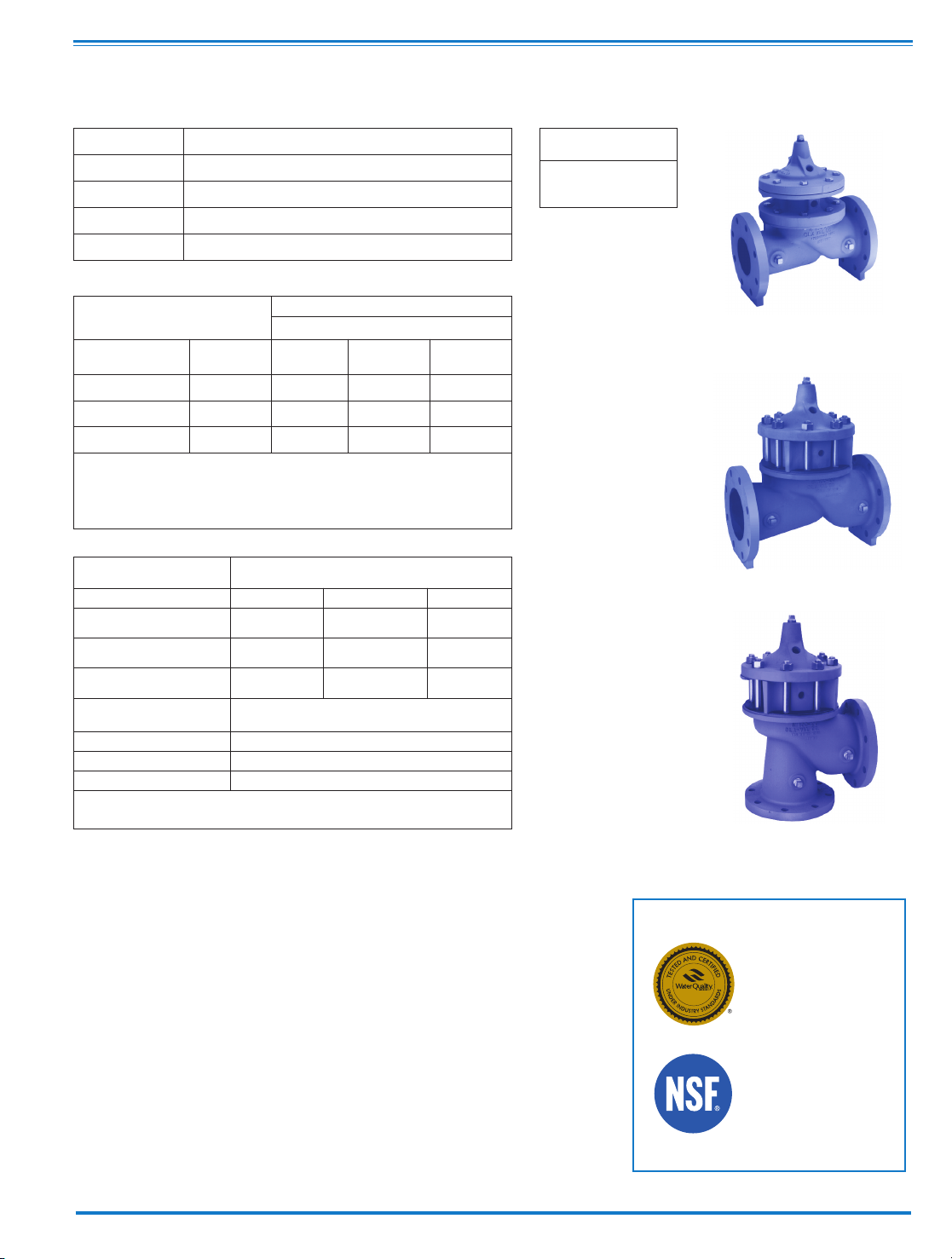
• Reduced Cavitation Design
• Drip-tight, Positive Seating
• Service Without Removal From Line
• Globe or Angle Pattern
• Every Valve Factory-Tested
600 Series
Powertrol Valve
The Cla-Val Model 100-21 is a hydr au lically operated,
diaphragm actuated, globe or angle pattern valve. It consists
of four major components: the body, intermediate chamber,
diaphragm assembly and cover. The diaphragm assembly is
the only moving part.
The diaphragm assembly, which is guided top and center by
a precision machined stem, utilizes a non-wicking diaphragm
of nylon fabric bonded with synthetic rubber. The diaphragm
forms a seal between the cover chamber and intermediate
chamber. A synthetic rubber disc retained on three and onehalf sides forms a drip-tight seal with the renewable seat
when pressure is applied above the diaphragm. As pressure
above the diaphragm is relieved and pressure is applied
below the diaphragm, the valve opens wide for full flow. The
rate of closing or opening can be controlled by modulating
the pressure above or below the diaphragm.
The Model 100-21 is recommended where independent
op e rati n g p ress u re is desi r ed. The va l ve's pa c kles s
construction and simplicity of design assures a long life and
dependable operation. Available in various materials and in
a wide range of sizes. It's applications are many and varied.
100-21
Principle of Operation
The valve holds any intermediate
position when operating pressure is
equ a l abov e and be l ow th e
diaphragm. A Cla-Val four-way pilot
co n t rol with "l o ck" posi t ion can
maintain this balance by stopping
flow in the pilot control system.
Modulating Action
4 - Way Control
4 - Way Control
4 - Way Control with lock
MODEL
see page 2 for
approvals
Page 12
100-21 Powertrol Main Valve Specifications
4"/100 mm Globe, Flanged
6"/150 mm Globe, Flanged
6"/150 mm Angle, Flanged
Options
Epoxy Coating - suffix KC
An FDA approved fusion bonded epoxy
coating for use with cast iron, ductile iron
or steel valves. This coating is resistant to
various water conditions, certain acids,
chemicals, solvents and alkalies. Epoxy
coatings are applied in accordance with
AWWA coating specifications C116-03.
Do not use with temperatures above 175°F/
80° C.
Viton®Rubber Parts- suffix KB
Opt i onal d i aphr a g m, di s c and o-ri n g
fabric at ed w ith Viton®synthe ti c ru bber.
Viton®is well suited for use with mineral
aci d s, salt solu t ions , chl o rina t e d
hydrocarbons, and petroleum oils; and is
pri m aril y use d i n hig h t e m pera t ure
applications up to 250° F/120
°C
. Do not
use with epoxy coating above 175°F/
80° C
.
Heavy Spring
-
suffix KH
The heavy sp ring op tion is used in
applications where there is low differential
pre s sure ac r o ss t h e va lve, an d th e
additional spring force is needed to help the
valve close. This option is best suited for
valv es used in on-off (non- mo dulat ing)
service.
For assistance in selecting appropriate
valve options or valves manufactured
with special design requirements, please
contact our Regional Sales Office or
Factory.
Operating Temp. Range
Fluids
-40° to 180° F
-40° to 82° C
Component Standard Material Combinations
Body & Cover Ductile Iron Cast Steel Bronze
Available Sizes (inches) 3" - 30" 3" - 16" 3" - 16"
Available sizes (mm) 80 - 750 mm 80 - 400 mm 80 - 400 mm
Disc Retainer &
Diaphragm Washer
Cast Iron Cast Steel Bronze
Trim: Disc Guide,
Seat & Cover Bearing
Bronze is Standard
Stainless Steel is optional
Disc Buna-N®Rubber
Diaphragm Nylon Reinforced Buna-N®Rubber
Stem, Nut & Spring Stainless Steel
For material options on sizes not listed, consult factory.
Cla-Val manufactures valves in more than 50 different alloys.
Materials
A
vailable Sizes
Pattern Flanged
Globe (inches) 3", 4", 6", 8", 10", 12", 14", 16", 18", 20", 24", 30"
Globe (mm) 80mm - 750mm (all sizes)
Angle (inches) 4", 6", 8"
Angle (mm) 100, 150 and 200 mm
Pressure Ratings
(Recommended Maximum Pressure - psi)
Valve Body & Cover
Pressure Class
Flanged
Grade Material
ANSI
Standards*
150
Class
300
Class
ASTM A536 Ductile Iron B16.42 250 400
ASTM A216-WCB Cast Steel B16.5 285 400
UNS 87850 Bronze B16.24 225 400
Note: * ANSI standards are for flange dimensions only.
Flanged valves are available faced but not drilled.
Valves for higher pressure are available; consult factory for details
NSF International
recognizes Cla-Val
as complying with
NSF/ANSI 61 and all
applicable
requirements.
NSF/ANSI 372:
National Lead Free
Mandate “Reduction
of Lead in Drinking
Water Act”
Approvals
Page 13
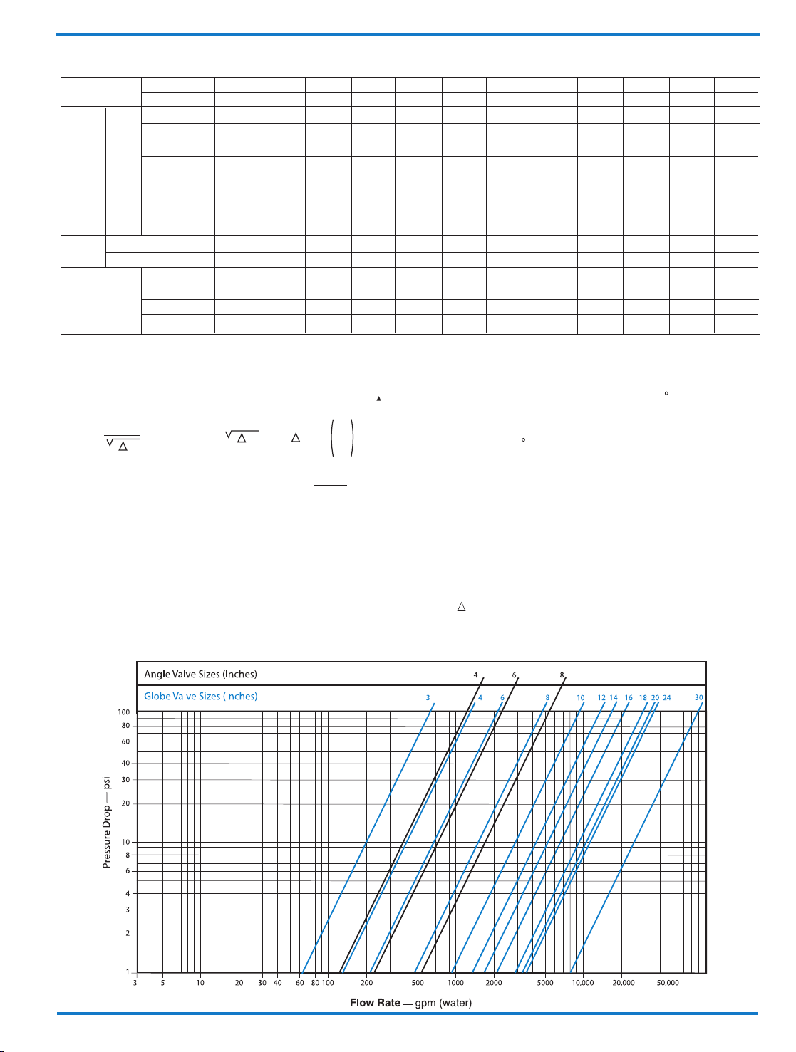
Model 100-21 Flow Chart (Based on normal flow through a wide open valve)
K =
894d
4
C
2
v
L =
K
12 f
K Factor (Resistance Coefficient)
The Value of K is calculated from the formula:
(U.S. system units)
Equivalent Length of Pipe
Equivalent lengths of pipe (L) are determined from the formula:
(U.S. system units)
Fluid Velocity
Fluid velocity can be calculated from the following formula:
(U.S. system units)
d
V =
.4085 Q
2
d
C
V
Factor
Formulas for computing C Factor, Flow (Q) and Pressure Drop
V
(
P):
C
V
=
Q
P
C
V
=
Q
P
C
V
=
Q
P
2
V
Where:
U.S. (gpm) @ 1 psi differential at 60 F water
(l/s) @ 1 bar (14.5 PSIG) differential
or
at 15 C water
inside pipe diameter of Schedule 40 Steel Pipe (inches)
friction factor for clean, new Schedule 40 pipe
(dimensionless) (from Cameron Hydraulic Data,
18th Edition, P 3-119)
Resistance Coefficient (calculated)
Equivalent Length of Pipe (feet)
Flow Rate in U.S. (gpm) or (l/s)
Fluid Velocity (feet per second) or (meters per second)
Pressure Drop in (psi) or (bar)
=
=
=
=
=
=
=
=
=
P
V
Q
L
K
f
d
C
3
8
0
6
2
1
5
—
—
293
8
9.3
—
—
2
0.6
—
—
.032
—
.
12
4
1
00
1
36
3
2.5
135
32
251
7
6.4
2
54
7
7.6
1
2.7
12.9
—
.08
—
.
30
6
1
50
2
29
5
5
233
56
777
2
37.1
7
51
2
29
2
3.1
22.3
—
.17
—
.
64
8
2
00
4
80
1
15
545
132
748
2
28.1
5
80
1
76.9
1
5.7
12.2
—
.53
—
2
.0
1
0
2
50
9
30
2
23
—
—
621
1
89.5
—
—
1
0.4
—
—
1.26
—
4
.8
1
2
3
00
1
458
3
50
—
—
654
1
99.4
—
—
8
.5
—
—
2.51
—
9
.5
1
4
3
50
1
725
4
14
—
—
750
228.7
—
—
8
.9
—
—
4
—
15.1
16
4
00
2
110
5
06
—
—
977
298.1
—
—
1
0.2
—
—
4
—
15.1
18
4
60
2
940
7
05
—
—
983
299.9
—
—
8
.4
—
—
9.6
—
36.2
20
5
10
3
400*
8
16
—
—
1125
343.2
—
—
8
.8
—
—
9.6
—
36.2
24
610
3500*
8
40
—
—
3
005
916.6
—
—
1
9.1
—
—
9
.6
—
36.2
30
750
7900*
1
895
—
—
2
130
649.6
—
—
1
0.5
—
—
2
9.0
—
110
G
lobe
Pattern
Angle
Pattern
G
lobe
P
attern
A
ngle
Pattern
E
quivalent
L
ength
of
Pipe
C
V
Factor
Functional Data Model 100-21
*
Estimated
Valve Size
Liquid Displaced
from Diaphragm
Chamber When
V
alve Opens
K
Factor
m
m
Gal./Min. (gpm.)
Litres/Sec. (l/s.)
Gal./Min. (gpm.)
L
itres/Sec. (l/s.)
F
eet (ft.)
M
eters (m.)
F
eet (ft.)
Meters (m.)
Fl. Oz
U
.S. Gal.
m
l
L
itres
I
nches
Globe Pattern
Angle Pattern
Page 14

CLA-VAL
1701 Placentia Ave • Costa Mesa CA 92627 • Phone: 949-722-4800 • Fax: 949-548-5441 • E-mail: info@cla-val.com • www.cla-val.com
Copyright Cla-Val 2017 • Printed in USA • Specifications subject to change without notice.
©
EE
D
E
Inlet
DD
AA
100-21
Flanged
F
A
C
(MAX)
K
J
H
Inlet
Outlet
FF
B
(Diameter)
Cla-Val 100-21 Powertrol Main Valve Dimensions
Service and Installation
Cla-Val Control Valves operate with maximum efficiency when mounted in horizontal piping with the main valve cover UP, however, other
positions are acceptable. Due to component size and weight of 10 inch/250 mm and larger valves, installation with cover UP is advisable. We
recommend isolation valves be installed on inlet and outlet for maintenance. Adequate space above and around the valve for service personnel
should be considered essential. A regular maintenance program should be established based on the specific application data. However, we
recommend a thorough inspection be done at least once a year. Consult factory for specific recommendations.
E-100-21 (R-12/2017)
Valve Size (Inches)
A 150 ANSI
A
A 300 ANSI
B
Diameter
C Maximum
D 150 ANSI
DD 300 ANSI
E
EE 300 ANSI
F 150 ANSI
150 ANSI
FF 300 ANSI
H NPT Body Tapping
J NPT Cover Center Plug
K NPT Cover Tapping
Stem Travel
Approx. Ship Weight (lbs)
13.88
14.50
9.12
1
1.75
6
.94
7.25
5.50
5.81
4.50
5.00
0.50
0.50
0.50
0.80
135
4
1
7.75
1
8.62
1
1.50
15.25
8.88
9.38
6.75
7.25
5.50
6.25
0.75
0.75
0.75
1.10
230
6
8
21.38
22.38
15.75
2
0.25
10.69
11.19
7.25
7.75
6.75
7.50
0.75
0.75
0.75
1.70
480
1
2
3
0.00
3
1.50
2
3.62
27.25
9.50
10.25
1.00
1.00
1.00
2.80
1410
—
1
4
3
4.25
35.75
2
8.00
29.31
11.00
1.00
1.25
1.00
3.40
2215
—
1
8
42.12
4
3.62
3
5.44
35.00
15.88
15.88
1.00
2.00
1.00
4.50
2300
—
—
—
—
10.25
1
1.00
6
.62
9.25
3.25
4.12
0.38
0.50
0.38
0.60
70
3
—
—
—
—
—
—
—
—
—
—
1
6
3
5.00
3
6.62
28.00
34.12
11.75
12.75
1.00
1.25
1.00
3.40
2215
—
—
—
—
—
—
—
—
—
—
—
1
0
2
6.00
2
7.38
20.00
2
3.75
8.00
8.75
1.00
1.00
1.00
2.30
785
—
—
—
——
2
0
48.00
49.62
3
5.44
40.25
14.56
16.06
1.00
2.00
1.00
4.50
3400
—
—
—
24
48.00
4
9.75
3
5.44
40.25
17.00
19.00
1.00
2.00
1.00
4.50
3600
—
30
63.25
53.19
5
6.50
19.88
1.00
2.00
1.00
6.50
7700
—
—
—
Valve Size (Inches)
A
150 ANSI
AA 300 ANSI
B
Diameter
C Maximum
D 150 ANSI
DD 300 ANSI
E
EE 300 ANSI
F 150 ANSI
150 ANSI
FF 300 ANSI
H NPT Body Tapping
J NPT Cover Center Plug
K NPT Cover Tapping
Stem Travel
Approx. Ship Weight (lbs)
13.88
1
4.50
9
.12
11.75
6.94
7.25
5.50
5.81
4.50
5.00
0.50
0.50
0.50
0.80
135
4
1
7.75
1
8.62
11.50
1
5.25
8.88
9.38
6.75
7.25
5.50
6.25
0.75
0.75
0.75
1.10
230
6
8
21.38
22.38
1
5.75
20.25
10.69
11.19
7.25
7.75
6.75
7.50
0.75
0.75
0.75
1.70
480
12
30.00
31.50
23.62
2
7.25
9.50
10.25
1.00
1.00
1.00
2.80
1410
—
1
4
3
4.25
3
5.75
2
8.00
29.31
11.00
1.00
1.25
1.00
3.40
2215
—
18
4
2.12
43.62
35.44
3
5.00
15.88
15.88
1.00
2.00
1.00
4.50
2300
—
—
—
—
1
0.25
11.00
6.62
9.25
3.25
4.12
0.38
0.50
0.38
0.60
70
3
—
—
—
—
—
—
—
—
—
—
1
6
3
5.00
36.62
28.00
34.12
11.75
12.75
1.00
1.25
1.00
3.40
2215
—
—
—
—
—
—
—
—
—
—
—
10
26.00
27.38
20.00
2
3.75
8.00
8.75
1.00
1.00
1.00
2.30
785
—
—
—
——
2
0
48.00
4
9.62
3
5.44
40.25
14.56
16.06
1.00
2.00
1.00
4.50
3400
—
—
—
2
4
4
8.00
4
9.75
35.44
40.25
17.00
19.00
1.00
2.00
1.00
4.50
3600
—
3
0
6
3.25
5
3.19
56.50
19.88
1.00
2.00
1.00
6.50
7700
—
—
—
Valve Size (Inches)
A 150 ANSI
AA 300 ANSI
B Diameter
C Maximum
D 150 ANSI
DD 300 ANSI
E
EE 300 ANSI
F 150 ANSI
150 ANSI
FF 300 ANSI
H NPT Body Tapping
J NPT Cover Center Plug
K NPT Cover Tapping
Stem Travel
Approx. Ship Weight (lbs)
13.88
14.50
9.12
11.75
6.94
7.25
5.50
5.81
4.50
5.00
0.50
0.50
0.50
0.80
135
4
17.75
18.62
11.50
15.25
8.88
9.38
6.75
7.25
5.50
6.25
0.75
0.75
0.75
1.10
230
68
21.38
22.38
15.75
20.25
10.69
11.19
7.25
7.75
6.75
7.50
0.75
0.75
0.75
1.70
480
12
30.00
31.50
23.62
27.25
9.50
10.25
1.00
1.00
1.00
2.80
1410
—
14
34.25
35.75
28.00
29.31
11.00
1.00
1.25
1.00
3.40
2215
—
18
42.12
43.62
35.44
35.00
15.88
15.88
1.00
2.00
1.00
4.50
2300
—
—
—
—
10.25
11.00
6.62
9.25
3.25
4.12
0.38
0.50
0.38
0.60
70
3
—
—
—
—
—
—
—
—
—
—
16
35.00
36.62
28.00
34.12
11.75
12.75
1.00
1.25
1.00
3.40
2215
—
—
—
—
—
—
—
—
—
—
—
10
26.00
27.38
20.00
23.75
8.00
8.75
1.00
1.00
1.00
2.30
785
—
—
—
——
20
48.00
49.62
35.44
40.25
14.56
16.06
1.00
2.00
1.00
4.50
3400
—
—
—
24
48.00
49.75
35.44
40.25
17.00
19.00
1.00
2.00
1.00
4.50
3600
—
30
63.25
53.19
56.50
19.88
1.00
2.00
1.00
6.50
7700
—
—
—
Valve Size (mm)
A 150 ANSI
AA 300 ANSI
B Diameter
C Maximum
D 150 ANSI
DD 300 ANSI
E
EE 300 ANSI
F 150 ANSI
150 ANSI
FF 300 ANSI
H NPT Body Tapping
J NPT Cover Center Plug
K NPT Cover Tapping
Stem Travel
Approx. Ship Weight (kgs)
353
368
232
298
176
184
140
148
114
127
0.50
0.50
0.50
20
61
100
451
473
292
387
226
238
171
184
140
159
0.75
0.75
0.75
28
104
150 200
543
568
400
514
272
284
184
197
171
191
0.75
0.75
0.75
43
218
450
1070
1108
900
889
403
403
1.00
2.00
1.00
86
1044
—
—
—
—
260
279
168
235
95
105
0.38
0.50
0.38
15
32
80
—
—
—
—
400
889
930
711
867
298
324
1.00
1.25
1.00
86
1006
—
—
—
—
350
870
908
711
744
279
1.00
1.25
1.00
86
1006
—
—
—
—
—
300
762
800
600
692
241
260
1.00
1.00
1.00
71
640
—
—
—
—
250
660
695
508
603
203
222
1.00
1.00
1.00
58
356
—
—
—
——
500
1219
1260
900
1022
370
408
1.00
2.00
1.00
114
1544
—
—
—
—
—
—
600
1219
1264
900
1022
432
483
1.00
2.00
1.00
114
1634
—
—
—
—
750
1607
1351
1435
505
1.00
2.00
1.00
165
3496
—
—
—
Page 15

DESCRIPTION
Bulletin 8210’s are 2-way, normally closed internal pilot operated solenoid
valves. Valve bodies and bonnets are of brass construction. Standard
valves have a General Purpose, NEMA Type 1 Solenoid Enclosure.
Bulletin 8211’s are the same as Bulletin 8210’s except the solenoids are
equipped with an enclosure which is designed to meet NEMA Type 4,
Watertight, NEMA Type 7 (C or D) Hazardous Locations - Class 1, Group
C or D and NEMA Type 9 (E, For G) Hazardous Locations - Class 2,
Groups E, F or G. The Explosion-Proof/Watertight Solenoid Enclosures
are shown on separate sheets of installation and Maintenance
Instructions, Form Numbers V-5380 and V-5391.
OPERATION
Normally Closed: Valve is closed when solenoid is de-energized and
opens when solenoid is energized.
MANUAL OPERATOR
(Optional)
Valves with Suffix ‘MO’ in the catalog number are provided with a manual
operator which allows manual operation when desired or during an
interruption of electrical power. To operate valve manually, push in
knurled cap and rotate clockwise 180° Disengage manual operator by
rotating knurled cap counterclockwise 180° before operating electrically.
MANUAL OPERATOR LOCATION
(Refer to Figures 1 and 3)
Manual operator (when shipped from factory) will be located over the valve
outlet. Manual operator may be relocated at 90° increments by rotating valve
bonnet. Remove bonnet screws (4) and rotate valve bonnet with solenoid to
desired position. Replace bonnet screws (4) and torque in a crisscross
manner to 110 ± 10 inch pounds.
If valve is installed in the system and is operational, proceed in the
following manner:
WARNING:
Depressurize valve and turn off electrical
power supply.
1. Remove retaining cap or clip and slip the entire solenoid enclosure off
the solenoid base sub-assembly.
CAUTION:
When metal retaining clip
disengages, it will spring upwards.
2. Remove bonnet screws (4) and rotate valve bonnet to desired position.
3. Replace bonnet screws (4) and torque in a crisscross manner to 110 ±
10 inch pounds. Replace solenoid enclosure and retaining clip or cap.
INSTALLATION
Check nameplate for correct catalog number, pressure, voltage and
service.
TEMPERATURE LIMITATIONS
For maximum valve ambient and fluid temperatures, refer to chart. The
temperature limitations listed are for UL applications. For non-UL
applications, higher ambient and fluid temperature limitations are
available. Consult factory, Check catalog number on nameplate to
determine maximum temperatures.
POSITIONING/MOUNTING
This valve is designed to perform properly when mounted in any position.
However, for optimum life and performance, the solenoid should be
mounted vertical and upright so as to reduce the possibility of foreign
matter accumulating in the core tube area. For mounting bracket (optional
feature) dimensions, refer to Figure 2.
PIPING
Connect piping to valve according to markings on valve body. Apply pipe
compound sparingly to male pipe threads only; if applied to valve threads,
it may enter the valve and cause operational difficulty. Pipe strain should
be avoided by proper support and alignment of piping. When tightening
the pipe, do not use valve as a lever, Wrenches applied to valve body or
piping are to be located as close as possible to connection point.
IMPORTANT:
For the protection of the solenoid valve, install a strainer or
filter suitable for the service involved in the inlet side as close to the valve
as possible. Periodic cleaning Is required depending on the service
conditions. See Bulletins 8600, 8601 and 8602 for strainers.
WIRING
Wiring must comply with Local and National Electrical Codes. Housings
for all solenoids are provided with connections for 1/2 inch conduit. The
general purpose solenoid enclosure may be rotated to facilitate wiring by
removing the retaining cap or clip.
CAUTION:
When metal retaining clip
disengages, it will spring upwards. Rotate to desired position. Replace
retaining cap or clip before operating.
NOTE:
Alternating Current (A-C) and Direct Current (D-C) solenoids are
built differently. To convert from one to the other, It Is necessary to
change the complete solenoid including the solenoid base sub-assembly
and core assembly.
SOLENOID TEMPERATURE
Standard catalog valves are supplied with coils designed for continuous
duty service. When the solenoid is energized for a long period, the
solenoid enclosure becomes hot and can be touched with the hand only
for an instant. This is a safe operating temperature. Any excessive heating
will be indicated by the smoke and odor of burning coil insulation.
MAINTENANCE
WARNING:
Turn off electrical power supply and depressurize valve
before making repairs. It Is not necessary to remove the valve from the
pipe line for repairs.
CLEANING
A periodic cleaning of all solenoid valves is desirable. The time between
cleanings will vary, depending on media and service conditions. In
general, if the voltage to the coil is correct, sluggish valve operation,
excessive leakage or noise will indicate that cleaning is required.
PREVENTIVE MAINTENANCE
1. Keep the medium flowing through the valve as free from dirt and
foreign material as possible.
2. While in service, operate the valve at least once a month to insure
proper opening and closing.
3. Periodic inspection (depending on media and service conditions) of
internal valve parts for damage or excessive wear is recommended.
Thoroughly clean all parts, Replace any parts that are worn or damaged.
Construction
A-C Construction
(Alternating Current)
D-C Construction
(Direct Current)
Coil
Class
A
F
H
A, F
or H
Catalog
Number
Prefix
None or
DA
DF or
FT
HT
None, FT
or HT
Max.
Ambient
Temp.
°F
77
122
140
77
Max.
Fluid
Temp.
°F
180
180
180
150
INSTALLATION AND
MAINTENANCE INSTRUCTIONS
2-WAY INTERNAL PILOT OPERATED SOLENOID VALVES
DIAPHRAGM TYPE - 3/8, 1/2 AND 3/4 N.P.T.
NORMALLY CLOSED OPERATION
BULLETINS
8210
8211
ASCO
FORM NO. V-5848
Page 16

IMPROPER OPERATION
1. Faulty Control Circuit: Check the electrical system by energizing the
solenoid. A metallic click signifies that the solenoid is operating. Absence
of the click indicates loss of power supply. Check for loose or blown-out
fuses. open circuited or grounded coil. broken lead wires or splice
connections.
2. Burned-Out Coil: Check for open circuited coil. Replace coil if necessary.
3. Low Voltage: Check voltage across coil leads. Voltage must be at
least 85% of nameplate rating.
4. Incorrect Pressure: Check valve pressure. Pressure to valve must be
within range specified on nameplate.
5. Excessive Leakage: Disassemble valve and clean all parts. Replace
worn or damaged parts with a complete Spare Parts Kit for best results.
COIL REPLACEMENT
(Refer to Figures 1, 2 and 3)
Turn off electrical power supply and disconnect coil lead wires.
Proceed In the following manner:
1. Remove retaining cap or clip, nameplate and cover.
CAUTION:
When
metal retaining clip disengages. it will spring upwards.
2. Slip yoke containing coil, sleeves and insulating washers off the
solenoid base sub-assembly. For D-C Construction. slip spring washer.
coil and insulating washers off the solenoid base sub-assembly. Insulating
washers are omitted when a molded coil is used.
3. Reassemble in reverse order of disassembly paying careful attention
to exploded views provided for identification and placement of parts.
CAUTION:
Solenoid must be fully reassembled as the housing and
internal parts are part of and complete the magnetic circuit. Place
insulating washers at each end of con, If required.
VALVE DISASSEMBLY
Depressurize valve and turn off electrical power supply. For A-C
Construction, refer to Figures 1 and 2. For D-C Construction, refer to
Figure 3. Proceed In the following manner:
1. Disassemble valve in an orderly fashion. Pay careful attention to
exploded views provided for identification of parts.
2. Remove retaining cap or clip and slip the entire solenoid enclosure off
the solenoid base sub-assembly.
CAUTION:
When metal retaining clip
disengages, it will spring upwards.
3. Unscrew solenoid base sub-assembly and remove bonnet gasket.
Core assembly and core spring.
4. For A-C Construction without manual operator. remove valve bonnet
screws (4). Remove solenoid base sub-assembly. core assembly and
core spring.
5. Remove diaphragm spring (A-C Construction only). diaphragm
assembly and body gasket.
6. For normal maintenance, it is not necessary to disassemble the
manual operator unless external leakage is evident To disassemble,
remove stem pin. manual operator stem. stem spring and stem gasket.
7. All parts are now accessible for cleaning or replacement. Replace
worn or damaged parts with a complete Spare Parts Kit for best results.
VALVE REASSEMBLY
1. Reassemble in reverse order of disassembly paying careful attention
to exploded views provided for identification and placement of parts.
2. Replace body gasket and diaphragm assembly. Locate bleed hole in
diaphragm assembly approximately 45° from valve outlet.
3. Replace valve bonnet and bonnet screws. Torque bonnet screws (4) in
a crisscross manner to 110 ± 10 inch pounds.
4. For A-C Construction, the diaphragm spring. core assembly and core
spring must be installed prior to assembly of bonnet as this is the solenoid
base sub-assembly. Be sure diaphragm spring is installed properly.
Closed turns of spring to seat on diaphragm assembly. For valves with a
manual operator (see Figure 1), the small end of diaphragm spring seats
on diaphragm assembly.
5. Install core spring in core assembly. Be sure core spring is inserted
into core assembly with wide end in first. Closed end protrudes from top of
core assembly.
6. Replace bonnet gasket, core assembly, core spring and solenoid base
sub-assembly. Torque solenoid base sub-assembly to 175 ± 25 inch pounds
7. If removed, replace manual operator stem gasket. stem spring, stem
and stem pin.
8. Replace solenoid enclosure and retaining cap or clip.
9. After maintenance, operate the valve a few times to be sure of proper
opening and closing.
ORDERING INFORMATION
FOR SPARE PARTS KITS
When Ordering Spare Parts Kits or Coils
Specify Valve Catalog Number,
Serial Number and Voltage
Spare Parts Kits
Spare Parts Kits and Coils are available for ASCO valves.
Parts marked with an (*) are supplied in Spare Parts Kits
Bulletin 8210 -- A-C Construction
Manual Operator
(Catalog Number Suffixed “MO”)
Figure 1.
Page 17

Bulletin 8210 -- A-C Construction
General Purpose Solenoid Enclosure Shown
For Explosion-Proof/Watertight Solenoid Enclosure used on Bulletin 8211, see Form No. V-5391.
Figure 2.
Page 18

CLA-VAL
Copyright Cla-Val 2011 Printed in USA Specifications subject to change without notice.
P.O. Box 1325 • Newport Beach, CA 92659-0325 • Phone: 949-722-4800 • Fax: 949-548-5441 • E-mail: claval@cla-val.com • Website cla-val.com
©
N-V5848 (R-3/2011)
Bulletin 8210 -- D-C Construction
General Purpose Solenoid Enclosure Shown
For Explosion-Proof/Watertight Solenoid Enclosure used on Bulletin 8211, see Form No. V-5390.
Figure 3.
Page 19

DESCRIPTION
Bulletin 8262’s are 2-way normally closed, direct acting solenoid valves
having bodies of brass construction. Standard valves have a General
Purpose NEMA Type 1 Solenoid Enclosure. Valves may also be equipped
with a solenoid enclosure which is designed to meet NEMA Type 4
Watertight, NEMA Type 7 (C or D) Hazardous Locations-Class 1, Groups C
or D and NEMA Type 9 (E, For G) Hazardous Locations Class 2, Groups E, F
or G. Installation and Maintenance Instructions for Explosion-Proof/Watertight
Solenoid Enclosures are shown on Form Nos. V-5391 or V-5380.
OPERATION
Normally Closed: Valve is closed when solenoid is de-energized. Valve
opens when solenoid is energized.
NOTE:
Inlet port will either be marked “1” or “1N.” Outlet port will be marked “2.”
IMPORTANT:
No minimum operating pressure required.
INSTALLATION
Check nameplate for correct catalog number, pressure, voltage and service.
TEMPERATURE LIMITATIONS
For maximum valve ambient and fluid temperature, refer to chart below. For
higher ambient and fluid temperatures, consult factory. Check catalog number
and watt rating on nameplate to determine the maximum temperatures.
POSITIONING
Valve is designed to perform properly when mounted in any position.
However, for optimum life and performance, the solenoid should be
mounted vertical and upright so as to reduce the possibility of foreign
matter accumulating in the core tube area.
MOUNTING
For valve body and mounting bracket mounting dimensions, refer to
Figures 1 and 2.
PIPING
Connect piping according to markings on valve body. Apply pipe
compound sparingly to male pipe threads only; if applied to valve threads,
it may enter valve and cause operational difficulty. Pipe strain should be
avoided by proper support and alignment of piping. When tightening the
pipe, do not use valve as a lever. Wrenches applied to valve body or
piping are to be located as close as possible to connection point.
IMPORTANT:
For the protection of the solenoid valve. install a strainer or
filter suitable for the service involved in the inlet side as close to the valve
as possible. Periodic cleaning is required depending upon service
conditions. See Bulletins 8600, 8601 and 8602 for strainers.
WIRING
Wiring must comply with Local and National Electrical Codes. Solenoid
housings are provided with a 7/8 diameter hole for 1/2 inch conduit. The
general purpose solenoid enclosure may be rotated to facilitate wiring by
removing the retaining cap or clip.
CAUTION:
When metal retaining clip
disengages, it will spring upward. Rotate enclosure to desired position.
Replace retaining cap or clip before operating.
NOTE:
Alternating Current (A-C) and Direct Current (D-C) solenoids are
built differently. To convert from one to the other, it is necessary to change
the complete solenoid including the core assembly and solenoid base
sub-assembly.
SOLENOID TEMPERATURE
Standard catalog valves are supplied with coils designed for continuous
duty service. When the solenoid is energized for a long period, the
solenoid enclosure becomes hot and can be touched with the hand only
for an instant. This is a safe operating temperature. Any excessive heating
will be indicated by the smoke and odor of burning coil insulation.
MAINTENANCE
WARNING:
Turn off electrical power supply and depressurize valve
before making repairs. It is not necessary to remove the valve from the
pipe line for repairs.
CLEANING
A periodic cleaning of all solenoid valves is desirable. The time between
cleanings will vary depending upon media and service conditions in
general, if the voltage to the coil is correct. sluggish valve operatIon,
excessive noise or leakage will indicate that cleaning is required. Clean
valve strainer or filter when cleaning solenoid valve.
PREVENTIVE MAINTENANCE
1. Keep the medium flowing through the valve as free from dirt and
foreign material as possible.
2. While in service, operate the valve at least once a month to insure
proper opening and closing.
3. Periodic inspection (depending on media and service conditions) of
internal valve parts for damage or excessive wear is recommended
Thoroughly clean all parts. Replace any parts that are worn or damaged.
IMPROPER OPERATION
1. Faulty Control Circuit: Check the electrical system by energizing the
solenoid. A metallic click signifies the solenoid is operating. Absence of
the click indicates loss of power supply. Check for loose or blownout
fuses, open-circuited or grounded coil, broken lead wires or splice
connections.
2. Burned-Out Coil: Check for open-circuited coil. Replace coil if necessary.
3. Low Voltage: Check voltage across the coil leads. Voltage must be at
least 85% of nameplate rating.
4. Incorrect Pressure: Check valve pressure. Pressure to valve must be
within range specified on nameplate.
5. Excessive Leakage: Disassemble valve and clean all parts. Replace
worn or damaged parts with a complete Spare Parts Kit for best results.
COIL REPLACEMENT
Turn off electrical power supply and disconnect coil lead wires. Refer to
watt rating stamped on nameplate for identification of solenoid
construction. When you have determined the watt rating of solenoid,
select the correct paragraph below.
FIGURE 3 SHOWS A SOLENOID WITH A WATT RATING OF 6 A-C, 9.7 D.C,OR 9 A-C.
1. Remove retaining cap or clip, nameplate and cover.
CAUTION:
When
metal retaining clip disengages, it will spring upward.
2. Slip the yoke containing a coil, sleeves and insulating washers off the
solenoid base sub-assembly. Insulating washers are omitted when a
molded coil is used.
3. Slip coil, sleeves and insulating washers from yoke. 4. Reassemble in
reverse order of disassembly paying careful attention to exploded view
provided for identification and placement of parts.
Wattage
Coil
Class
Catalog
Number
Prefix
Max.
Ambient
Temp.
°F
Max.
Fluid
Temp.
°F
INSTALLATION AND
MAINTENANCE INSTRUCTIONS
2-WAY DIRECT ACTING SOLENOID VALVES
NORMALLY CLOSED OPERATION -- 1/4 N.P.T.
BULLETINS
8262
ASCO
FORM NO. V-5927
*Catalog Nos. 8262C200 and 8262B200 and valves with suffix
“W” in the catalog number are limited to 140°F fluid temperature.
16.7*
F
None
77 200
11.2*
A, F
or H
None, FT
or HT
77 150
9.7
A, F
or H
None, FT
or HT
77 120
9
F
None
77 180
A
None
77 180
6
F
FT
122 200
H
HT
140 200
Page 20

ORDERING INFORMATION
FOR SPARE PARTS KITS
When Ordering Spare Pans Kits or Coils,
Specify Valve Catalog Number,
Serial Number and Voltage.
SPARE PARTS KITS
Spare Parts Kits and Coils arc available for ASCO valves.
Parts marked with an asterisk (*) are supplied in Spare Parts Kit.
FIGURE 4 SHOWS A SOLENOID WITH A WATT RATING OF 105 A-C,
11.2 D.C OR 16.7 A.C
1. Remove retaining cap or clip, nameplate and housing.
CAUTION:
When metal retaining clip disengages, it will spring upward.
2. Slip spring washer, insulating washer and coil off the solenoid base
sub-assembly. Insulating washers are omitted when a molded coil is used.
3. Reassemble in reverse order of disassembly paying careful attention
to exploded views provided for identification and placement of parts.
CAUTION:
Solenoid must be fully reassembled as the housing and
internal parts are part of and complete the magnetic circuit. Place an
insulating washer at each end of coil, if required.
VALVE DISASSEMBLY AND REASSEMBLY
Depressurize valve and turn off electrical power supply. For valves with a
watt rating of 6 A-C, 9.7 D-C or 9 A-C, refer to Figure 3. For valves with a
watt rating of 10.5 A-C, 11.2 D-C or 16.7 A-C, refer to Figure 4.
Proceed in the following manner:
1. Remove retaining cap or clip and slip the entire solenoid enclosure off
the solenoid base sub-assembly.
CAUTION:
When metal retaining clip
disengages, it will spring upward.
2. Unscrew solenoid base sub-assembly and remove core assembly,
core spring and body gasket.
3. All parts are now accessible for cleaning or replacement. Replace
worn or damaged parts with a complete Spare Pans Kit for best results.
4. Reassemble in reverse order of disassembly paying careful attention
to exploded views provided for identification and placement of pans.
5. Replace body gasket, core assembly, core spring and solenoid base
sub-assembly. Torque solenoid base sub-assembly to 175 ± 25 inch pounds.
6. After maintenance, operate the valve a few times to be sure of proper
operation.
Figure 1
Body Molding
Figure 2
Mounting Bracket
Mounting Dimensions
Page 21

NOTE: A-C (ALTERNATING CURRENT) CONSTRUCTION SHOWN. FOR A-C CONSTRUCTION,
EITHER END OF THE SPRING MAY BE INSTALLED INTO TOP OF CORE ASSEMBLY. FOR D-C
(DIRECT CURRENT) CONSTRUCTION, INSTALL WIDE END OF CORE SPRING IN CORE ASSEMBLY
FIRST, CLOSED END OF CORE SPRING PROTRUDES FROM TOP OF CORE ASSEMBLY.
Figure 3
Bulletin 8262 (6 A-C, 9.7 D-C or 9 Watts A-C)
General Purpose Solenoid Enclosure Shown
For Explosion-Proof/Watertight Solenoid Enclosure, See Form No. V-5391
Page 22

CLA-VAL
Copyright Cla-Val 2011 Printed in USA Specifications subject to change without notice.
P.O. Box 1325 • Newport Beach, CA 92659-0325 • Phone: 949-722-4800 • Fax: 949-548-5441 • E-mail: claval@cla-val.com • Website cla-val.com
©
N-V5927 (R-3/2010)
Figure 3
Bulletin 8262 (10.5 A-C, 11.2 D-C or 16.7 Watts A-C)
General Purpose Solenoid Enclosure Shown
For Explosion-Proof/Watertight Solenoid Enclosure, See Form No. V-5380
Page 23

CLA-VAL
Copyright Cla-Val 2011 Printed in USA Specifications subject to change without notice.
P.O. Box 1325 • Newport Beach, CA 92659-0325 • Phone: 949-722-4800 • Fax: 949-548-5441 • E-mail: claval@cla-val.com • Website cla-val.com
©
PL-CK2 (R-3/2011)
Page 24

Page 25

CLA-VAL
Copyright Cla-Val 2018 Printed in USA Specifications subject to change without notice.
1701 Placentia Ave • Costa Mesa CA 92627 Phone: 949-722-4800 • Fax: 949-548-5441 • E-mail: info@cla-val.com • www.cla-val.com
©
INSTALLATION / OPERATION / MAINTENANCE
Flow Control
CV
MODEL
N-CV (R-06/2018)
DESCRIPTION
The CV Control is an adjustable restriction which acts as a
needle valve when flow is in the direction of the stem. When
flow is in the reverse direction, the port area opens fully to
allow unrestricted flow. When installed in the control system of
a Cla-Val automatic valve, it can be arranged to function as
either an opening or closing speed control.
OPERATION
The CV Flow Control permits full flow from port A to B, and
restricted flow in the reverse direction. Flow from port A to B
lifts the disc from seat, permitting full flow. Flow in the reverse
direction seats the disc, causing fluid to pass through the clearance between the stem and the disc. This clearance can be
increased, thereby increasing the restricted flow, by screwing
the stem out, or counter-clockwise. Turning the stem in, or
clockwise reduces the clearance between the stem and the
disc, thereby reducing the restricted flow.’
INSTALLATION
Install the CV Flow Control as shown in the valve schematic
All connections must be tight to prevent leakage.
DISASSEMBLY
Follow the sequence of the item numbers assigned to the
parts in the cross sectional illustration for recommended
o
rder of disassembly.
Use a scriber, or similar sharp-pointed tool to remove O-ring
from the stem.
INSPECTION
Inspect all threads for damage or evidence of crossthreading. Check mating surface of seat and valve disc for
excessive scoring or embedded foreign particles. Check
spring for visible distortion, cracks and breaks. Inspect all
parts for damage, corrosion and cleanliness.
CLEANING
After disassembly and inspection, cleaning of the parts can
begin. Water service usually will produce mineral or lime
deposits on metal parts in contact with water. These
deposits can be cleaned by dipping the parts in a 5-percent
muriatic acid solution just long enough for deposits to dissolve. This will remove most of the common types of
deposits. Caution: use extreme care when handling
acid. If the deposit is not removed by acid, then a fine grit
(400) wet or dry sandpaper can be used with water. Rinse
parts in water before handling. An appropriate solvent can
clean parts used in fueling service. Dry with compressed air
or a clean, lint-free cloth. Protect from damage and dust
until reassembled.
REPAIR AND REPLACEMENT
Minor nicks and scratches may be polished out using a fine
grade of emery or crocus cloth; replace parts if scratches
cannot be removed.
Replace O-ring packing and gasket each time CV Flow
Control is overhauled.
Replace all parts which are defective. Replace any parts
which create the slightest doubt that they will not afford completely satisfactory operation. Use Inspection steps as a
guide.
REASSEMBLY
Reassembly is the reverse of disassembly; no special tools
are required.
TEST PROCEDURE
No testing of the flow Control is required prior to reassembly
to the pilot control system on Cla-Val Main Valve.
Page 26

3/8" Flow Control
CV
2.12
MAX
STAMP PART NO. ON
SMOOTH SURFACE
RESTRICTED
FLOW
3/8 - 18 NPT
1.84
ADJUSTING STEM
(TURN CLOCKWISE TO
INCREASE RESTRICTION)
1
7
2
10
9
8
6
5
4
3
.85
FREE FLOW
BAR STOCK
CONFIGURATION
When ordering parts,
please specify:
• Number Stamped on Side
• Description (CV Flow Control)
• Part Description
• Material
CLA-VAL
Copyright Cla-Val 2018 Printed in USA Specifications subject to change without notice.
1701 Placentia Ave • Costa Mesa CA 92627 Phone: 949-722-4800 • Fax: 949-548-5441 • E-mail: info@cla-val.com • www.cla-val.com
©
PL-CV (R-03/2011)
PARTS LIST
ITEM DESCRIPTION QTY
1
Cap (SS only)
1
2
Nut, Jam
1
3
Seat
1
4
Gasket
1
5
Disc
1
6
Spring
1
7
Ring, Retaining
1
8
Stem
1
9
O-Ring
1
10
Housing
1
Page 27

CALIBRATION
1. When properly adjusted, the transmitter arm TOTAL arc of travel,
as valve moves from full closed to full open will be approximately
60 to 70 degrees. Thus, the transmitter-actuating arm will be horizontal
when the valve is halfway open (approximately 30 degrees up and
30 degrees down). At valve closed position the transmitter will have
a 4 mA output and at fully open position the transmitter will have a
20 mA output.
2. You will need the following tools to calibrate and align the X117C:
A.) A small flat blade screwdriver to fit the span and null
potentiometers.
B.) A ruler for measuring location of transmitter arm and valve
actuating stem and spool.
Valve Position Transmitter
X117C
DESCRIPTION
The Model X117C Valve Position Transmitter is designed to provide
analog signal (4 - 20 mA, 2 wire) output of valve position for Cla-Val
Main Valves. A stem extension is fitted to the main valve stem with
the position transmitter mechanically linked to it. The valve stem is
mechanically linked to the electronics for an output signal that is in
direct proportion to valve position. Optional limit switches (2 SPDT
or 2 DPDT) are provided on the Model X117CLS for signaling when
valve has reached fully open or closed position. Provisions are
made for bleeding air from valve cover through a small bleed screw
and washer located on one wrench flat of adapter.
INSTALLATION
Normally, the X117C is supplied mounted on the Cla-Val main
valve. If X117C has not been installed at factory, then install stem,
adapter, mounting bracket and transmitter (in order) as shown on
drawing 16767. Necessary field setting of the X117C requires
some adjustment to the position of the transmitter relative to the
stem and the spool, so you may need to loosen transmitter on the
bracket. Refer to Drawing No. 16767.
MODEL
INSTALLATION / OPERATION / MAINTENANCE
OPERATION
The signal from the position sensing linkage mechanism is converted
to a two-wire 4 to 20 mA current output appearing at the output
terminals. The voltage compliance range is 12.5 to 40 Volts DC.
Initial resistance will range from 975 ohms at transmitter full overtravel (Valve open) to 500 ohms at transmitter free position (Valve
closed)
Wiring
Orient transmitter and bracket to conduit. Loosen jam nut holding
transmitter and bracket to adapter for connecting transmitter to
field wiring conduit. Tighten jam nut after connection is made. After
unthreading housing from transmitter connect wires to OUTPUT
screw terminals. DO NOT USE HOUSING AS WIRING PULLBOX.
Use good field wiring practices for low voltage DC analog instrumentation wiring (suggest 18-gage multistrand wire minimum).
Avoid potential ground loops. See drawing for typical wiring connections. Calibration of transmitter should be done with a temporary
hookup of test equipment before final wiring connections are
made. The enclosure is NEMA rated 1, 3, 4, 4X, 6, 6P, 7, 9, and 13.
Appropriate measures should be taken to avoid internal condensation.
C.) A 4-20 mA calibration/tester or multiamp-tester/meter or
some means of measuring the 4-20 mA transmitter output,
D.) A small (9/64 inch) hexagon key wrench to fit the transmitter
adjustable roller arm,
E.) A small (3/32 inch) hexagon key wrench to fit the spool
setscrew,
F.) Hand tools to tighten X117C assembly after calibration is
complete.
IMPORTANT CAUTION
: The transmitter does not have overtravel
stops. Use care to insure that rotary travel does not exceed 80
degrees from "center" (free) position in either direction during start
up and operation. Damage to the transmitter could occur.
3. Make preliminary mechanical settings. (Refer to Drawing No.
16767) Be sure that the valve is in the fully closed position. See
Technical Manual for main valve for information on this. Be sure
that line isolation or block valves are closed. Be sure that the
Function Switch in the transmitter is in the “CW” position.
4. Adjust bracket and transmitter to preliminary centerline distance
“C” for valve size. See Table. This is distance between valve actuating
stem centerline (actuates vertically up and down) and transmitter
actuating arm pivot centerline (rotates vertically up and down).
Install spool on actuating stem.
5. Position the actuating arm. With valve in closed position, loosen
setscrews on spool and actuating arm. First, completely loosen
actuating arm adjusting screw to allow the knurled shaft of the
transmitter to return to "center" (free) position. Then, adjust actuating
arm in or out on the knurled shaft so that the actuating arm roller
is making good contact with the lower lip of the spool and does not
contact the center of the spool. The actuating arm should be about
30 degrees down from pivot horizontal centerline.
Page 28

After loosening the setscrew, move the spool by hand (up and
down) to check that the roller and spool are in alignment throughout
entire valve stroke. The actuating arm should not be moved more
than 30 degrees up or down from horizontal centerline of knurled
shaft. The centerline of the roller should not be past the lower lip
or rim of the spool at any valve position. You may have to adjust
the length of the actuating arm when doing this.
You will feel the spring restoring force of the transmitter as you do
this step. This restoring force allows the roller to maintain contact
with the lower lip of the spool throughout the entire valve stroke.
The spool must now be adjusted into place by moving the spool
slightly (approximately 1/4") upward to engage this spring force.
Tighten spool setscrew when the actuating arm is angled about 30
degrees downward.
6. Remove transmitter cover and temporarily connect calibration
wiring equipment (milliamp meter and power supply or portable
instrumentation calibrator/tester to transmitter screw terminals.).
Refer to calibration equipment and adjust potentiometer marked
“NULL” until the meter reads 4 mA. A clockwise turn increases output. Use care in adjusting the potentiometer by not pressing in on
the adjusting stem while turning the screwdriver. This will affect
the reading.
ALTERNATE METHOD: Loosen setscrew on spool and adjust
until its centerline is lined up with centerline of transmitter actuating
arm pivot centerline (actuating stem and actuating arm should be
at 90 degrees to each other). Mark top and bottom of spool location
on stem at this ‘halfway’ position. Determine valve stroke by multiplying .281 times the valve seat
diameter. Measure half the valve
stroke down from bottom of the spool and mark the stem. Move
the spool down until the bottom of the spool is aligned with the new
mark on the stem. Tighten the spool setscrew. Loosen the screw
that holds roller arm in place and move roller arm end into spool.
Adjust location of transmitter on bracket so that roller is in place
inside spool and slightly touching the bottom lip or rim of spool.
The transmitter spring restoring force helps locate the roller on the
lower lip of the spool throughout the entire valve stroke. The roller
arm should be at an angle of between 30 and 40 degrees below
the horizontal centerline of the pivot arm.
7. For the most accurate calibration it is necessary to open valve
fully. CAUTION: This will either allow a high flow rate through the
valve, or the downstream pressure will quickly increase to the inlet
pressure. In some cases, this can be very harmful. Where this is
the case, and there are no block valves in the system to protect the
downstream piping, it should be realized that steps should be
taken to remedy this situation before proceeding further. Normally,
block valves are to be used to protect downstream piping while the
valve is in the open position. Close downstream block valve. Vent
cover chamber to atmosphere. Slightly open inlet block valve.
Allow valve to open while fluid is vented from cover chamber.
When flow stops valve is in the fully open position. Note: continuous
leakage from cover chamber could mean additional troubleshooting
of the main valve or pilot system must be done.
8. With valve in fully open position, inspect position of spool and
roller arm. Actuating arm roller should be making good contact
with the lower lip or rim of the spool and the centerline of the roller
should not be past the lower lip or rim of the spool (see Step 5).
Adjust if necessary.
Refer to calibration equipment (see Step 6) and adjust potentiometer
marked “SPAN” until the meter reads 20 mA. A clockwise turn
increases output. Use care in adjusting the potentiometer by not
pressing in on the adjusting stem while turning the screwdriver.
This can affect the reading.
ALTERNATE METHOD: If it is not possible to cycle valve position
without damage, then with valve remaining in the “valve closed”
position loosen the spool piece setscrew and slide spool upward
to the original “halfway” marks on the stem. Adjust the “SPAN”
potentiometer until the meter reads 12 mA. Slide the spool piece
down until the meter reads 4 mA and tighten setscrew on spool.
This method is less accurate than fully cycling valve but will work.
9. There is some interplay between: 1.) The “span” and “null” settings,
2.) The 4 to 20 mA signal and, 3.) The actual valve open and
closed positions. Repeat steps above. Cycle valve from open to
closed positions and check settings as necessary to achieve
desired valve position signal accuracy.
10. Remove all calibration equipment and attach permanent
wiring. Recheck wiring and output signals at remote location. See
Wiring section. Reinstall housing on transmitter. Recheck and
tighten all fasteners. Bleed air from main valve cover through
small bleed screw and washer located on one wrench flat of
adapter.
ADJUSTING OPTIONAL LIMIT SWITCHES
These switches are supplied with X117CLS models and are factory
set to operate at valve closed position.
1. Lift cam follower arm.
2. Move cam wheel axially to disengage teeth on wheel from teeth
on shaft disc.
3. Turn cam wheel to desired position. Turning in direction of shaft
rotation advances operate point. Pretravel decreases and overtravel
thereby increases. Each notch on the cam wheel represents an
operating point change of 7 degrees 20 seconds arc. The symbols
on the cam wheel simplify changing rotation from clock wise to
counterclockwise to center neutral, or vice versa.
The switch operates on clockwise and counterclockwise rotation,
the pointer on the cam follower lines up with symbol [ l\ ] or symbol
[ /l ] on the cam wheel. Maximum pretravel of 15 degrees occurs
when symbol [ /l ] lines up. Maximum pretravel of 80 degrees
occurs when symbol [ l\ ] lines up. Operation is in the direction of
the inclined surface of the symbol when [ l\ ] or [ /l ] lines up with
the pointer on the cam follower.
4. When cam wheel has been rotated to desired location, release
cam wheel to engage with mating shaft disc.
5. Release cam follower arm.
Page 29

Page 30

MAINTENANCE
The X117C and X117CLS are constructed of durable materials
which normally requiring no lubrication or periodic maintenance.
The two ‘O’ rings (2) (p/n 00951E) in the adapter (5) that seal
against the stainless steel actuating stem (1) will need replacement if signs of leakage at the stem occur.
For replacement circuit board use p/n 3080206A. When installing a
new circuit board be sure that the small black and white plastic bearing piece connecting the X117C main shaft to the circuit board
mounted potentiometer shaft remains in the transmitter housing. It
is not part of the replacement circuit board.
REFERENCE:
100 Series
1 1/4 & 1 1/2
2
2 1/2
3
4
6
8
10
12
14
16
600 Series
4
6
8
10
12
16
20 & 24
.60
.75
.88
1.00
1.13
1.50
1.88
2.00
2.87
3.00
3.25
Valve Size (inch)
“C” Dim. (inch)
CLA-VAL
Copyright Cla-Val 2011 Printed in USA Specifications subject to change without notice.
P.O. Box 1325 • Newport Beach, CA 92659-0325 • Phone: 949-722-4800 • Fax: 949-548-5441 • E-mail: claval@cla-val.com • Website cla-val.com
©
Span Trimmer
Potentiometer
Output Terminals
Null Trimmer
Potentiometer
Function Switch
Use “CW” Position
Right position:CW
Output increases
with clockwise
rotation of shaft
(viewed from front).
Left position:CCW
Output increases with
counter-clockwise
rotation of shaft
(viewed from front).
Figure 2. Rear View with Cover Removed
SPECIFICATIONS:
Voltage compliance range: 12.5 to 40 VDC
Maximum load resistance:
RL Max. =
V Supply - 12.5
20 mA
Current signal output: 4-20mA
Span: Adjustable from 15˚ to 90˚ of angular rotation
Null: 4 mA position may be set at any angular position
RL2 is current monioring instrumentation load
Typical Wiring Connections:
R
L1
R
L2
12.5 To
40 volts
SPAN
NULL
CCW
CW
+
CW
CCW
N-X117C (R-3/2011)
Page 31

Electronic Control Systems
Optional Remote Control
Modem
Modem
Computer
131VC
131-01
Control Valve
Signal Transmitter
4-20 mA
• Electronic Control of Hydraulic
Cla-Val Valves
• Programmable Monitoring and
Control of Flow, Pressure, Delta P,
Level or Valve Position
• Accurate Control of Valve Speed and
Response
• Remote Set-Point Control
• Security System - Prevents
Unauthorized Changes
• Control Backup Systems in the
Event of an Emergency
The Cla-Val 131VC-1 Electronic Control System is
designed to achieve unprecedented valve control
accuracy and stability. Ideal for remote valve control,
the 131VC-1 Electronic Control System provides the
interface between SCADA system computers and
hydraulic control valves sites.
Electronic Control of Hydraulic Valves
The 131VC-1 Electronic Control System is designed to work in
conjunction with Cla-Val 131 Series hydraulic control valves—
a combination that takes advantage of the simplicity of
hydraulic valve operation and the control possibilities available
with electronics.
The 131VC-1 Electronic Control System receives transmitted
signals and activates dual solenoid pilots on the hydraulic control valve. These pilots direct hydraulic pressure within the system to position and regulate the valve. By continuously comparing system conditions to the programmed set-point, the system is automatically maintained at the desired value.
Additional important control features, unique to this type of
valve control, are offered as standard. They are designed for
user friendly operation and system safety and are addressed in
this brochure.
Key Advantages
• Proven reliable hydraulic control valve
• Low electric power requirement
• Solid state electronic components
• No motors, bearings, bushings or packings to
wear out or leak
We Not Only Sell Valves—
We Provide Solutions
SERIES
Page 32

How it Works
131-01 Valve
Transmitter
Dead
Band
Set-Point Command
131-01 Valve
Transmitter
Transmitter
Feedback
Signal
Deviation
Transmitter
131-01 Valve
Devitation
Transmitte
Feedback
Signal
1. Set-Point Command
Set-point command is received from a
remote location or entered via the key
pad into the Electronic Valve Controller.
2. Feedback and Comparison
The Electronic Valve Controller compares
the feedback signal from the transmitter
to the set-point. If the deviation exceeds
the deadband, the valve control system is
activated.
Display
The 131VC-1 has been engineered to be the industry’s most
user friendly controller. With three digital displays areas (two
offering up to 9 characters of true alphanumeric), the 131VC-1
effectively eliminates cryptic messages, sub-routines and loops
that could confuse even the most experienced operator. The
bright, crisp display is vacuum fluorescent, and offers much
better readability than any other display technology. Additional
operator-friendly features include: custom programmable
alarm messages, illuminated keys, and an easy-to-use menu
system.
Status Indicators - Four status indicators show the controller’s
operating status at all times:
Manual Key Light: For manual control.
Set-point Key Light: For indication of remote control.
Output Indicator: “OUT” and indicator lights illuminate
when either output 1 or 2 are on.
Alarm Indicator: “ALM” and indicator lights illuminate
when either output 1 or 2 are on.
Keys Pads: All menu entry, configuration, tuning and set-point
controls is entered through rugged backlit rubber keys. A simple
menu system prompts the operator, step by step, through all
procedures. Security system prevents unauthorized changes to
all values.
3. Valve Actuation
The Electronic Valve Controller actuates the solenoid controls, causing the
valve to modulate as needed to regain
the set-point condition.
Keypad & Display
Page 33

Features
Alarm - Programmed to signal when system conditions exceed a desired
value or in the event of a system component failure. It can be configured
to be latching or non-latching, normally open or normally closed contact
with deadbands.
Absolute Alarm - Activates when the process variable exceeds
alarm set-point. It can be either high and/or low acting.
Deviation Alarm - Shifts as the set-point is changed. It can be
symmetrical or asymmetrical.
Fault Alarm - Activates when the process variable is lost.
Set-Point Rate of Change - Prevents accidental or sudden changes in
the programmed set-point. It is also invaluable when used on high differential
or surge sensitive applications where valve speed of operation must be
tightly controlled.
Process Variable Backup - Can automatically recognize secondary
process variable or can be programmed to open or close valve or can
default to backup pilot system using alarm function.
DC Power Supply - Provides source of power for signal transmitter.
Retransmission - Transmit process variable or set-point values.
Offsets - Adjusts the process variable and remote set point settings if
respective signals do not match.
Filter - Stabilizes process variable signal when required.
Security System - Prevents unauthorized changes.
Input Linearization - For flow measurement across orifices, venturies, etc.
Digital Inputs - Selects specific set-points. (optional)
NEMA 4X Enclosure (optional)
Input Signals
The 131VC-1 Electronic Control System is designed to accept
industry standard 4-20 mA full scale signals for pressure, flow or
level control from customer supplied transmitter(s).
Flow Measurement using a differential signal requires activating
the square root extractor to obtain direct flow readout.
Modulating Level Control requires the use of an optional X117
Valve Position Transmitter in addition to a level transmitter.
Valve Position Control requires an optional X117 Valve Position
Transmitter installed on the valve.
Other configurations are available on a special order basis, consult
the factory for details.
Specifications
Control Input:
4-20 mA full scale (others optional)
Control Parameters
Proportional Bands: 1 to 999%, settable in 0.1%
increments independently for opening and closing
Deadbands: achievable up to 15% of input range
Cycle Time: 1 to 120 seconds in 1 sec. increments.
Environmental Parameters
Temperature: 0°C to 50°C (32°F to 1 22°F)
Humidity: 10 to 90%, non-condensing
Power Consumption
15 watts Max. at 120 VA, 50160 Hz
Voltage and Frequency
Universal power supply: 90 to 250 VAC, 48 to 62 Hz.
24 to 30 volts AC or DC, +/- 5%.
Noise Immunity
Common mode rejection (process input): >120 db.
Normal mode rejection (process input): >80 db.
AC line is double filtered and transient protected.
Snubbers are provided for each relay output.
Construction
Case: extruded, non-perforated black anodized
aluminum with ABS plastic sleeve.
Bezel:
Black plastic ABS.
Chassis assembly: plug-in type.
Keys: Silicone rubber with diffusion printed graphics.
NEMA rating:
front panel conforms to NEMA 4X when
instrument is properly installed.
Agency Approvals
Memory Retention
Lithium battery maintains all programming for approximately
ten years.
Security
There are two levels of access: restricted and full. A
configurable code is used to enter the full access level.
Functions not available in the restricted level are configurable.
LISTED
Process Control Equipment
4N66
U
L
®
LR 84603
Page 34

How To Order
Order
Output 1: Control Code
Mechanical Relay (5 amp)
1
A
nalog (milliamp)
2
Solid State Relay (triac) (1 amp)
3
Output 2: Control, Alarm, or Retran
smissi
on
Mechanical Relay (5 amp)
1
A
nalog (milliamp)
2
Solid State Relay (triac) (1 amp)
3
Output 3: Control, Alarm, Retran
smission,
or Loop Power
Mechanical Relay (5 amp)
1
A
nalog (milliamp)
2
Solid State Relay (
tr
iac) (1 amp)
3
Loop Power
5
Output 4: Alarm, Retran
smission,
or Loop Power
Mechanical Relay (0.5 amp, 24 V)
1
A
nalog (milliamp)
2
Solid State Relay (triac) (0.5 amp, 24 V)
3
Loop Power
5
Option
s
Enter Ò0Ó if not desired
24 VAC/24 VDC Operatio
n
F
Remote Setpoint
B
Set of Five Digital Inputs
D
Certification
H
Five Digit
al Inputs and Certification
J
131VC -1
V
C
0
33
Page 35

VALVE RESPONSE TIME
DEVIATION BAND DEVIATION BAND
Faster
Slower
Higher
Lower
Dead
Band
VALVE SENSITIVITY
SET-POINT
SOLENOID
CYCLE TIME
Feature in blue
are user programmable
PROPORTIONAL
OUTPUT CIRCUIT NO.2
PROPORTIONAL
OUTPUT CIRCUIT NO.1
Valve Solenoid
"On" Time
SOLENOID
CYCLE TIME
100%
75%
50%
25%
0%
Full Programmable Control of Valve Sensitivity and Valve
Response
Designed with duplex output circuits (one to control the valve
opening solenoid and one to control the valve closing solenoid ).
The 131VC-1 Electronic Control System can be programmed to
maintain precise control of any process. Each output circuit has
an independently programmable proportional band and solenoid
cycle time. By adjusting these control algorithms in combination, the response time can be varied over a wide range.
Proportional Band
The proportional band can be programmed from 1 to 999 percent of transmitter scale. Programming a narrow deviation band
will result in faster valve response, whereas a wider band will
result in slower response.
Proportional Response Time
The response time of the valve is proportional to how far the
process variable is from the set-point. If there is only a small
deviation, the solenoid “on-time” will be short and the valve will
move slowly. For large deviations, the “on-time” will be longer
and the valve speed will be faster.
Solenoid Cycle Time
The opening and closing solenoid pilots operate in “on-off”
cycles. The cycle time is programmable to allow the valve to
make a smooth transition to the set-point and avoid overshooting.
Dual Output Circuits
The two output circuits can be programmed independently to
respond at different rates. For example: fast response above
the set-point; slow response below the set-point.
Set-Point Rate of Change
The controller has a ramping function that will further control
valve speed of operation. This feature is especially useful in
applications where valve speed is critical and pipeline surges
are possible. When turned on, the set-point rate of change
feature is operational under the following conditions:
On power up, the set-point will ramp from the process
variable value to the set-point value at a specified rate.
On a transfer from manual to automatic control, the setpoint will ramp from the process variable to the set-point
value at a specified rate.
On any set-point change, the set-point will ramp from the
current set-point to the new target set-point.
Programmable Control Features
Page 36

131-01 Valve
Pressure
Transmitter
Position Transmitter
131-01 Valve
131-01 Valve
Level
Transmitter
Position Transmitter
Flow
Transmitter
131-01 Valve
Pressure Control
Downstream pressure control is easily accomplished. The pressure transmitter range should be selected to provide the desired
accuracy of pressure control. The set-point of the controller can
be changed by the remote command signal or by manual adjustment at the controller panel. For pressure sustaining control, the
transmitter is located upstream of the valve and the solenoid
outs are reversed.
Flow Control
Flow control uses a flow transmitter in the configuration shown.
The flow transmitter range should be selected to provide the
desired accuracy of flow control. If desired, the transmitter may
be located downstream of the valve, however, it should be a minimum of five to nine diameters downstream of the valve.
Position Control
For applications requiring control of valve position, use the
optional Cla-Val X117 Valve Position Transmitter. This provides
the feedback signal to the controller. A computer or programmable controller (PLC) may receive inputs from other sensors
and output a position command signal for use in complex control
applications.
Modulating Level Control
For modulating level control, the controller accepts the signal
from the tank level transmitter as the remote set-point. This signal is then compared with the signal generated by an optional
X117 Valve Position Transmitter to adjust the valve proportionally to the range of the level transmitter.
Applications
Page 37

AC
POWER
131-01 Valve
AC
POWER
AC
Power
AUX
Power
131-01 Valve
AC
POWER
Maintain Valve Position
When there is a power failure, using the standard Model 131-01
Control Valve, the pilot control solenoids lock in the closed
position and hold the main valve in the last control position.
Hydraulic Backup
A second hydraulic pilot system is arranged in parallel with the
electronic system. On power failure, a third solenoid switches
the control from electronic to the backup hydraulic system. The
hydraulic system will then modulate the valve to maintain preset system conditions. Virtually any hydraulic system can be
used.
Direct Voltage Electronic Control
Customer supplied battery power, with a continuous charging
system, operates the valve solenoids and controller in the event
of power failure.
Open or Close Valve
Adds a third solenoid control to the pilot system which either opens
or closes the main valve on power failure.
Transmitter Signal Failure
The 131VC-1 Electronic Control System contains several indispensible sub-routines that protect the system if there is a transmitter signal failure. The controller has, as standard, terminals for
a second transmitter and can be configured to automatically
default to that transmitter. The controller can also be configured
to cause the valve to remain in last control position, to open or
close at an electronically controlled rate, or alarm to an auxiliary
hydraulic pilot system.
Remote Communications Failure
The 131VC-1 Electronic Control System is the final link in the
communications system at the valve site. In the event of a failure, the controller will continues to function, maintaining the
valve at the last set-point command or a pre-programmed setpoint. It can also have a new set-point entered on the key pad
by the Operator.
Power Failure Options
DC
POWER
POWER
SUPPLY
Page 38

The Electronic Control System shall provide the interface between a
remote computer system and the control valve. The controlled parameter signal shall be accepted through a 4-20 mA feedback signal. Local
manual set-point control and full manual control of control valve solenoids is to be provided on the controller panel for local control.
Upon receiving the set-point command signal from the remote computer
system, the controller will signal the valve to move and maintain the
valve at the desired set-point. A vacuum fluorescent display of current
status and set-point value in scalable engineering units shall be supplied.
The controller shall compare set-point and feedback values and adjust
the valve accordingly to achieve the set-point. When the feedback signal deviates from the set-point value, the appropriate opening or closing
solenoid on the control valve shall activate. As the feedback signal
approaches the set-point, the solenoid output will pulse on and off to
gradually return the measurement to set-point. One solid-state relay
energizes for measurements condition below the set-point, while the
other energizes for measurement, greater than set-point. These outputs
shall be wired directly to or through intermediate relays to the opening
and closing solenoids on the control valve. Solenoid output indicator
lights shall illuminate when either the open or closed solenoid is activated.
The total cycle time between each pulse shall be programmable
between 1 and 120 seconds. The duration of each pulse shall be directly proportional to the deviation from set-point outside of an adjustable
deadband. The time proportioned outputs shall be independently
adjustable for conditions above and below the set-point to properly tune
valve response. The time proportional output band width shall be independently programmable between 1 and 999 percent of full scale. When
the feedback signal returns within the deadband zone, the valve will
maintain position. Provision shall be made to open/close/maintain position in the event of a loss of the feedback signal.
The operator interface shall consist of two rows of alphanumeric characters to display numeric values and units. Color coded alarm, status and
mode indicators shall inform the operator of operating conditions.
Security key codes shall protect against undesired changes to the controller. All programming shall be menu driven.
The controller shall be all solid-state construction with the internal chassis capable of being removed for inspection and adjustment. All program
memory, including set-points and tuning parameters, shall be protected
by an internal lithium battery rated for 10 year life.
Remote communications shall be accepted through a 4-20 mA DC analog set-point signal.When remote operation is selected, the controller
shall monitor the remote set-point signal. When local control is selected,
the set-point shall be changed at the controller keypad.
The Electronic Control System shall be the Cla-Val Model 131VC-1 as
manufactured by Cla-Val, Newport Beach, CA.
Purchase Specifications
The electrical power used to energize the solenoid pilot system on the
valve is routed through the 131VC-1 Electronic Control System.
Because of practical limitations on wire size and distance, we recommend locating the controller near the valve itself.
Transmitter signals of 4-20 mA can travel great distances without difficulty, therefore, the controller does not need to be near the signal transmitter. For outdoor and high humidity indoor applications, we recommend
installation in water-tight NEMA 4 enclosures.
Installation
Retrofitting CLA-VAL Control Valves
Existing hydraulically operated Cla-Val control valves can easily be converted to operate with the 131VC-1 Electronic Control System. The valve
is modified by simply adding the Series 131 Solenoid Pilot System. The
Series 131 Pilot System can be installed in parallel with the existing
hydraulic pilot control for backup control in case of electrical power failure. In this case, the hydraulic pilot system must be isolated from the
valve by a third solenoid valve (see Power Failure Options above).
When the existing Cla-Val control valve performs a combination of
control functions (such as pressure reducing and pressure sustaining),
the 131VC-1 Electronic Control System will control the primary function
of the valve. The other secondary functions will continue to be controlled
by the hydraulic pilot controls. Consult Factory for details.
PO Box 1325 Newport Beach CA 92659-0325
Phone: 949-722-4800 Fax: 949-548-5441
C
LA-VAL
CLA-VAL CANADA CLA-VAL EUROPE
4687 Christie Drive
Beamsville, Ontario
Canada L0R 1B4
Phone: 905-563-4963
Fax: 905-563-4040
Chemin dés Mesanges 1
CH-1032 Romanel/
Lausanne, Switzerland
Phone: 41-21-643-15-55
Fax: 41-21-643-15-50
©COPYRIGHT CLA-VAL 2013 Printed in USA
Specifications subject to change without notice.
www.cla-val.com
E-131VC-1 (R-1/2013)
Represented By:
Page 39

Cla-Val Product
Identification
Proper Identification
For ordering repair kits, replacement parts, or for
inquiries concerning valve operation, it is important to
properly identify Cla-Val products already in service
by including all nameplate data with your inquiry.
Pertinent product data includes valve function, size,
material, pressure rating, end details, type of pilot
controls used and control adjustment ranges.
Identification Plates
For product identification, cast-in body markings are
supplemented by identification plates as illustrated on
this page. The plates, depending on type and size of
product, are mounted in the most practical position. It
is extremely important that these identification
plates are not painted over, removed, or in any
other way rendered illegible.
INLET
EINTRITT
ENTREE
ENTRADA
SIZE &
CAT NO.
STOCK
NO.
CODE
MFD. BY CLA-VAL
NEWPORT BEACH, CALIF, U.S.A.
RESERVOIR
END
I
N
L
E
T
I
N
L
E
T
SIZE &
CAT NO.
STOCK
NO.
FLOW
MFD. BY CLA-VAL NEWPORT BEACH, CALIF. U.S.A.
CODE
C
®
™
SIZE &
CAT NO.
STOCK
NO.
SPRING
RANGE
MFD. BY CLA-VAL NEWPORT BEACH, CALIF. U.S.A.
SIZE &
CAT NO.
STOCK
NO.
CODE
MFD. BY CLA-VAL
NEWPORT BEACH, CALIF.
U.S.A.
C
®
™
DO NOT REMOVE
THIS VALVE HAS BEEN MODIFIED
SINCE ORIGINAL SHIPMENT FROM
FACTORY. WHEN ORDERING PARTS
AND/ OR SERVICE SUPPLY DATA FROM
THIS PLATE & ALL OTHER PLATES ON
ORIGINAL VALVE.
REDUCED PRESSURE BACKFLOW PREVENTION DEVICE
STK.
NO.
SER.
NO.
CAT.
NO.
RP
-4
CLA-VAL
NEWPORT BEACH, CA.
This brass plate appears on valves sized 21/2" and larger
and is located on the top of the inlet flange.
These two brass plates appear on 3/8", 1/2", and 3/4" size
valves and are located on the valve cover.
These two brass plates appear on threaded valves
1" through 3" size or flanged valves 1" through 2".
It is located on only one side of the valve body.
This brass plate appears on altitude valves only and is
found on top of the outlet flange.
This brass plate is used to identify pilot control valves.
The adjustment range is stamped into the plate.
This tag is affixed to the cover of the pilot control valve.
The adjustment range appears in the spring range section.
This aluminum plate is included in pilot system
modification kits and is to be wired to the new pilot
control system after installation.
This brass plate is used on our backflow prevention
assemblies. It is located on the side of the Number Two
check (2" through 10"). The serial number of the
assembly is also stamped on the top of the inlet flange of
the Number One check.
How to Order
Page 40

HOW TO ORDER
Because of the vast number of possible configurations and
combinations available, many valves and controls are not
shown in published product and price lists. For ordering
information, price and availability on product that are not listed,
please contact your local Cla-Val office or our factory office
located at:
SPECIFY WHEN ORDERING
• Model Number • Valve Size
• Globe or Angle Pattern • Threaded or Flanged
• Adjustment Range • Body and Trim Materials
(As Applicable) • Optional Features
• Pressure Class
UNLESS OTHERWISE SPECIFIED
• Globe or angle pattern are the same price
• Ductile iron body and bronze trim are standard
• X46 Flow Clean Strainer or X43 “Y” Strainer are included
• CK2 Isolation Valves are included in price on 4" and larger
valve sizes (6" and larger on 600 Series)
P. O. Box 1325
Newport Beach, California 92659-0325
(949) 722-4800
FAX (949) 548-5441
LIMITED WARRANTY
Automatic valves and controls as manufactured by Cla-Val are warranted
for three years from date of shipment against manufacturing defects in
material and workmanship that develop in the service for which they are
designed, provided the products are installed and used in accordance
with all applicable instructions and limitations issued by Cla-Val.
Electronic components manufactured by Cla-Val are warranted for one
year from the date of shipment.
We will repair or replace defective material, free of charge, that is returned
to our factory, transportation charges prepaid, if upon inspection, the
material is found to have been defective at time of original shipment. This
warranty is expressly conditioned on the purchaser’s providing written
notification to Cla-Val immediate upon discovery of the defect.
Components used by Cla-Val but manufactured by others, are warranted
only to the extent of that manufacturer’s guarantee.
This warranty shall not apply if the product has been altered or repaired by
others, Cla-Val shall make no allowance or credit for such repairs or
alterations unless authorized in writing by Cla-Val.
DISCLAIMER OF WARRANTIES AND
LIMITATIONS OF LIABILITY
The foregoing warranty is exclusive and in lieu of all other
warranties and representations, whether expressed, implied, oral or
written, including but not limited to any implied warranties or
merchantability or fitness for a particular purpose. All such other
warranties and representations are hereby cancelled.
Cla-Val shall not be liable for any incidental or consequential loss,
damage or expense arising directly or indirectly from the use of the
product. Cla-Val shall not be liable for any damages or charges for
labor or expense in making repairs or adjustments to the product.
Cla-Val shall not be liable for any damages or charges sustained in
the adaptation or use of its engineering data and services. No
representative of Cla-Val may change any of the foregoing or
assume any additional liability or responsibility in connection with
the product. The liability of Cla-Val is limited to material
replacements F.O.B. Newport Beach, California.
TERMS OF SALE
ACCEPTANCE OF ORDERS
All orders are subject to acceptance by our main office at Newport Beach, California.
CREDIT TERMS
Credit terms are net thirty (30) days from date of invoice.
PURCHASE ORDER FORMS
Orders submitted on customer’s own purchase order forms will be accepted only
with the express understanding that no statements, clauses, or conditions contained
in said order form will be binding on the Seller if they in any way modify the Seller’s
own terms and conditions of sales.
PRODUCT CHANGES
The right is reserved to make changes in pattern, design or materials when deemed
necessary, without prior notice.
PRICES
All prices are F.O.B. Newport Beach, California unless expressly stated otherwise on
our acknowledgement of the order. Prices are subject to change without notice. The
prices at which any order is accepted are subject to adjustment to the Seller’s price
in effect at the time of shipment. Prices do not include sales, excise, municipal, state
or any other Government taxes. Minimum order charge $100.00.
RESPONSIBILITY
We will not be responsible for delays resulting from strikes, accidents, negligence of
carriers, or other causes beyond our control. Also, we will not be liable for any
unauthorized product alterations or charges accruing there from.
RISK
All goods are shipped at the risk of the purchaser after they have been delivered by
us to the carrier. Claims for error, shortages, etc., must be made upon receipt of
goods.
EXPORT SHIPMENTS
Export shipments are subject to an additional charge for export packing.
RETURNED GOODS
1. Customers must obtain written approval from Cla-Val prior to returning any
material.
2. Cla-Val reserves the right to refuse the return of any products.
3. Products more than six (6) months old cannot be returned for credit.
4. Specially produced, non-standard models cannot be returned for credit.
5. Rubber goods such as diaphragms, discs, o-rings, etc., cannot be returned for
credit, unless as part of an unopened vacuum sealed repair kit which is less
than six months old.
6. Goods authorized for return are subject to a 35% ($100 minimum) restocking
charge and a service charge for inspection, reconditioning, replacement of
rubber parts, retesting, repainting and repackaging as required.
7. Authorized returned goods must be packaged and shipped prepaid to Cla-Val,
1701 Placentia Avenue, Costa Mesa, California 92627.
PO Box 1325 Newport Beach CA 92659-0325
Phone: 949-722-4800 Fax: 949-548-5441
C
LA-VAL
CLA-VAL CANADA CLA-VAL EUROPE
4687 Christie Drive
Beamsville, Ontario
Canada L0R 1B4
Phone: 905-563-4963
Fax: 905-563-4040
Chemin dés Mesanges 1
CH-1032 Romanel/
Lausanne, Switzerland
Phone: 41-21-643-15-55
Fax: 41-21-643-15-50
©COPYRIGHT CLA-VAL 2011 Printed in USA
Specifications subject to change without notice.
www.cla-val.com
E-Product I.D. (R-3/2011)
Represented By:
Page 41

REPAIR KITS
MODEL
INSTALLATION / OPERATION / MAINTENANCE
BUNA-N MATERIAL
RUBBER KIT REPAIR KIT REBUILD KIT STUD & NUT KIT
STOCK NO. STOCK NO. STOCK NO. STOCK NO.
3/8” 9169801K 21176614B 21176633J
1/2” 9169802H 21176602F 21176615A 21176634H
3/4” 9169802H 21176602F 21176615A 21176634H
1” Non-Guided 9169803F 21176601G 21176616K 21176636F
1” 9169804D 21176603E 21176617J 21176636F
1 1/4” 9169804D 21176603E 21176617J 21176636F
1 1/2” 9169804D 21176603E 21176617J 21176636F
2” 9169805A 21176608K 21176618H 21176637E
2 1/2” 9169811J 21176609J 21176619G 21176638D
3” 9169812G 21176604D 21176620D 21176639C
4” 9169813E 21176605C 21176621C 21176640K
6” 9169815K 21176606B 21176622B 21176641J
8” 9817901D 21176607A 21176623A 21176642H
10” 9817902B 21176610F 21176624K 21176643G
12” 9817903K 21176611E 21176625J 21176644F
14” 9817904H 21176612D 21176626H 21176645E
16” 9817905E 21176613C 21176627G 21176645E
Consult factory for larger sizes
BUNA-N MATERIAL
RUBBER KIT REPAIR KIT REBUILD KIT STUD & NUT KIT
STOCK NO. STOCK NO. STOCK NO. STOCK NO.
3” 9169805A 21176608K 21176618H 21176637E
4” 9169812G 21176604D 21176620D 21176639C
6” 9169813E 21176605C 21176621C 21176640K
8” 9169815K 21176606B 21176622B 21176641J
10” 9817901D 21176607A 21176623A 21176642H
12” 9817902B 21176610F 21176624K 21176643G
14” 9817903K 21176611E 21176625J 21176644F
16” 9817903K 21176611E 21176625J 21176644F
Model 100-01 Hytrol Main Valve
Model 100-20 Hytrol Main Valve
Rubber Kit Includes: Diaphragm, Disc, Spacer Washers
Repair Kit Includes: Diaphragm, Disc, Spacer Washers, Epoxy Coated Disc Retainer, Epoxy Coated Diaphragm Washer,
Protective Washer
Rebuild Kit Includes: Diaphragm, Disc, Spacer Washers, Epoxy Coated Disc Retainer, Epoxy Coated Diaphragm Washer,
Protective Washer, Stainless Steel Bolts & Washers (6" & Below),
Stainless Steel Studs, Nuts, & Washers (8" & Above), Stem, Stem Nut, Disc Guide
Stud & Nut Kit Includes: Stainless Steel Bolts & Washers (6" & Below), Stainless Steel Studs, Nuts, & Washers (8" & Above)
Page 42
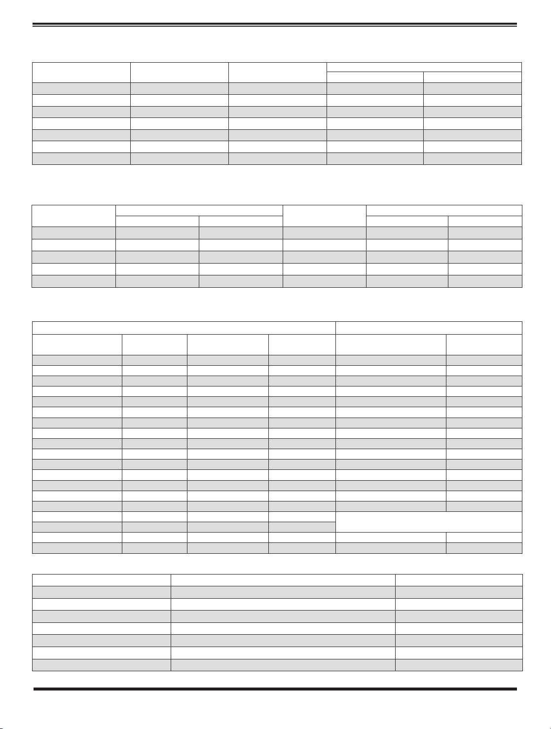
Repair Kits for 100-04/100-23 Hy-Check Main Valves
For: Hy-Check Main Valves—150 Pressure Class Only
Includes: Diaphragm, Disc and O-Rings and full set of spare Spacer Washers.
Larger Sizes: Consult Factory.
Repair Kits for 100-02/100-21 Powertrol and 100-03/100-22 Powercheck Main Valves
For: Powertrol and Powercheck Main Valves—150 Pressure Class Only
Includes: Diaphragm, Disc (or Disc Assembly) and O-rings and full set of spare Spacer Washers.
Repair Kits for Pilot Control Valves (In Standard Materials Only)
Includes: Diaphragm, Disc (or Disc Assembly), O-Rings, Gaskets or spare Screws as appropriate.
Repair Assemblies (In Standard Materials Only)
CLA-VAL
Copyright Cla-Val 2018 Printed in USA Specifications subject to change without notice.
1701 Placentia Ave • Costa Mesa CA 92627 Phone: 949-722-4800 • Fax: 949-548-5441 • E-mail: info@cla-val.com • www.cla-val.com
©
N-RK (R-08/2018)
Valve
Size
Kit Stock Number
100-02
Valve
Size
Kit Stock Number
100-02 & 100-03 100-21 & 100-22
3
⁄8”
9169901H
2
1
⁄2”
9169910J N/A
1
⁄2” & 3⁄4”
9169902F
3”
9169911G 9169905J
1” 9169903D
4”
9169912E 9169911G
1
1
⁄4” & 11⁄2”
9169904B
6”
9169913C 9169912E
2” 9169905J
8”
99116G 9169913C
10”
9169939H 99116G
12”
9169937B 9169939H
Valve
Size
Kit Stock Number
Valve
Size
Kit Stock Number
100-04 100-23 100-04 100-23
4” 20210901B N/A 12” 20210905H 20210904J
6” 20210902A 20210901B 14” 20210906G N/A
8” 20210903K 20210902A 16” 20210907F 20210905H
10” 20210904J 20210903K 20” N/A 20210907F
24” N/A 20210907F
BUNA-N
®
(Standard Material) VITON (For KB Controls)
Pilot
Control
Kit Stock
Number
Pilot
Control
Kit Stock
Number
Pilot
Control
Kit Stock
Number
CDB 9170006C CFM-9 12223E CDB-KB 9170012A
CDB-30 9170023H
CRA (w/bucking spring)
9170001D CRA-KB N/A
CDB-31 9170024F
CRD (w/bucking spring)
9170002B
CRD-KB (w/bucking spring)
9170008J
CDB-7 9170017K
CRD (no bucking spring)
9170003K CRL-KB 9170013J
CDH-2 18225D CRD-18 20275401K CDHS-2BKB 9170010E
CDHS-2 44607A CRD-22 98923G CDHS-2FKB 9170011C
CDHS-2B 9170004H CRL (55F, 55L) 9170007A CDHS-18KB (no bucking spring) 9170009G
CDHS-2F 9170005E CRL60/55L-60 9170033G
102C-KB
1726202D
CDHS-3C-A2 24657K CRL60/55L60 1" 9170042H
CDHS-8A 2666901A CRL-4A 43413E
CDHS-18 9170003K CRL-5 (55B) 65755B
CDS-4 9170014G CRL-5A (55G) 20666E
CDS-5 14200A CRL-18 20309801C
CDS-6 20119301A Universal CRL 9170041K
CDS-6A 20349401C CV 9170019F
CFCM-M1 1222301C X105L (O-ring) 00951E
Buna-N
®
CFM-2 12223E 102B-1 1502201F
CFM-7 1263901K 102C-2 1726201F CRD Disc Ret. (Solid) C5256H
CFM-7A 1263901K 102C-3 1726201F CRD Disc Ret. (Spring) C5255K
Control Description Stock Number
CF1-C1 Pilot Assembly Only 89541H
CF1-Cl Complete Float Control less Ball and Rod 89016A
CFC2-C1 Disc, Distributor and Seals 2674701E
CSM 11-A2-2 Mechanical Parts Assembly 97544B
CSM 11-A2-2 Pilot Assembly Only 18053K
33A 1” Complete Internal Assembly and Seal 2036030B
33A 2” Complete Internal Assembly and Seal 2040830J
When ordering, please give complete nameplate data of the valve and/or control being repaired. MINIMUM ORDER CHARGE APPLIES
Larger Sizes: Consult Factory.
 Loading...