

Page 1

INSTALLATION / OPERATION / MAINTENANCE
DESCRIPTION
This manual contains information for installation, operation and maintenance of the Cla-Val 100-03 Powercheck, an automatic valve
designed for use where independent operating pressure is desired,or
when line fluid is unsuitable as an operating medium.
This valve is a hydraulically operated, diaphragm type, globe or angle
pattern valve. It is single seated and incorporates into its design two
operating chambers sealed from one another by a flexible synthetic
rubber diaphragm. Pressure applied to the upper chamber closes the
valve; when applied to the lower chamber, it opens the valve.
With proper pilot controls, the valve can be held in any intermediate
position between fully open and tightly closed unless a static condition
or pressure reversal occurs, in which case the valve closes to prevent
return flow regardless of the diaphragm position.
INSTALLATION
Allow sufficient room around the valve assembly to make adjustments
and for disassembly.
NOTE: BEFORE THE VALVE IS INSTALLED, PIPE LINES SHOULD
BE FLUSHED OF ALL CHIPS, SCALE AND FOREIGN MATTER.
MODEL
100-03
Powercheck Valve
TROUBLE SHOOTING
It is recommended that gate or block valves be installed on both the
upstream and downstream sides of the 100-03 to facilitate isolating
the valve for preventative maintenance.
Place the valve in the line with flow through the valve in the direction
indicated on the inlet name plate or by flow arrows and with the cover
"UP" Other positions are not acceptable due to the check feature.
When a pilot control system is installed on the Powercheck Valve, use
care to prevent damage. If it is necessary to remove fittings or components, be sure they are kept clean and replaced in the exact order
of removal.
After the valve is installed and the system is first pressurized, vent air
from the cover chamber and tubing by loosening fittings at all high
points.
Principle of Operation
→
Four - Way Control
→
Four - Way Control
The following trouble shooting information deals strictly with
the Powercheck Valve; however some "possible causes" will
refer to components that may exist in the variety of control
systems available for the valve. All trouble shooting is possible without removing the valve from the line.
SERVICE SUGGESTIONS
(Service Suggestions Chart)
CAUTION: Extreme care should be taken when servicing the
valve. Gate or line block valves must be closed upstream and
downstream of the valve before starting disassembly. When
there are no block or gate valves to isolate the Powercheck
Valve it should be realized that the valve cannot be serviced
under pressure. Steps must be taken to remedy this situation
before proceeding.
→
Four - Way Control
When operating pressure below the
Full Open Operation
diaphragm is applied and pressure is
relieved from the cover chamber, the
valve is held open allowing full flow.
Note: For optimum operation of built-in check feature, installation with stem vertically up is recommended.
Tight Closing Operation
When pressure below the diaphragm is
relieved and operating pressure is
applied to the cover chamber, the valve
closes drip-tight.
Check Action
When a static condition or pressure
sal occurs, the split stem design allows the
valve to instantly check closed. Return flow
is prevented regardless of the diaphragm's
position.
rever-
Page 2
SERVICE SUGGESTIONS
SYMPTOM
Valve fails
to close.
Valve fails
to open.
Valve closes but
leakage occurs.
O-Ring
failure.
POSSIBLE
CAUSE
Stem stuck in open
position.
Worn diaphragm or
loose upper stem
nut.
Foreign object on
valve seat.
Pressure not being
released from
power unit chamber.
Operating pressure
not getting into
valve cover.
Insufficient line
pressure.
Stem stuck in
Closed or semiopen
position.
Worn diaphragm or
loose upper stem
nut.
Foreign object on
top of disc retainer.
Pressure not being
released from cover
chamber.
Operating pressure
not applied into
power unit chamber.
Worn disc or seat.
Mineral deposits on
stem cause abrasion on O-ring.
TEST
PROCEDURE
Vent power unit
chamber. Apply
pressure to cover
chamber. Valve
should close.
Apply pressure in
power unit chamber
and vent cover.
Continuous flow
from cover indicates
this trouble.
Valve opens okay,
but only closes part
way.
Make sure pressure
is being released by
opening a fitting
into the chamber. It
valve then closes,
refer to remedy.
Use pressure
gauge or loosen
cover plug to check
for pressure.
Check line pressure.
Vent cover. Apply
pressure to power
unit chamber.
Apply pressure in
power unit chamber
and vent cover.
Continuous flow
from cover indicates
this problem.
Valve closed okay
but won't open all
the way.
Open a fitting or
remove a plug from
cover chamber. It
cover chamber
vents and valve
opens, see remedy.
Loosen a fitting in
this chamber to
check for pressure
at this point.
The best procedure
here is to disassemble the valve
and inspect these
parts.
Remove pressure
from both cover and
power unit chambers and apply line
pressure to valve.
Open line from
power unit chamber
and observe continuos flow.
REMEDY
Disassemble,exami
ne all internal parts
for cause of the
sticking condition
and clean off scale
deposits.
Disassemble and
replace diaphragm
or tighten the valve
stem nut.
Try operating valve
a few times. This
might dislodge the
object. If this fails,
disassemble and
remove the obstruction.
Check control system. Tube line or
nipple might be
plugged up.
Clean tubing or
pipe fittings into
cover chamber.
Open CK2
Valve
Establish line pressure.
Disassemble,
examine all internal
parts for cause of
the sticking problem, and clean off
scale deposits.
Disassemble and
replace diaphragm
or tighten valve
stem nut.
Try operating valve
a few times. This
might dislodge the
object It this tails,
disassemble and
remove the obstruction.
Check control system. Check lines or
pipe fittings. Clean
out any plugged
lines.
Clean tubing or
pipe fittings into
power unit chamber.
Replace worn parts.
Disassemble and
replace O-ring.
Isolation
in control lines.
FREEDOM OF MOVEMENT
The following procedures can be used to determine if the
valve opens and closes fully. During this test the diaphragm
can be checked for damage.
The Powercheck Valve will have a control to open and close
the valve. Position the control so that pressure is applied to
the cover chamber (above the valve diaphragm). This will
close the Powercheck Valve. Check the drain from the control
that discharges to atmosphere.
Once the liquid from the lower diaphragm chamber is drained
the discharge should stop. If the discharge continues after the
normal time it takes to drain then the diaphragm is damaged,
or the stem nut is loose, or the stem o~ring is leaking If the
discharge is continuous from both chambers then there is a
possibility that the diaphragm or the pilot control is damaged.
If the valve is equipped with a "Dry Drain" (control drain piped
to downstream end of the valve) then same procedure is followed except the CK2 Shutoff Cock on the downstream end
of the valve must be closed and the drain line disconnected
and drained to atmosphere. It can then be checked as above.
Measurement of the vertical travel of the stem (diaphragm
assembly) will make it possible to determine if the travel, or
stroke is restricted. The following chart provides this measurement. It is necessary to have either the X101 Valve
Position Indicator or X105 Limit Switch Assembly installed on
the valve to visually check the travel.
Mark the position of the stem on the X101 or X105 when the
valve is closed. Reposition the control so that pressure is apt
plied below the diaphragm and the cover chamber is drained.
Determine the extent of the stem travel. Check this movement with the stem travel chart. If the stroke is different than
listed (5% to 10%) then there is good reason to believe something is mechanically restricting the stroke of the valve at one
end of its travel. If it is determined that f low does not stop
through the valve when in the indicated "closed" position, the
obstruction probably is between the disc and the seat, or in
the power unit chamber below the diaphragm. If the flow
stops, the obstruct tion is likely in the cover chamber above
the diaphragm or possibly above the disc retainer. Refer to
the sectional view under Principle of Operation.
If operation of the valve a few times does not dislodge the foreign object obstructing the diaphragm assembly (stem)
movement then the valve must be disassembled and the
problem located and corrected. See disassembly instructions.
STEM TRAVEL
(fully open tp fully closed)
VALVE SIZE
INCHES
1
1 1/4
1 1/2
2
2 1/2
3
4
6
8
10
12
14
16
MM
25
32
40
50
65
80
100
150
200
250
300
350
400
TRAVEL
INCHES
0.3
0.4
0.4
0.6
0.7
0.8
1.1
1.7
2.3
2.8
3.4
3.9
4.5
MM
8
10
10
15
18
20
23
43
58
71
86
99
114
Page 3

MAINTENANCE
Preventative Maintenance
The Cla Val Powercheck Valves require no lubrication or packing and a minimum of maintenance. However. a periodic
inspection schedule should be established to determine how
the fluid velocity as well as the substances occurring in natural
waters are effecting the valve. These substances can be dissolved minerals, colloidal and suspended particles. Effect of
these actions or substances must be determined by inspection.
DISASSEMBLY
First mark the side of the valve cover, power unit body an valve
body so that reassembly of these parts will be exact) as
removed.
The Powercheck Valve inspection or maintenance can be
accomplished without removal of the valve body from the line.
Shut off pressure to the valve, both inlet, outlet and independent operating pressure when used.
WARNING: Maintenance personnel can be injured and equip
ment and property damaged if disassembly is attempted with
pressure in the system.
After pressure has been released from the valve control system
and operating chambers of the valve, remove the controls and
tubing. Obtain a schematic of the assembly or note and sketch
position of tubing and controls for reassembly. Replacing tubing
into the control ports exactly as removed is necessary. Failure
to reassemble properly will cause the valve to malfunction and
possibly cause serious damage.
CAUTION: During service performed on the stem assembly.
the stem surfaces must not be damaged. If a vice or other holding device is used to grip the stem. soft jaws of brass or copper
must be used to protect the precision ground surface of the
stainless steel stem. If the stem is marred no amount of careful
dressing can restore the stem to its original condition.
Inspect the threads on the stem. Mineral deposits that prevent
the nuts from turning must be cleaned from the threads.
A 5% solution of muriatic acid will soften mineral or scale
deposits to assist in removal of nuts and the general cleaning
of parts. Flush the parts thoroughly with water immediately after
cleaning. Care must always be exercised when handling acid.
Read the warning label on the acid container to be sure of correct method of use and disposal after use.
Hold the stem in a vice with soft jaws (see above) when removing the stem nut. Slide off the assembly leaving a completely
disassembled upper stem assembly. Remove the disc and disc
retainer from the lower stem. Refer to the sectional view of the
valve size being serviced. This will assist in the disassembly
procedure outlined above. Reassembly instructions outline
proper procedure and quantity of spacer washers. This is especially important if the disc is replaced.
Check the upper and lower stems for scale and freedom of
movement. Insert the lower stem into the stem (upper). The
insertion fully of these parts must be free from binding or resistance. Clean and polish the telescoping parts. Restricted movement of these parts could cause the check feature to fail to
function.
Remove cover nuts and cover. If the valve has been in service
for any length of time' chances are the cover will have to be
loosened by driving upward along the edge of the cover with a
dull cold chisel. See Figure 1.
Valve Cover
Dull Cold Chisel
(Angle upward as
much as possible)
Hammer
FIGURE 1.
NOTE:
When block and tackle or a power hoist is to be used to lift the
valve cover insert a proper size eye bolt in place of the center
cover plug. Pull cover straight up to keep from damaging the
power unit stem bearing and upper stem.
Power unit body can now be lifted from the valve body. The
stem with diaphragm will be removed with the power unit body.
The disc retainer assembly with lower stem will separate
(check feature) from the upper stem and power unit body.
Inspection Of Parts
Returning to the valve body in the line. the seat should now b
inspected for damage. If the seat requires removal use the following tools. Seats in valve sizes1/2" and 3/4" can be remove
with a hex socket wrench. Seats in valve sizes 1" through 6"
should be removed with accessory X-109 Seat Removing Too
available from the factory. Seats in valve sizes 8" through 16"
may be removed with a screw driver. If upon removal of the
screws the seat cannot be lifted out, it will be necessary to use
a hard rubber mallet and tap the seat loose.
Any buildup of mineral or scale should be cleaned from the
valve body at this time. Inspection of the cover and power unit
body surfaces that contact the diaphragm is important. Clean
and smooth. with wet or dry emery paper. any roughness that
could damage the diaphragm. Inspect and recondition the surface on the upper and lower diaphragm washers The perimeter
if the diaphragm washers is the most likely area to cause
diaphragm wear if the surface is not smooth. Take extra care to
make this a smooth finish
Inspect the power unit body bearing insert O-ring that is in contact with the stem If it is worn. nicked or cut. replace it.
The cover bearing should also be checked for excessive wear,
using the upper end of the stem to check for excessive lateral
movement. A special tool for each size valve is available from
the factory to remove the cover bearing. Cover bearing replacement is seldom necessary.
Inspect the diaphragm for cracks or chafing. Replace the
diaphragm if damaged
Inspect the disc and replace if the surface is damaged or worn
If a new disc is not available. the existing disc can be turned
over, exposing the unused surface for contact with the seat.
The disc guide should be checked and cleaned of scales and
mineral deposits. Due to the close tolerance between the outer
periphery of the disc guide and the inner area of the valve seat,
no scale or mineral deposits should be overlooked.
Page 4

REASSEMBLY
To reassemble, reverse the order of disassembly
If the disc has been removed, it is important that correct
pressure be on the disc from the disc guide when the
lower stem nut is tight. Use sufficient spacer washers to
obtain slight pressure (by visual indention) on the disc.
Indention should be slight. Refer to seat and disc detail
drawings for location of spacer washers for various valve
sizes.
NOTE: New discs will usually require a different number
of spacer washers to obtain the right amount of "grip" on
the disc.
Place the lower stem assembly onto the seat with the
disc in contact with the valve seat. If a large spring (4",
6", 8" only) was removed upon disassembly, replace on
top of the disc retainer.
The power unit body with gasket, (body to power unit) or
O-ring, can be installed on the body. Be sure the power
unit section is replaced exactly in the same position as
removed. The end of the lower stem will be visible in the
center of the power unit bearing. Care must be taken so
the power unit bearing or lower stem is not damaged
during this assembly. A hoist may be necessary for larger valve sizes.
NOTE: Valves 4" thru 16" use an O-ring body to power
unit seal. During placement onto the body apply a light
weight grease into the power unit groove to hold the Oring in place when installing on the body.
Install on the upper stem the lower diaphragm washer,
the diaphragm, the upper diaphragm washer, then screw
the stem nut and tighten securely so the upper and lower
diaphragm washer cannot be turned on the stem. During
the tightening of the upper stem nut, the stem should be
held in a vice with soft brass jaws. The upper stem and
diaphragm assembly can now be lowered into the power
unit bearing, the hollow end of the stem sliding on to the
end of the lower stem. Move the upper stem and
diaphragm assembly up and down to check freedom of
movement of the lower and upper stem.
CAUTION: Do not lubricate or grease the hollow end of
upper stem or upper end of the lower stem. This could
cause the check feature to become inoperative.
Replace cover chamber spring on the upper diaphragm
washer.
NOTE: Some valves may not have a cover chamber
spring.
Place the cover on the power unit body aligning the
index marks. Secure the cover with 8 stud nuts Tighten
the nuts firmly with a cross-over pattern until all nuts are
tight:
NOTE: Valve sizes 1" thru 3" are bolted with 8 nuts
(power unit body to valve body) and 8 nuts (cover to
power unit body). Tighten stud nuts firmly with crossover pattern until all nuts are tight.
When the stem is removed from the valve a tool can be
fabricated to check for unrestricted stem movement after
reassembly, and also check for correct stem travel.
Valves size 1 1/4" thru 24/2" are threaded 10-32 UNF
(internal threads) on the top of the stem. Valve sizes 3"
and 4" are threaded ,1/4 -28 UNF. Valve sizes 6" thru 14"
are threaded 34-24 UNF. The 16" valves are threaded,1/2-20 UNF.
A length of rod threaded on one end can be threaded
into the stem through the plug hole in the center of the
cover. It is possible with this rod to move the diaphragm
assembly up from the seat freely, returning to the seat by
its own weight. Larger valve sizes may require a tee
handle to assist lifting heavier assemblies. The stroke of
the stem should correspond closely with the chart.
Reinstall the control system and tubing exactly as it was
before disassembly.
The Powercheck Valve can be tested for tight closure as
well as the tightness of the seal across the diaphragm.
inlet line pressure, or independent operating pressure
can also be used to check the freeness and travel of the
diaphragm assembly. Refer to the operation paragraph
and principle of operation sectional views for opening
and closing operation.
The downstream or outlet shutoff valve remains closed.
If the control system has a pilot or control that can position the valve to a closed position, put the control in a
position to close the Powercheck. Lacking a control, inlet
pressure must be connected to the cover of the
Powercheck Valve.
Open upstream gate or line block valve just enough to
allow flow.
Have the power unit body, center section, open to
atmosphere. The power unit body will be atmospheric if
the control is being used.
Partially disconnect a fitting on the discharge side of the
valve. Do not remove fully unless there is no pressure.
After the valve is in the closed position for a few minutes,
all draining of the power unit body should stop. This will
indicate a good seal across the valve seat and the
diaphragm.
USEFUL INFORMATION OR HINTS
1.The approximate volume of liquid discharged from the
chamber above the diaphragm when the valve moves
from the fully closed position to fully open is as follows:
VALVE SIZE
1/2"
3/4"
1"
1 1/4"
1 1/2"
2"
2 1/2"
3"
4"
6"
8"
10"
12"
14"
16"
DISPLACEMENT
0.340 Fl. Oz.
0.340 Fl. Oz.
0.700 Fl. Oz.
0.020 Gal.
0.020 Gal.
0.032 Gal.
0.043 Gal.
0.080 Gal.
0 169 Gal
0.531 Gal.
1.260 Gal.
2.510 Gal.
4.000 Gal.
6.500 Gal.
9.570 Gal.
.01 Liters
.01 Liters
.02 Liters
.10 Liters
.10 Liters
.10 Liters
.20 Liters
.30 Liters
.60 Liters
2.00 Liters
4.75 Liters
9.50 Liters
15.14 Liters
24.60 Liters
36.20 Liters
Page 5
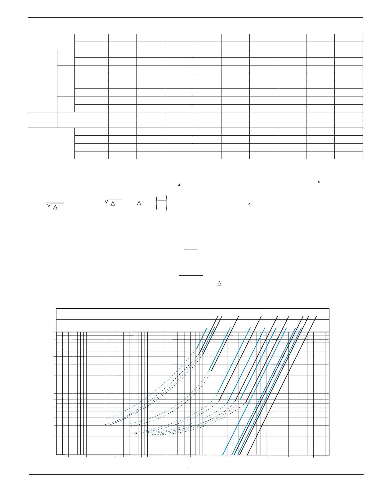
Functional Data
Valve Size
C
V
Factor
Equivalent
Length
of
Pipe
K
Factor
Liquid Displaced from
Cover Chamber When
Valve Opens
*Estimated
C
Factor
V
Formulas for computing C Factor, Flow (Q) and Pressure Drop
Q
=
C
V
K Factor (Resistance Coefficient)
The Value of K is calculated from the formula:
(U.S. system units)
Equivalent Length of Pipe
Equivalent lengths of pipe (L) are determined from the formula:
(U.S. system units)
Fluid Velocity
Fluid velocity can be calculated from the following formula:
(U.S. system units)
Inches 21⁄2 3 4 6 8 10 12 14 16
Globe
Pattern
Angle
Pattern
Globe
Pattern
Angle
Pattern
Globe Pattern
Angle Pattern
mm.
Gal./Min. (gpm.)
Litres/Sec. (l/s.)
Gal./Min. (gpm.)
Litres/Sec. (l/s.)
Feet (ft.)
Meters (m.)
Feet (ft.)
Meters (m.)
Fl. Oz
U.S. Gal.
ml
Litres
65 80 100 150 200 250 300 350 400
85 115 200 440 770 1245 1725 2300 2940
20 28 48 106 185 299 414 552 706
101 139 240 541 990 1575 2500* 3060* 4200*
24 33 58 130 238 378 600 734 1008
53 85 116 211 291 347 467 422 503
16 26 35 64 89 106 142 129 154
37 58 80 139 176 217 222* 238* 247*
12 18 25 43 54 66 68 73 75
4.6 6.0 5.9 6.2 6.1 5.8 6.1 5.0 5.2
3.3 4.1 4.1 4.1 3.7 3.6 2.9 2.8 2.6
— — — — — — — — —
.04 .08 .17 .53 1.26 2.51 4.0 6.5 9.6
163 303 643 — — — — — —
— — — 2.0 4.8 9.5 15.1 24.6 36.2
V
2
Q
K =
P
=
894d
C
v
C
V
4
2
=
C
P
Q
P
V
V =
( P):
L =
.4085 Q
d
K
12 f
2
d
Model 100-03
Where:
C
=
U.S. (gpm) @ 1 psi differential at 60 F water
V
(l/s) @ 1 bar (14.5 PSIG) differential
=
at 15 C water
=
inside pipe diameter of Schedule 40 Steel Pipe (inches)
d
friction factor for clean, new Schedule 40 pipe
=
f
(dimensionless) (from Cameron Hydraulic Data,
18th Edition, P 3-119)
Resistance Coefficient (calculated)
=
K
=
Equivalent Length of Pipe (feet)
L
=
Flow Rate in U.S. (gpm) or (l/s)
Q
=
Fluid Velocity (feet per second) or (meters per second)
V
=
Pressure Drop in (psi) or (bar)
P
or
Model 100-03 Flow Chart (Based on normal flow through a wide open valve)
2
Angle Valve Sizes (Inches)
Globe Valve Sizes (Inches)
100
80
60
40
30
psi
20
10
8
Pressure Drop —
6
4
3
2
1
53
10 20 30 40 60 80 100 200 500 1000 2000 5000 10,000 20,000 50,000
Flow Rate gpm (water)
1/2
34
21/2
3
6
1046
8
810
14
12
16
14
12
16
Page 6

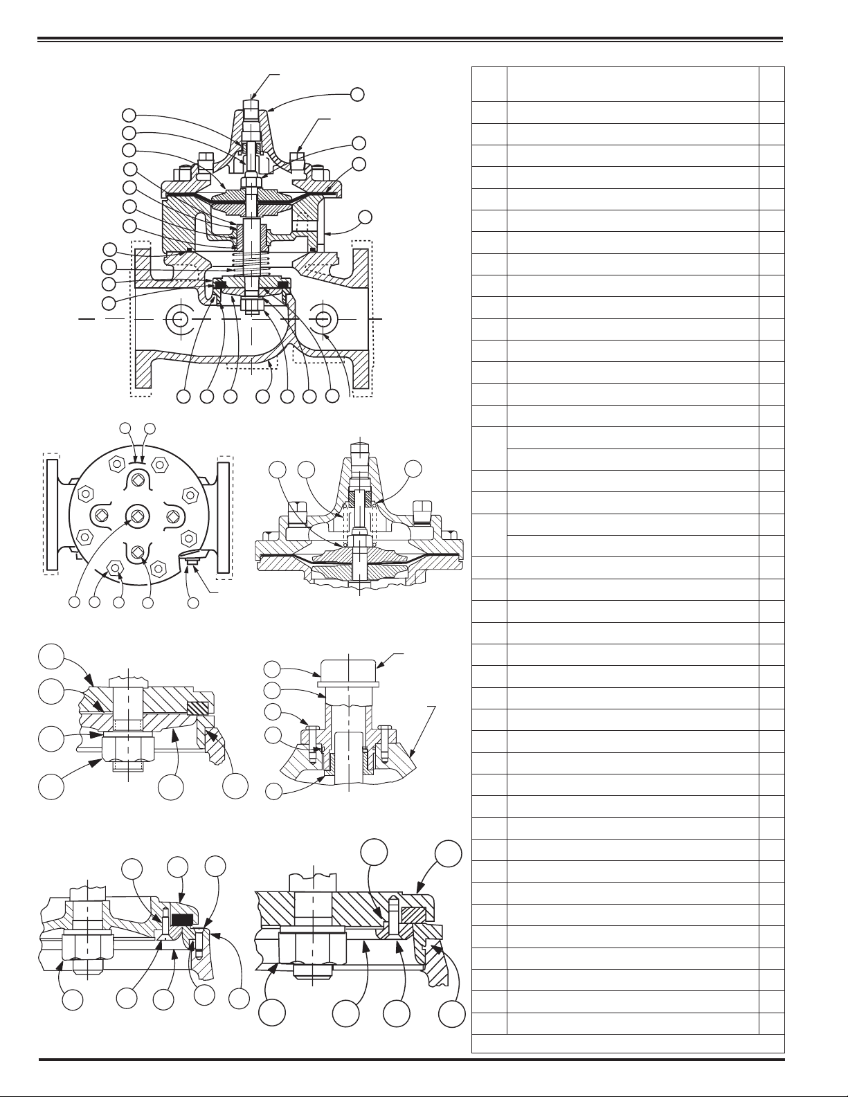
100-03 Powercheck Valve 1” - 3” Sizes
30
37
39
31
25
22
32
21
19
34
19
10
1 3 2
19
14
38
Cover View
36
24
J
NPT
7
Model 100-03KH
1” - 3”
Seat & Disc Details
33
16
35
15
20
ITEM
NO.
1 Center Cover Plug 1
2 Cover Plug
Hex Nut (4”-16” only) A/R
3
4 Cover Bearing 1
5 Cover 1
6 Pipe Cap (16” only) 1
7 Body Plug
8 Hex Bolt (16” only) 8
O-Ring (16” only) 1
9*
Gasket (1” - 3” only) 1
10*
11 Upper Stem Nut 1
12 Diaphragm Washer 2
Diaphragm 1
13*
14 Nameplate 1
Stem O-Ring 1
15*
Bearing Retainer (1” -3” only) 1
16
Bearing Ring Retainer (4” - 16” only) 1
17 Powerunit Body 1
Bearing O-Ring (4” - 16” only) 1
18*
Hex Bolt (1” - 3” only)
19
Stud (4” - 16” only)
20 Powerunit Body 1
21 Lower Stem Nut 1
22 Spacer Washer
23 Screw, Flat Hd (6” - 16” Only)
24 Disc Guide 1
25 Disc Retainer 1
Disc 1
26*
27 Upper Stem 1
28 Screw, Flat Hd (8” - 16” only)
29 Seat 1
30 Body 1
31 Spring (100PCKH / 100CAKH only) 1
32 Lockwasher 1
Seat O-Ring 1
33*
Gasket, Bearing (1” - 3” only) 1
34*
35 Screw FIL. Hd (1”-2 1/2” Bolt HX Hd (3”) 4
36 Upper Spring Washer (100PCKCH / 100PCAKCH) 1
37 Lower Spring Washer (100PCKCH / 100PCAKCH) 1
38 Drive Screw 2
39 Lower Spring (1” - 10” only) 1
40 Lower Stem 1
41 Cover Bearing Housing (16” only) 1
PART DESCRIPTION Qty
*Recommended Spare Parts
A/R
A/R
A/R
A/R
A/R
A/R
A/R
Page 7
G
4
J
27
12
17
16
18
15
10
39
25
26
INLET
29
33
14
38
1 3 2
19
7
Cover View
25
22
32
21
1”-4” Sizes (Seat and Disc Detail)
21
8”-16” Sizes (Seat and Disc Detail)
22
23
24
24
25
28
33
24
J
100-03 Powercheck Valve 4” - 16” Sizes
NPT
5
K
NPT
11
13
20
OUTLET
21
30
NPT
33
29
32
22
H
NPT
37
31
36
1 1/4” - 4” Sizes (No-Core Cover)
6
41
8
9
4
NPT
COVER
16” Cover Bearing Housing Detail
22
21
6” Sizes (Seat and Disc Detail)
24
23
25
33
ITEM
NO.
1 Center Cover Plug 1
2 Cover Plug A/R
3 Hex Nut (4”-16” only) A/R
4 Cover Bearing 1
5 Cover 1
6 Pipe Cap (16” only) 1
7 Body Plug A/R
8 Hex Bolt (16” only) 8
9* O-Ring (16” only) 1
10* Gasket (1” - 3” only) 1
11 Upper Stem Nut 1
12 Diaphragm Washer 2
13* Diaphragm 1
14 Nameplate 1
15* Stem O-Ring 1
Bearing Retainer (1” -3” only) 1
16
Bearing Ring Retainer (4” - 16” only) 1
17 Powerunit Body 1
18* Bearing O-Ring (4” - 16” only) 1
Hex Bolt (1” - 3” only) A/R
19
Stud (4” - 16” only) A/R
20 Powerunit Body 1
21 Lower Stem Nut 1
22 Spacer Washer A/R
23 Screw, Flat Hd (6” - 16” Only) A/R
24 Disc Guide 1
25 Disc Retainer 1
26* Disc 1
27 Upper Stem 1
28 Screw, Flat Hd (8” - 16” only) A/R
29 Seat 1
30 Body 1
31 Spring (100PCKH / 100CAKH only) 1
32 Lockwasher 1
33* Seat O-Ring 1
34* Gasket, Bearing (1” - 3” only) 1
35 Screw FIL. Hd (1”-2 1/2” Bolt HX Hd (3”) 4
36 Upper Spring Washer (100PCKCH / 100PCAKCH) 1
37 Lower Spring Washer (100PCKCH / 100PCAKCH) 1
38 Drive Screw 2
39 Lower Spring (1” - 10” only) 1
40 Lower Stem 1
41 Cover Bearing Housing (16” only) 1
PART DESCRIPTION Qty
*Recommended Spare Parts
Page 8
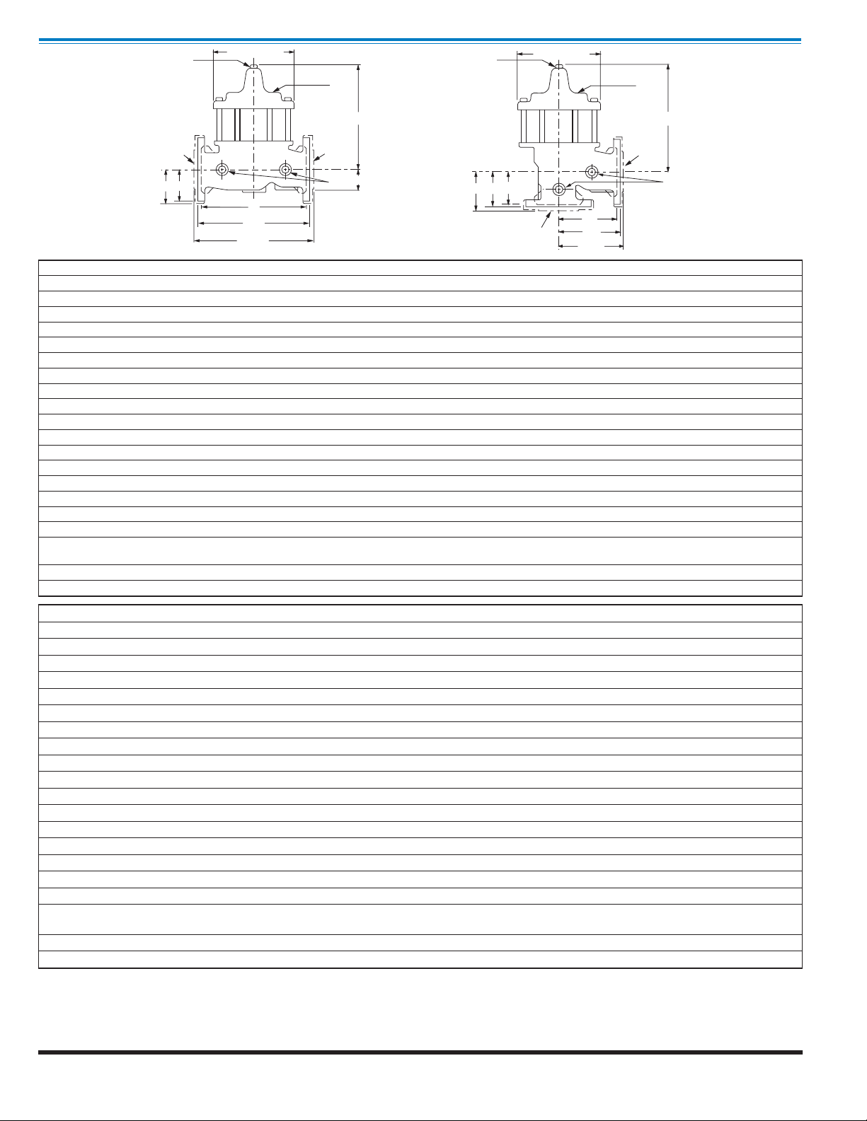
Dimensions
CLA-VAL
Copyright Cla-Val 2009 Printed in USA Specifications subject to change without notice.
P.O. Box 1325 • Newport Beach, CA 92659-0325 • Phone: 949-722-4800 • Fax: 949-548-5441 • E-mail: claval@cla-val.com • Website cla-val.com
©
J
B (DIAMETER)
J
K
B (DIAMETER)
Model 100-03
K
OUTLET
C
H
100-03 (Angle)
100-03 (Globe)
INLET
FF
C
OUTLET
E
F
A
AA
AAA
H
GGG
GG G
INLET
D
DD
DDD
Valve Size (Inches) 2 1⁄2 3 4 6 8 10 12 14 16
A Threaded
AA 150 ANSI
AAA 300 ANSI
B Dia.
C Max.
D Threaded
DD 150 ANSI
DDD 300 ANSI
E
F 150 ANSI
FF 300 ANSI
G Threaded
GG 150 ANSI
GGG 300 ANSI
H NPT Body Tapping
J NPT Cover Center Plug
K NPT Cover Tapping
Valve Stem Internal
Thread UNF
Stem Travel
Approx. Ship Wt. Lbs.
11.00 12.50 — — — — — — —
11.00 12.00 15.00 20.00 25.38 29.75 34.00 39.00 41.38
11.62 13.25 15.62 21.00 26.38 31.12 35.50 40.50 43.50
8.00 9.12 11.50 15.75 20.00 23.62 28.00 32.75 35.50
10.31 11.19 14.25 18.44 21.81 23.38 29.31 32.12 35.00
5.50 6.25 — — — — — — —
5.50 6.00 7.50 10.00 12.69 14.88 17.00 19.50 20.69
5.81 6.63 7.81 10.50 13.19 15.56 17.75 20.25 21.75
1.69 2.06 3.19 4.31 5.31 9.25 10.75 12.62 15.50
3.50 3.75 4.50 5.50 6.75 8.00 9.50 10.50 11.75
3.75 4.13 5.00 6.25 7.50 8.75 10.25 11.50 12.75
4.00 4.50 — — — — — — —
4.00 4.00 5.00 6.00 8.00 8.62 13.75 14.88 15.69
4.31 4.38 5.31 6.50 8.50 9.31 14.50 15.62 16.50
1
⁄2
1
⁄2
1
⁄2
10-32
1
1
1
1
⁄4-28
1
⁄4-28
3
⁄4
3
⁄4
3
⁄4
⁄2
⁄2
⁄2
3
⁄8-24
3
⁄4
3
⁄4
3
⁄4
1 1 1 1 1
1 1
1
1
⁄4 11⁄2
1 1 1 1 1
3
⁄8-24
3
⁄8-24
3
⁄8-24
3
⁄8-24
1
⁄2-20
0.7 0.8 1.1 1.7 2.3 2.8 3.4 4.0 4.5
65 95 190 320 650 940 1675 2460 3100
2
Valve Size (mm) 65 80 100 150 200 250 300 350 400
A Threaded
AA 150 ANSI
AAA 300 ANSI
B Dia.
C Max.
D Threaded
DD 150 ANSI
DDD 300 ANSI
E
F 150 ANSI
FF 300 ANSI
G Threaded
GG 150 ANSI
GGG 300 ANSI
H NPT Body Tapping
J NPT Cover Center Plug
K NPT Cover Tapping
Valve Stem Internal
Thread UNF
Stem Travel
Approx. Ship Wt. Kgs.
279 318 — — — — — — —
279 305 381 508 645 756 864 991 1051
295 337 397 533 670 790 902 1029 1105
203 232 292 400 508 600 711 832 902
262 284 362 468 554 594 744 816 889
140 159 — — — — — — —
140 152 191 254 322 378 432 495 526
148 168 198 267 335 395 451 514 552
43 52 81 109 135 235 273 321 394
89 95 11 4 140 171 203 241 267 298
95 105 127 159 191 222 260 292 324
102 114 — — — — — — —
102 102 127 152 203 219 349 378 399
110 111 135 165 216 236 368 397 419
1
⁄2
1
⁄2
1
⁄2
10-32
1
1
1
1
⁄4-28
1
⁄4-28
3
⁄4
3
⁄4
3
⁄4
⁄2
⁄2
⁄2
3
⁄8-24
3
⁄4
3
⁄4
3
⁄4
1 1 1 1 1
1
1
1 1
⁄4 11⁄2
1 1 1 1 1
3
⁄8-24
3
⁄8-24
3
⁄8-24
3
⁄8-24
1
⁄2-20
18 20 28 43 58 71 86 102 11 4
30 43 86 145 295 426 760 1116 1406
2
Cla-Val Control Valves operate with maximum efficiency when mounted in horizontal piping with the main valve cover UP, however, other positions are acceptable. Due to component size and weight of 8 inch and larger valves, installation with cover UP is advisable. We recommend
isolation valves be installed on inlet and outlet for maintenance. Adequate space above and around the valve for service personnel should be
considered essential. A regular maintenance program should be established based on the specific application data. However, we recommend
a thorough inspection be done at least once a year. Consult factory for specific recommendations.
N-100-03 (R-1/09)
 Loading...