

Page 1

INSTALLATION / OPERATION / MAINTENANCE
MODEL
100-02
(Full Internal Port)
Powertrol Valve
DESCRIPTION
This manual contains information for installation, operation and maintenance of the Cla-Val Co. 100-02 Powertrol, an automatic valve
designed for use where independent operating pressure is desired,or
when line fluid is unsuitable as an operating medium.
This valve is a hydraulically operated, diaphragm type, globe or angle
pattern valve. it is single seated and incorporates into its design two
operating chambers sealed from one another by a flexible synthetic
rubber diaphragm. Pressure applied to the upper chamber closes the
valve; when applied to the lower chamber, it opens the valve.
With proper pilot controls, the valve can be held in any intermediate
position between fully open and tightly closed.
INSTALLATION
Allow sufficient room around the valve assembly to make adjustments
1.
and for disassembly.
NOTE: BEFORE THE VALVE IS INSTALLED, PIPE LINES
SHOULD BE FLUSHED OF ALL CHIPS, SCALE AND FOREIGN
MATTER.
TROUBLE SHOOTING
The following trouble shooting information deals strictly with the
Powertrol Valve; however some 'impossible causes" will refer to components that may exist in the variety of control systems available for the
valve. All trouble shooting is possible without removing the valve from
the line.
CAUTION: Extreme care should be taken when servicing the valve.
Gate or line block valves must be closed upstream and downstream of
the valve before starting disassembly. When there are no block or gate
valves to isolate the Powertrol Valve it should be realized that the valve
cannot be serviced under pressure. Steps must be taken to remedy this
situation before proceeding.
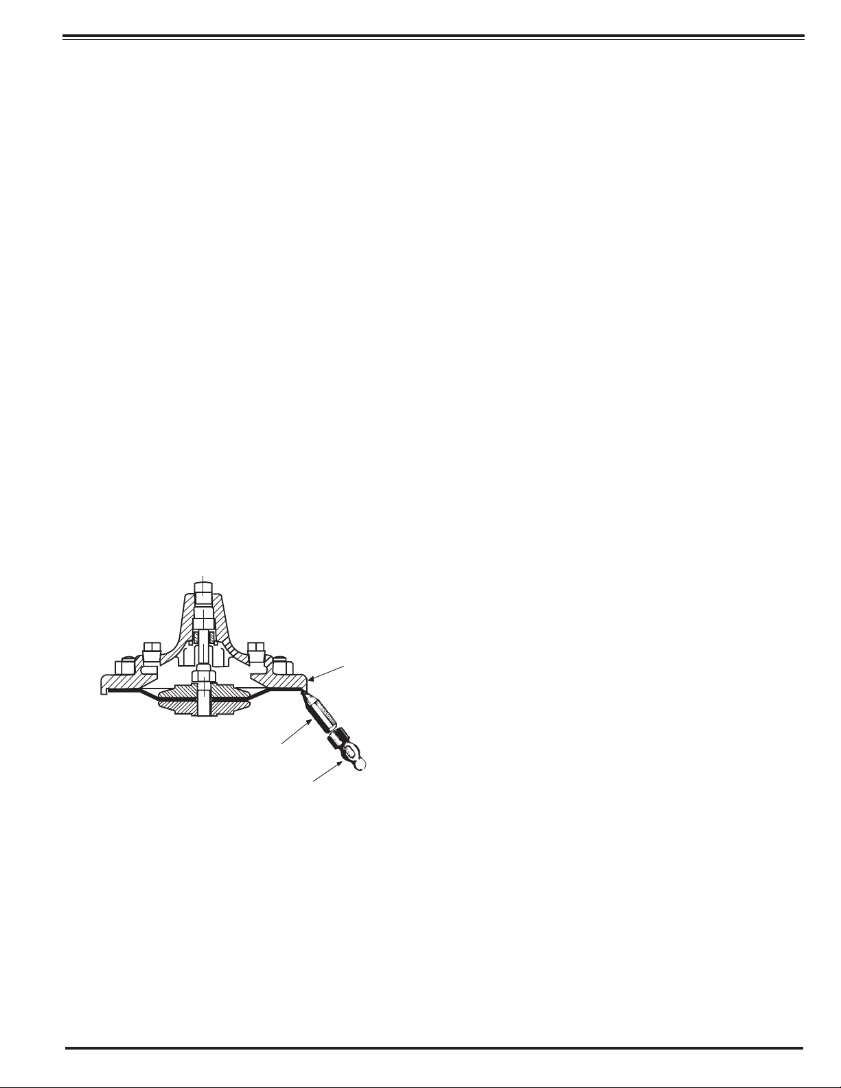
Principle of Operation
→
4 - Way Control
It is recommended that gate or block valves be installed on both the
2.
upstream and downstream sides of the 100-02 to facilitate isolating
the valve for preventative maintenance.
3.
Place the valve in the line with flow through the valve in the direction
indicated on the inlet name plate or by flow arrows.
Cla-Val Powertrol Valves operate with maximum efficiency when
4.
mounted in horizontal piping with cover "UP,' however, other positions
are acceptable. Due to the size and weight of the cover and internal
assembly of 4" and larger valves, installation with the cover "UP" is
advisable. This makes periodic inspection of internal parts readily
accessible.
5.
When a pilot control system is installed on the Powertrol Valve, use
care to prevent damage. If it is necessary to remove fittings or components, be sure they are kept clean and replaced in the exact order
of removal.
After the valve is installed and the system is first pressurized, vent air
6.
from the cover chamber and tubing by loosening fit" sings at all high
points.
→
4 - Way Control
→
4 - Way Control with lock
When operating pressure below the
Full Open Operation
diaphragm is applied and operating, pressure
is relieved from the cover chamber, the valve
is held open, allowing full flow.
When pressure below the diaphragm is
Tight Closing Operation
relieved and operating pressure is applied to
the cover chamber, the valve closes drip-tight.
Modulating Action
The valve holds any intermediate position
when operating pressure is equal above and
below the diaphragm. A Cla-Val four-way pilot
control with "lock" position can maintain this
balance by stopping flow in the pilot control
system.
Page 2

SYMPTOM
Valve fails to
close.
Valve fails to
open.
Valve closes but
leakage occurs.
O-Ring failure
*POSSIBLE
CAUSE
Stem stuck in open position.
Worn diaphragm
or loose upper
stem nut
Foreign object on
valve seat.
Pressure not being
released from power
unit chamber.
Operating
pressure not
getting into valve
cover.
Insufficient
line pressure.
Stem stuck in
closed or semiopen position.
Worn diaphragm
or loose upper
stem nut.
Foreign object on
top of disc retainer
Pressure not being
released from
cover chamber.
Operating pressure not
applied into power
unit chamber.
Worn disc or seat.
Mineral deposits
on stem cause
abrasion on ring.
TEST
PROCEDURE
Vent power unit chamber. Apply pressure to
cover chamber. Valve
should close.
Apply pressure in
power unit chamber
and vent cover.
Continuous flow from
cover indicates this
trouble.
Valve opens okay but
only closes part way.
Make sure
pressure is being
released by opening a
fitting into the chamber. If valve then closes refer to remedy.
Use pressure gauge
or loosen cover plug
to check for pressure.
Check line pressure.
Vent cover. Apply
pressure to power unit
chamber.
Apply pressure in
power unit chamber
and vent cover.
Continuous flow from
cover indicates this
pro bleary.
Valve closed okay
but won't open all
the way.
Open a fitting or
remove a plug from
cover chamber if
cover chamber vents
and valve opens, see
remedy.
Loosen a fitting in this
chamber to check for
pressure at this point.
The best procedure
here is to disassemble
the valve and inspect
these parts.
Remove pressure
from both cover and
power unit chambers
and apply line pressure to valve. Open
line from power unit
chamber and observe
continuos flow.
*Assuming control system is functioning properly.
REMEDY
Disassemble, examine
all internal parts for
cause of the sticking
condition and clean off
scale deposits.
Disassemble and
replace diaphragm or
tighten the valve stem
nut.
Try operating valve a
few times. This might
dislodge the object. If
this fails, disassemble
and remove the
obstruction.
Check control
system. Tube line or
nipple might be plugged
up.
Clean tubing or pipe fittings into cover chamber. Open CK2 Isolation
Valve in control lines.
Establish line pressure.
Disassemble, examine
all internal parts for
cause of the sticking
pro bleary, and clean off
scale deposits.
Disassemble and
replace diaphragm or
tighten valve stem nut.
Try operating valve a
few times. This might
dislodge the object. if
this fails disassemble
and remove the
obstruction.
Check control system.
Check lines or pipe fittings. Clean out any
plugged lines.
Clean tubing or pipe fittings into power unit
chamber.
Replace worn parts.
Disassemble and
replace O-ring.
FREEDOM OF MOVEMENT
The following procedures can be used to determine if the
valve opens and closes fully. During this test the diaphragm
can be checked for damage.
1.The Powertrol Valve will have a control to open and close
the valve. Position the control so that pressure is applied to
the cover chamber (above the valve diaphragm). This will
close the Powertrol Valve. Check the drain from the control
that discharges to atmosphere.
Once the liquid from the lower diaphragm chamber is drained
the discharge should stop. If the discharge continues after the
normal time it takes to drain then the diaphragm is damaged,
or the stem nut is loose, or the stem o-ring is leaking. If the
discharge is continuous from both chambers then there is a
possibility that the diaphragm or the pilot control is damaged.
If the valve is equipped with a "Dry Drain" (control drain piped
to downstream end of the valve) then same procedure is followed except the CK2 Shutoff Cock on the downstream end
of the valve must be closed and the drain line disconnected
and drained to atmosphere. It can then be checked as above.
Measurement of the vertical travel of the stem (diaphragm
assembly) will make it possible to determine if the travel, or
stroke is restricted. The following chart provides this measurement. It is necessary to have either the X101 Valve
Position Indicator or X105 Limit Switch Assembly installed on
the valve to visually check the travel.
Mark the position of the stem on the X101 or X105 when the
valve is closed. Reposition the control so that pressure is
applied below the diaphragm and the cover chamber is
drained. Determine the extent of the stem travel. Check this
movement with the stem travel chart. If the stroke is different
than listed (5% to 10%) then there is good reason to believe
something is mechanically restricting the stroke of the valve
at one end of its travel. If it is determined that flow does not
stop through the valve when in the indicated "closed" position,
the obstruction probably is between the disc and the seat, or
in the power unit chamber below the diaphragm. If the flow
stops, the obstruction is likely in the cover chamber above the
diaphragm or possibly above the disc retainer. Refer to the
sectional view under Principle of Operation.
If operation of the valve a few times does not dislodge the foreign object obstructing the diaphragm assembly (stem) movement then the valve must be disassembled and the problem
located and corrected. See disassembly instructions.
STEM TRAVEL
(Fully open to fully closed)
VALVE SIZE VALVE SIZE
INCHES
1
1 1/4
1 1/2
2
2 1/2
3
4
6
8
10
12
14
16
MM
100
150
200
250
300
350
400
25
32
40
50
65
80
INCHES
0.3
0.4
0.4
0.6
0.7
0.8
1.1
1.7
2.3
2.8
3.4
3.9
4.5
MM
8
10
10
15
18
20
23
43
58
71
86
99
114
Page 3
MAINTENANCE
Preventative Maintenance
The Cla-Val Co Powertrol Valves require no lubrication or packing
and a minimum of maintenance. However, a periodic inspection
schedule should be established to determine how the fluid velocity
as well as the substances occurring in natural waters are affecting
the valve These substances can be dissolved minerals. colloidal
and suspended particles. Effect of these actions or substances must
be determined by inspection.
DISASSEMBLY
1. First mark the side of the valve cover, power unit body and valve body so
that reassembly of these parts will be exactly as removed.
2. The Powertrol Valve inspection or maintenance can be accomplished
without removal of the valve body from the line. Shut off pressure to the
valve, both inlet, outlet and independent operating pressure when used.
WARNING: Maintenance personnel can be injured and equipment and property damaged if disassembly is attempted with pressure in the system.
3. After pressure has been released from the valve control system and operating chambers of the valve, remove the controls and tubing. Obtain a
schematic of the assembly or note and sketch position of tubing and controls
for reassembly. Replacing tubing into the control ports exactly as removed is
necessary. Failure to reassemble properly will cause the valve to malfunction and possibly cause serious damage.
4. Remove cover nuts and cover. if the valve has been in service for any
length of time, chances are the cover will have to be loosened by driving
upward along the edge of the cover with a dull cold chisel. See Figure 1.
6. Inspect the threads on the stem. Mineral deposits that prevent the
nuts from turning must be cleaned from the threads A 5C.h solution of
muriatic acid will soften mineral or scale deposits to assist in removal of
nuts and general cleaning of parts. Flush the parts thoroughly with water
immediately after cleaning.
Care must always be exercised when handling acid. Read the warning
label on the acid container to be sure of correct method of use and disposal after use.
7. Remove the upper stem nut, upper diaphragm washer, diaphragm
and lower diaphragm washer. The stem with the disc retainer assembly
can now be removed from the power unit body
8. Hold the stem in a vice with soft jaws and remove the lower stem nut.
Remove the lock washer, disc retainer, space washer(s) and disc Refer
to the sectional view of the valve size being serviced. This will assist in
the disassembly procedure outlined above. The reassembly instructions
outlining proper procedure and quantity of space washers. This is especially important if the disc is replaced.
Inspection of Parts
1. Returning to the valve body in the line, the seat should now be
inspected for damage. if the seat requires removal use the following
tools. Seats in valve sizes 1/2" and 3/4" can be removed with a hex socket wrench. Seats in valve sizes 1" through 6" should be removed with
accessory X-109 Seat Removing Tool available from the factory. Seats
in valve sizes 3" through 16" may be removed with a screw driver. If upon
removal of the screws the seat cannot be lifted out, it will be necessary
to use a hard rubber mallet and tap the seat loose.
2. Any buildup of mineral or scale should be cleaned from the valve body
at this time. Inspection of the cover and power unit body surfaces that
contact the diaphragm is important. Clean and smooth, with wet or dry
emery paper, any roughness that could damage the diaphragm. Inspect
and recondition the surface on the upper and lower diaphragm washers.
The perimeter of the diaphragm washers is the most likely area to cause
diaphragm wear if the surface is not smooth. Take extra care to make
this a smooth finish.
Valve Cover
Dull Cold Chisel
(Angle upward as
much as possible)
Hammer
When block and tackle or a power hoist is to be used to lift the valve cover
insert a proper size eye bolt in place of the center cover plug. Pull cover
straight up to keep from damaging the power unit stem bearing and upper
stem.
On valves 1" and larger remove the power unit retaining nuts. The power
unit body can now be lifted from the valve body. The stem with diaphragm
assembly and disc retainer assembly will be removed with the power unit
body.
CAUTION: During service performed on the stem assembly, the stem surfaces must not be damaged. If a vice or other holding device is used to grip
the stem, soft jaws of brass or copper must be used to protect the precision
ground surface of the stainless steel stem. If the stem is marred no amount
of careful dressing can restore the stem to its original condition.
3. Inspect the power unit body bearing insert o-ring that is in contact with
the stem. If it is worn, nicked or cut, replace it.
4. Inspect the diaphragm for cracks or chafing. Replace the diaphragm
if damaged.
Inspect the disc and replace if the surface is damaged or worn. If a new
disc is not available, the existing disc can be turned over, exposing the
unused surface for contact with the seat.
6. The disc guide should be checked and cleaned of scales and mineral
deposits. Due to the close tolerance between the outer periphery of the
disc guide and the inner area of the valve seat, no scale or mineral
deposits should be overlooked.
REASSEMBLY
To reassemble, reverse the order of disassembly.
1. If the disc has been removed, it is important that correct pressure be
on the disc from the disc guide when the lower stem nut is tight. Use sufficient spacer washers to obtain slight pressure (by visual indentation) on
the disc. This applies to 1" through 16" valves. Refer to seat and disc
detail drawings for location of spacer washers for various valve sizes.
Note: New discs will usually require a different number of spacer washers to obtain the right amount of 'grip (slight indentation) on the disc.
Page 4
INLET
1. If the disc has been removed, it is important that correct
pressure be on the disc from the disc guide when the lower
stem nut is tight. Use sufficient spacer washers to obtain
slight pressure (by visual indention) on the disc. Indention
should be slight and no looseness evident. This adjustment applies to 1 " through 16". Refer to seat and disc
detail drawings for location of spacer washers for various
valve sizes.
NOTE: New discs will usually require a different number of
spacer washers to obtain the right amount of "grip'' on the
disc.
2. The stem, with the disc assembly, can now be inserted
through the power unit body. Note sectional view for correct position of the power unit body and stem assembly
3. Install on the cover end of the stem the lower diaphragm
washer,the diaphragm, the upper diaphragm washer, then
screw on the upper stem nut.
4. Tighten the upper stem nut securely so the diaphragm
and upper and lower diaphragm washer cannot be turned
on the stem. During the tightening of the upper stem nut
the lower stem nut can be held in a vice, or with a second
wrench.
5. Replace the gasket on the body. If an o-ring seal is used
as a gasket, valve size 4" through 16", a light coating of
grease can be applied to the power unit body groove to
hold the o-ring in place while installing on the body. The
power unit body must be replaced so that the index marks
applied in Disassembly Step 1 align. The control tubing will
then be able to be reassembled without difficulty.
9.The Powertrol Valve can be tested for tight closure as well as
the tightness of the seal across the diaphragm.
a.The downstream or outlet shutoff valve remains closed
b. If the control system has a pilot or control that can position the
valve to a closed position, put the control in a position to close
the Powertrol. Lacking a control, inlet pressure must be tubed to
the Powertrol cover.
c. Open upstream gate or line block valve just enough to allow
flow.
d. Have the power unit body, center section, open to atmosphere
The power unit body will be atmospheric if the control is being
used.
e. Partially disconnect a fitting on the discharge side of the valve.
Do not remove fully unless there is no pressure.
f. After the valve is in the closed position for a few minutes, all
draining of the power unit body should stop. This will indicate a
good seal across the valve seat and the diaphragm.
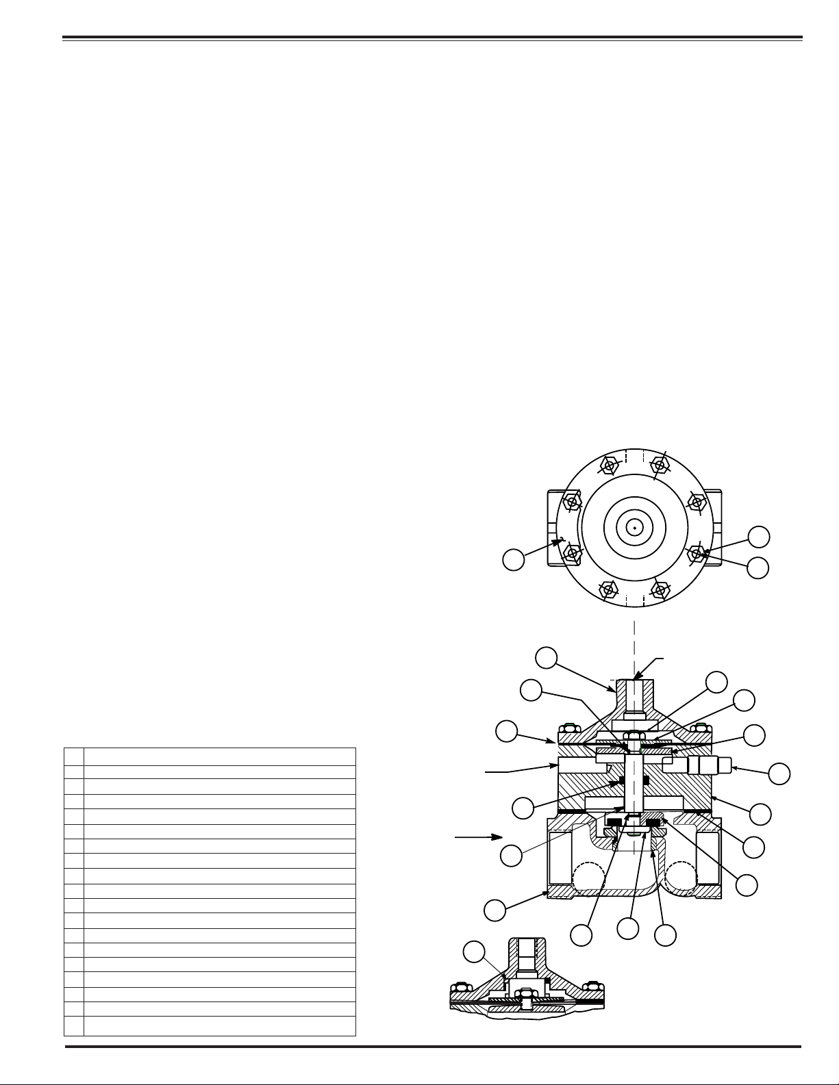
100-02 POWERTROL
VALVE SIZES 1/2" & 3/4"
INLET
6. Replace cover chamber spring on the upper diaphragm
washer. NOTE: Some valves may not have a cover chamber spring.
7. Place the cover on the power unit body aligning the
index marks. Secure the cover with 8 stud nuts. Tighten
the nuts firmly with a cross-over pattern until all nuts are
tight:
8. Reinstall the control system and tubing exactly as it was
before disassembly.
ITEM
NO.
1 HEX NUT 10-32 (8)
2 COVER
3 POWER UNIT BODY
4 HEX NUT 1/4-28-NF-2 A.S.F. JAM
5 DIAPHRAGM WASHER (UPPER)
6 DIAPHRAGM
7 DIAPHRAGM WASHER (LOWER)
8 STEM
9 DISC GUIDE
10 DISC RETAINER ASSEMBLY
11 "O" RING
12 BODY TO BODY GASKET
13 STUD 10-32 (8)
14 PIPE PLUG 1/8 NPT
15 BODY
16 SPRING (USED ON 100-02KHR & 100-02 KHX
17 "O" RING
18 SEAT
19 NAMEPLATE
DESCRIPTION
19
2
17
6
1/8 NPT (THESE
TAPPED HOLES ARE
SHOWN 90" FROM
TRUE POSITION)
11
INLET
8
15
16
MODELS 100-02KH 100-02KHR, 100-02KHX
17
1
13
1/8 NPT
4
5
7
14
3
12
10
9
18
Page 5
USEFUL INFORMATION OR HINTS
1. The approximate volume of liquid discharged from
the chamber above the diaphragm when the valve
moves from the fully closed positions to the fully open
is as follows:
VALVE SIZE DISPLACEMENT
1/2"
3/4"
1"
1 1/4"
1 1/2"
2"
2 1/2"
3"
4"
6"
8'
10"
12"
14"
16"
0.340 Fl. Oz
0.340 Fl. Oz.
0.700 Fl. Oz.
0.020 Gal.
0.020 Gal.
0.032 Gal.
0 043 Gal
0.080 Gal
0.169 Gal.
0 531 Gal.
1.260 Gal
2.510 Gal.
4.000 Gal.
6.500 Gal.
9.570 Gal.
.01 Liters
.01 Liters
.02 Liters
.10 Liters
.10 Liters
.10 Liters
.20 Liters
.30 Liters
.60 Liters
2.00 Liters
4.75 Liters
9.50 Liters
15.14 Liters
24.60 Liters
36.20 Liters
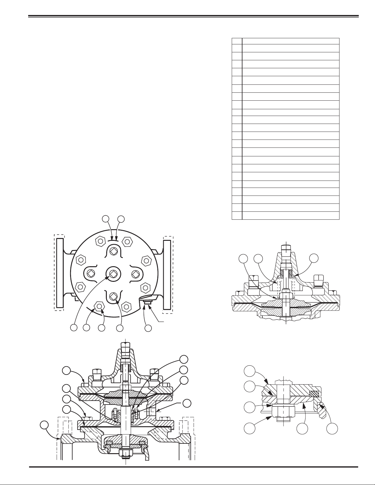
100-02 POWERTROL
VALVE SIZES 1" - 3"
14
38
ITEM
NO.
1 CENTER COVER PLUG
2 COVER PLUG
3 STUD NUT
7 PLUG, PIPE, BODY
10 * GASKET "O" RING
14 NAMEPLATE
15 * O-RING, STEM
16 RETAINER BEARING (1”-3” ONLY)
19 BOLT, HEX HD. (1”-3” ONLY)
20 POWERUNIT BODY
21 LOWER STEM NUT
22 SPACER WASHER
24 DISC GUIDE
25 DISC RETAINER
30 BODY
31 SPRING (100-02KH/100PAKH ONLY)
32 LOCK WASHER - SPRING
33 * SEAT O-RING
34 * GASKET BEARING GASKET (1”-3" ONLY)
35 Screw Fil. HD. (1’-2 1⁄2”) / BOLT HEX. (3”)
36 UPPER WASHER SPRING (100PKCH)
37 LOWER WASHER SPRING (100PAKCH)
38 DRIVE SCREW
* RECOMMENDED SPARE PARTS
PART DESCRIPTION
30
13 2
19
34
19
10
19
31
37
J
NPT
36
7
Model 100-02KH
16
35
15
25
22
20
32
21
24
33
Seat & Disc Details
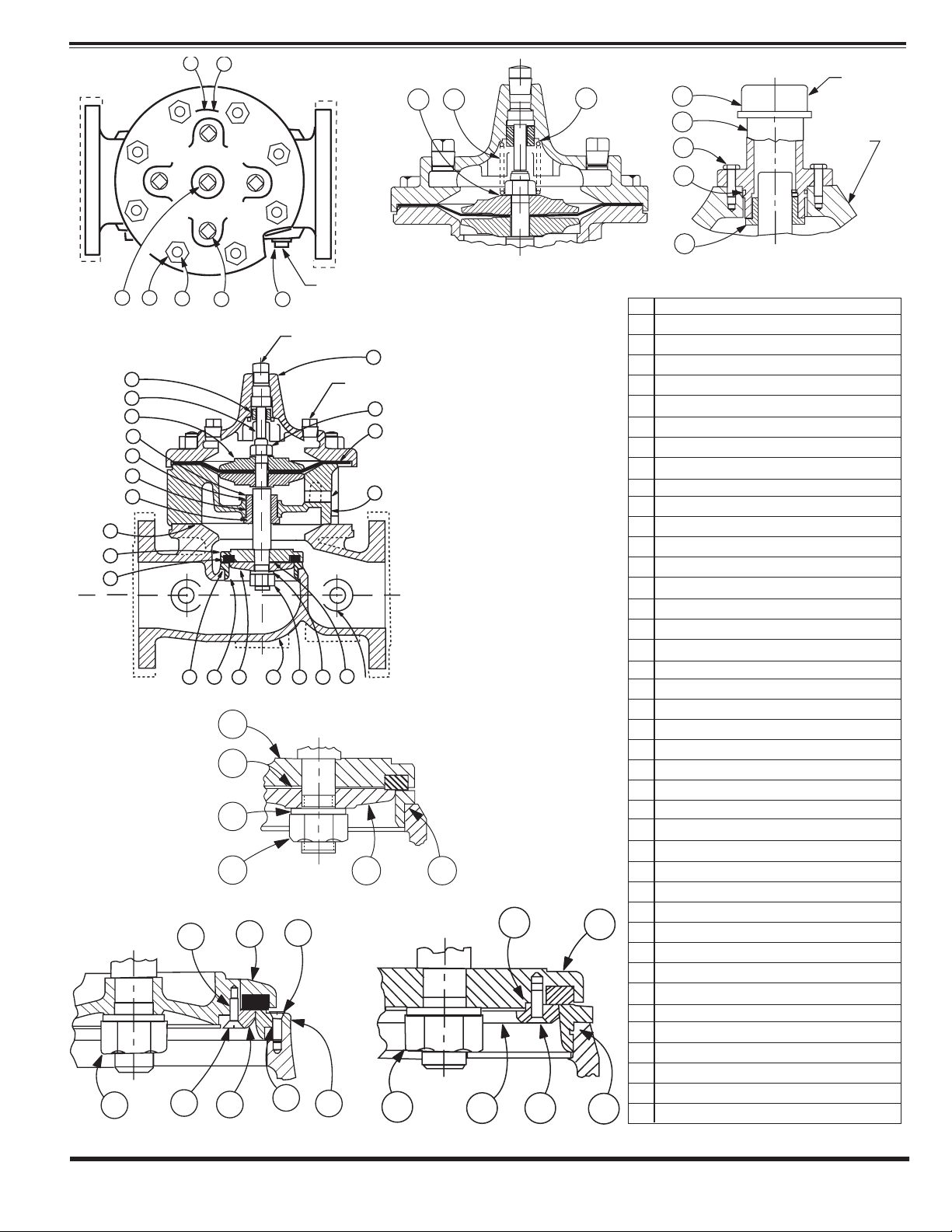
Page 6
CLA-VAL
Copyright Cla-Val 2008 Printed in USA Specifications subject to change without notice.
P.O. Box 1325 • Newport Beach, CA 92659-0325 • Phone: 949-722-4800 • Fax: 949-548-5441 • E-mail: claval@cla-val.com • Website cla-val.com
©
14
38
G
NPT
COVER
37
31
36
6
39
8
9
4
13 2
4
27
12
17
16
18
15
10
25
26
INLET
19
33
22
21
23
J
NPT
7
J
NPT
5
K
NPT
11
13
20
OUTLET
24
29
21
30
32
22
H
NPT
25
22
32
21
24
25
28
33
29
24
21
33
24
22
23
ITEM
NO.
1 CENTER COVER PLUG
2 COVER PLUG
3 STUD NUT
4 COVER BEARING
5 COVER
6 PIPE CAP (16" ONLY)
7 PLUG, PIPE, BODY
8 BOLT HEX HD (16" ONLY)
9 * O-RING (16" ONLY)
10 * GASKET "O" RING
11 UPPER STEM NUT
12 UPPER DlAPHRAGM WASHER
13 * DIAPHRAGM
14 NAMEPLATE
15 * O-RING, STEM
16 RETAINER BEARING (1”-3” ONLY)
RING RETAINER BEARING (4”-16” ONLY)
17 POWERUNIT BEARING
18 * O-RING BEARING (4”-16” ONLY)
19 BOLT, HEX HD. (1”-3” ONLY)
STUD (4”-16” ONLY
20 POWERUNIT BODY
21 LOWER STEM NUT
22 SPACER WASHER
23 DISC GUIDE SCREW (6" - 16" ONLY)
24 DISC GUIDE
25 DISC RETAINER
26 * DISC
27 STEM
28 SEAT SCREW (8”-16” ONLY)
29 SEAT
25
30 BODY
31 SPRING (100-02KH/100PAKH ONLY)
32 LOCK WASHER - SPRING
33 * SEAT O-RING
34 * GASKET BEARING GASKET (1”-3" ONLY)
35 Screw Fil. HD. (1’-2 1⁄2”) / BOLT HEX. (3”)
36 UPPER WASHER SPRING (100PKCH)
37 LOWER WASHER SPRING (100PAKCH)
38 DRIVE SCREW
33
39 COVER BEARING HOUSING (16" ONLY)
* RECOMMENDED SPARE PARTS
PART DESCRIPTION
N-100-02 (R-1/08)
 Loading...