

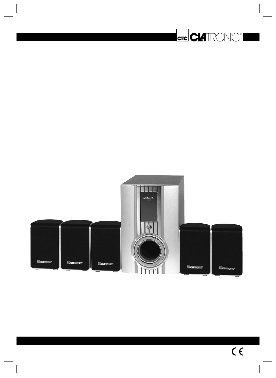
Page 1
Bedienungsanleitung/Garantie
Gebruiksaanwijzing/Garantie • Mode d’emploi/Garantie
Instrucciones de servicio/Garantía • Istruzioni per l’uso/Garanzia
Instruction Manual/Guarantee • Instrukcja obsługi/Gwarancja
A használati utasítás/Garancia
Funk-Surround-Lautsprechersystem
Wireless Surround-luidsprekersysteem • Système de haut-parleurs son sans fi l
Sistema Wireless de Altavoz Surround • Sistema di altoparlanti Surround senza fi li
Wireless Surround Speaker System • Bezprzewodowy zestaw głośników surround
Wireless Surround- hangszóró-rendszer
SLS 693
05-SLS 693 Neu 1 09.02.2006, 10:33:49 Uhr
Page 2

05-SLS 693 Neu 2 09.02.2006, 10:33:52 Uhr
Page 3

DEUTSCH
ITALIANO
DEUTSCHNEDERLANDSFRANÇAISESPAÑOLITALIANOENGLISHJE˛ ZYK POLSKIMAGYARUL
Inhalt
Bedienungsanleitung........................................ Seite 4
Technische Daten............................................. Seite 7
Garantie............................................................ Seite 7
NEDERLANDS
Inhoud
Gebruiksaanwijzing ....................................... Pagina 8
Technische gegevens.................................... Pagina 11
Garantie......................................................... Pagina 11
FRANÇAIS
Sommaire
Mode d’emploi .................................................. Page 12
Données techniques......................................... Page 15
Garantie............................................................ Page 15
Indice
Istruzioni per l’uso.......................................... Pagina 20
Dati tecnici..................................................... Pagina 23
Garanzia........................................................ Pagina 23
ENGLISH
Contents
Instruction Manual ............................................ Page 24
Technical Data.................................................. Page 27
Guarantee......................................................... Page 27
JE˛ ZYK POLSKI
Spis tres´ci
Instrukcja obsługi............................................ Strona 28
Dane techniczne............................................. Strona 31
Gwarancja ......................................................Strona 31
ESPAÑOL
Indice
Instrucciones de servicio ............................... Página 16
Datos técnicos............................................... Página 19
Garantia......................................................... Página 19
05-SLS 693 Neu 3 09.02.2006, 10:33:52 Uhr
Tartalom
A hasznalati utasítás ........................................Oldal 32
Műszaki adatok................................................. Oldal 35
Garancia........................................................... Oldal 35
MAGYARUL
3
Page 4
Allgemeine Sicherheitshinweise
Um das Risiko von Feuer oder einem elektrischen Schlag
zu vermeiden, sollten Sie das Gerät nicht Regen oder
Feuchtigkeit aussetzen. Das Gerät nicht in unmittelbarer Nähe von Wasser betreiben (z.B. Badezimmer,
DEUTSCH
Schwimmbecken, feuchte Keller).
Verwenden Sie das Gerät nur für den vorgesehenen
Zweck.
Das Gerät ausschließlich an eine vorschriftsmäßig
installierte Steckdose anschließen. Achten Sie darauf,
dass die angegebene Spannung mit der Spannung der
Steckdose übereinstimmt.
Bei Verwendung von externen Netzteilen auf die richtige
Polarität und Spannung achten, Batterien stets richtigherum einlegen.
Das Gerät so aufstellen, dass vorhandene Lüftungsöffnungen nicht verdeckt werden.
Niemals das Gehäuse des Gerätes öffnen. Durch unsachgemäße Reparaturen können erhebliche Gefahren
für den Benutzer entstehen. Bei Beschädigung des
Gerätes, insbesondere des Netzkabels, das Gerät nicht
mehr in Betrieb nehmen, sondern von einem Fachmann
reparieren lassen. Netzkabel regelmäßig auf Beschädigungen prüfen.
Ein defektes Netzkabel darf nur vom Hersteller, unserem
Kundendienst oder einer ähnlich qualifi zierten Person
durch ein gleichwertiges Kabel ersetzt werden, um Gefährdungen zu vermeiden.
Benutzen Sie das Gerät längere Zeit nicht, ziehen Sie
den Netzstecker aus der Steckdose, bzw. entnehmen Sie
die Batterien.
Diese Symbole können sich ggfs. auf dem Gerät befi nden
und sollen Sie auf folgendes hinweisen:
Das Blitz-Symbol soll den Benutzer auf Teile
im Inneren des Gerätes hinweisen, die gefährlich hohe Spannungen führen.
Das Symbol mit Ausrufezeichen soll den
Benutzer auf wichtige Bedienungs- oder
Wartungs-Hinweise in den Begleitpapieren
hinweisen.
Spezielle Sicherheitshinweise
• Zur Sicherheit Ihrer Kinder lassen Sie keine Verpackungsteile (Plastikbeutel, Karton, Styropor, etc.)
erreichbar liegen.
Achtung! Lassen Sie kleine Kinder nicht mit Folie
spielen. Es besteht Erstickungsgefahr!
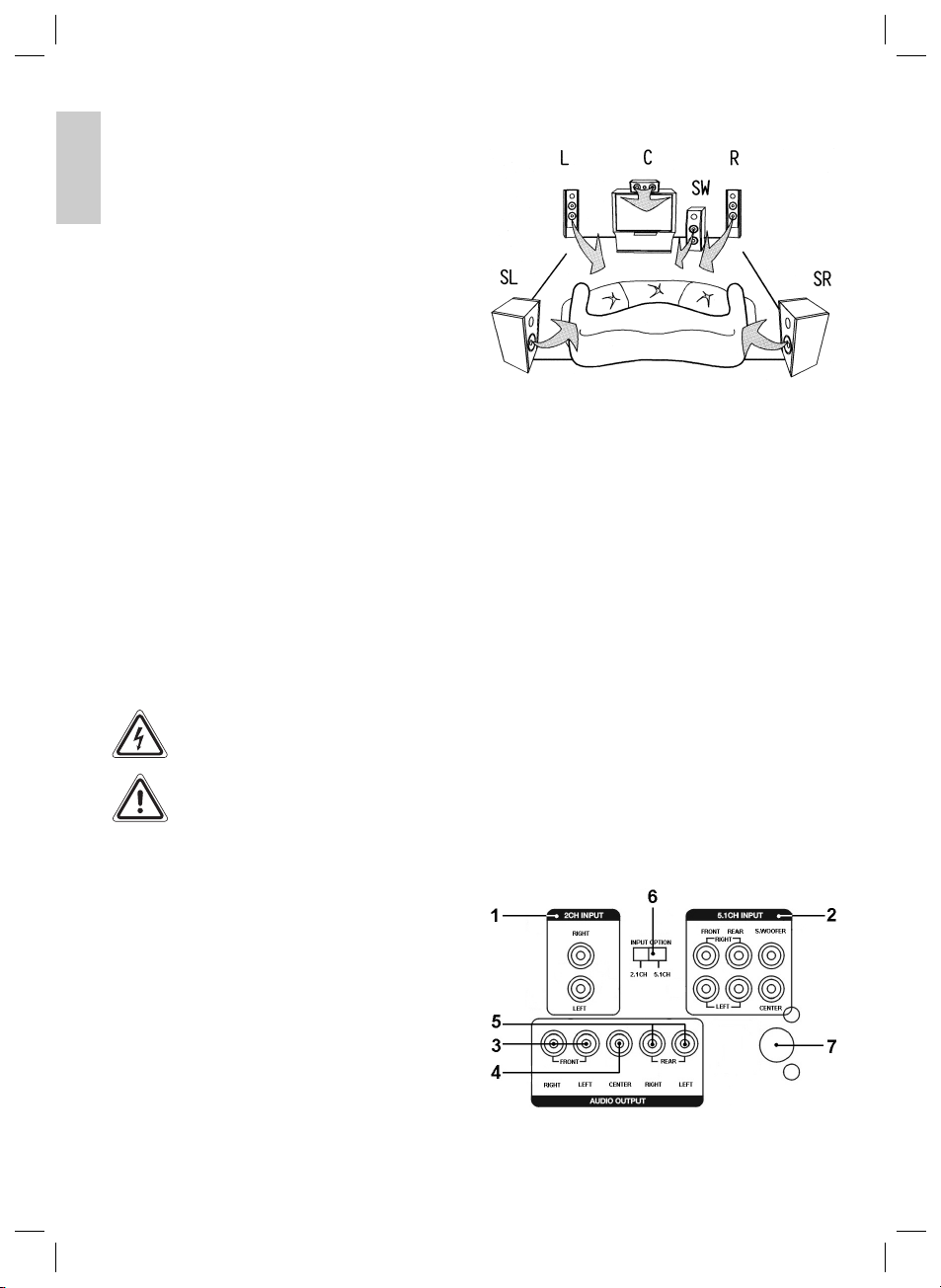
Eine optimale Aufstellung der Lautsprecherboxen
kann wie folgt aussehen:
Anschließen
Hinweis: Achten Sie darauf, dass die Steckverbindungen
fest sitzen. Schlechte Verbindungen können zu Störgeräuschen führen.
1 2CH INPUT
Dient zum Anschluss einer externen Klangquelle über
Cinch (z.B. Hifi -Videorekorder).
2 5.1CH INPUT
Dient zum Anschluss einer externen Klangquelle mit
einem 5.1-Ausgang (z.B. DVD-Player).
3 FRONT RIGHT/LEFT
Ausgang rechts und links zum Anschluss der Frontlautsprecherboxen (Front left Channel, Front right
Channel).
4 CENTER
Ausgang zum Anschluss der Centerlautsprecherbox
(Center Channel).
5 REAR RIGHT/LEFT
Ausgang zum Anschluss der Surroundlautsprecherboxen rechts und links (Surround right speaker,
Surround left speaker).
6 2.1CH/ 5.1CH Schalter
Dient zum Umschalten zwischen dem 2.1CH-Eingang
und dem 5.1CH-Eingang.
7 Netzkabel
Hinweis: Der Netzschalter zum Ein- und Ausschalten
des Gerätes, befi ndet sich auf der Gerätevorderseite
(ohne Abbildung).
Aufbauen
• Entnehmen Sie alle Geräte der Verpackung und
legen Sie das Innenverpackungsmaterial zurück in
den Karton.
• Verwahren Sie die Verpackung nach Möglichkeit
während der gesamten Garantie auf!
• Stecken Sie den Stecker des Subwoofers erst in
die Steckdose, wenn alle Lautsprecherboxen und
Anschlüsse korrekt verkabelt sind!
4
05-SLS 693 Neu 4 09.02.2006, 10:33:53 Uhr
Page 5
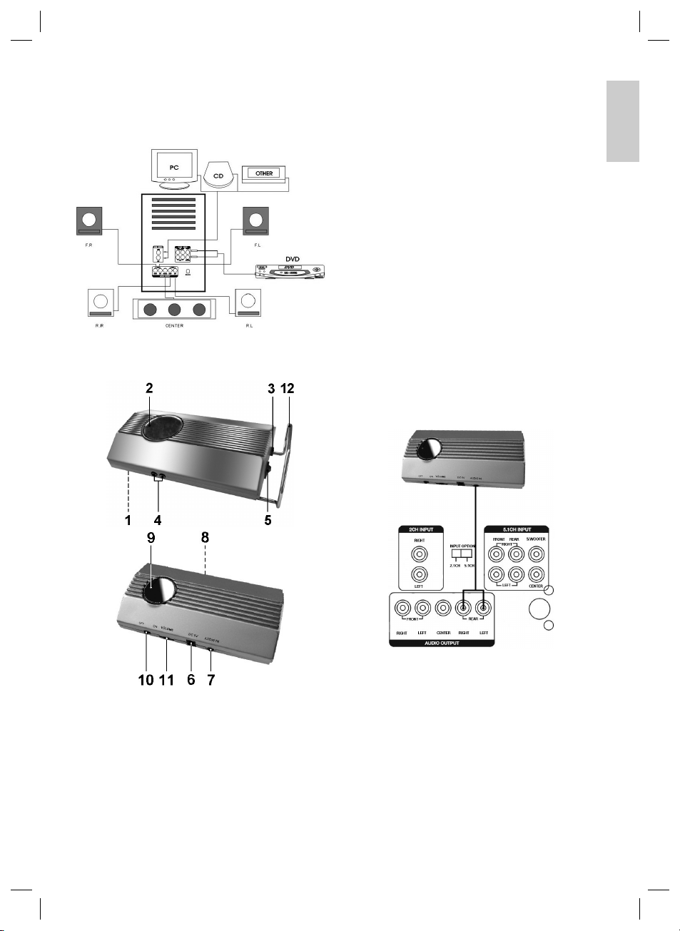
Die korrekte Verkabelung sieht wie folgt aus:
Wenn Sie alle Lautsprecherboxen und Geräte wie beschrieben angeschlossen haben, können Sie den Netzstecker des Subwoofers in eine vorschriftsmäßig installierte
Schutzkontaktsteckdose 230 V, 50 Hz einstecken.
Optionaler Anschluss der Rear-/oder
Front-Lautsprecher mit dem Transmitter
7 AUDIO IN
3,5mm Klinkenbuche Audioeingang
8 FREQUENCY SELECT Knopf
Zum Angleichen des Kanals
9 POWER Kontrollleuchte
10 ON / OFF
Ein/Aus Schalter
11 VOLUME
Lautstärkeregler
12 Standfuß
Allgemeine Informationen
• Die Audiosignale werden vom Sender zum Empfänger übertragen. Reichweite innerhalb von Gebäuden
ca. 30 m. Je nach Umgebungsbedingungen kann die
Reichweite geringer ausfallen.
• Die Audiosignale werden im 2,4 GHz-Bereich übertragen.
• Kompressionsfreie High-Sound Qualität mit 0,5 ms
Verzögerungszeit.
• Die Audiosignale werden digital mit einer Abtastrate
von 44,1 KHz und 16-bit verarbeitet.
• Sollten Störungen oder schlechter Empfang die
Übertragung beeinfl ussen, aktiviert das Gerät eine
Stummschaltung (siehe Abschnitt „Schlechte Empfangsqualität“).
Anschluss des Senders (Transmitter)
Sender
DEUTSCH
• Verbinden Sie den 3,5 mm Klinkenstecker mit der
AUDIO IN Buche am Sender.
1 SCAN
Taste zum Aktivieren der Kanalsuche
2 Bereitschaftskontrollanzeige
3 AC 230 V / 50 Hz
Netzkabel
4 R OUT / L OUT (RIGHT/LEFT)
Lautsprecherausgang (rechts/links)
5 POWER ON / OFF
Ein/Aus Schalter
6 DC 5V IN Anschlussbuchse
05-SLS 693 Neu 5 09.02.2006, 10:33:55 Uhr
• Schließen Sie nun die Cinchstecker an den AUDIO
OUTPUT REAR RIGHT/LEFT des Subwoofers an.
Hinweis: Sie können auch wahlweise die Front-
lautsprecher anschließen. Verbinden Sie dann bitte
die Cinchstecker mit den AUDIO OUTPUT FRONT
RIGHT/LEFT Anschlüssen.
• Stecken Sie das Netzteil in den dafür vorgesehene
DC 5 V Anschluss und dann in eine vorschriftsmäßig
installierte 230 V/50 Hz Schutzkontaktsteckdose.
5
Page 6
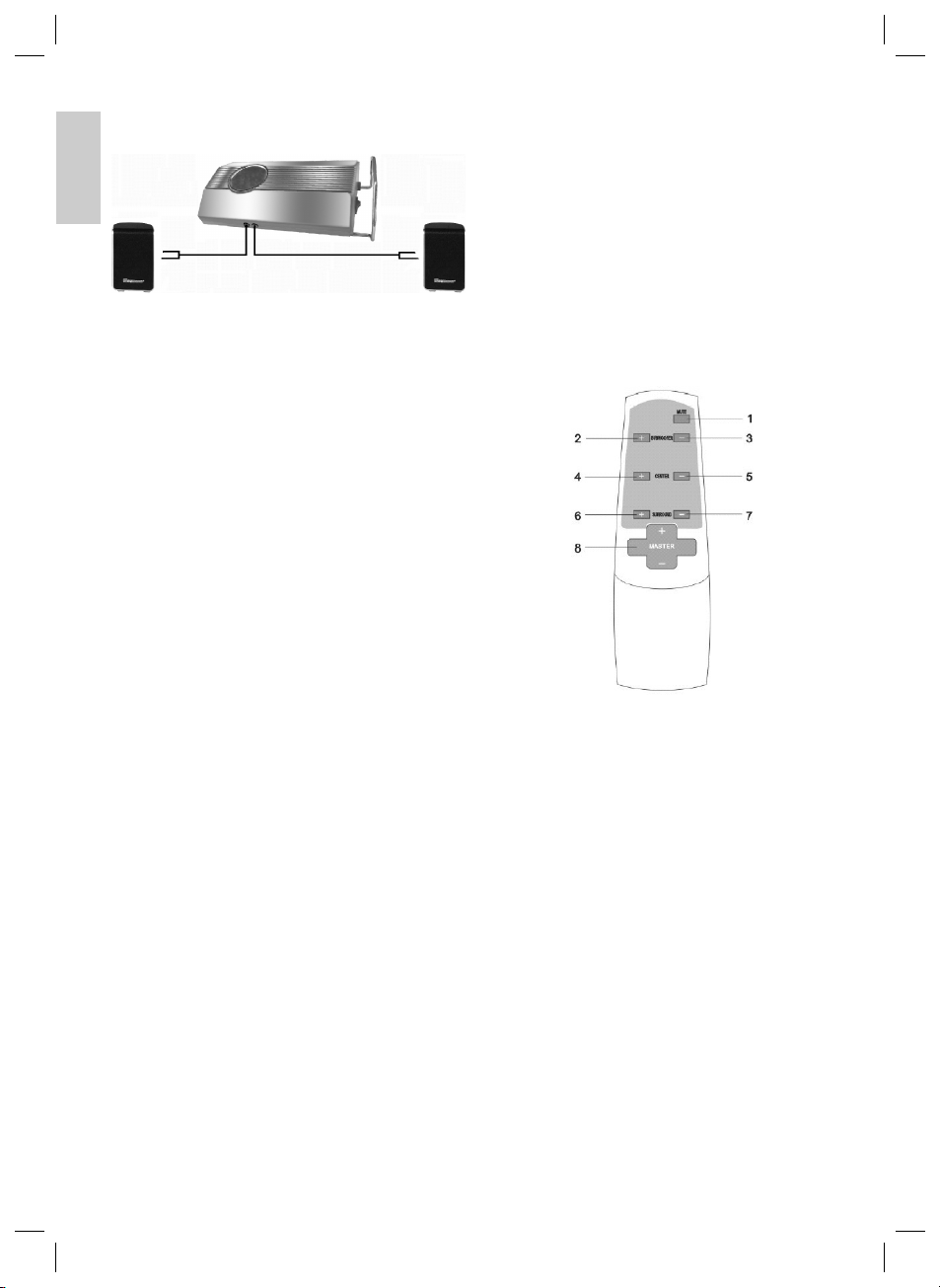
Anschluss des Empfängers (Receiver)
Empfänger
DEUTSCH
• Verbinden Sie die Surround- oder Front-Lautsprecherboxen mit den R OUT / L OUT (rechts/links) des
Empfängers.
• Stecken Sie das Netzkabel in eine gut erreichbare
Steckdose und schalten Sie den Empfänger ein.
Hinweis: Mit dem VOLUME Lautstärkeregler (11) können
Sie die Lautstärke, der an dem Empfänger angeschlossenen Lautsprecherboxen, individuell einstellen.
Kanaleinstellung
• Betätigen Sie die FREQUENCY SELECT Taste an
der Unterseite des Senders. Anschließend drücken
Sie bitte die SCAN Taste am Empfänger.
• Durch erneutes Drücken der SCAN Taste wird der
nächste Kanal angewählt.
• Die Änderung der Kanaleinstellung ist auch bei einer
Empfangsbeeinträchtigung gegebenenfalls erforderlich.
Störungsbehebung
Keine Audioübertragung
• Ist das Netzteil/Netzkabel eingesteckt? Kontrollieren
Sie sowohl am Sender als auch am Empfänger den
Anschluss.
• Ist der Empfänger eingeschaltet? Schalten Sie den
Empfänger mit dem Netzschalter, auf der Rückseite
des Gerätes, ein.
• Ist die Übertragungsquelle eingeschaltet? Falls nicht,
schalten Sie diese bitte ein.
• Mauern und Decken verringern die Reichweite.
• Überprüfen Sie an den angeschlossenen Geräten die
Verbindungen.
• Überprüfen Sie ob die Signalquelle (z.B. DVD Player)
auf Surround-Wiedergabe eingestellt ist.
Schlechte Empfangsqualität
• Richten Sie Sender und Empfänger noch einmal
aufeinander aus.
• Verändern Sie die Position des Senders und Empfängers ein wenig.
• Durch Wechselwirkung mit anderen Funkanlagen, wie
schnurlose Haustelefone, Handys oder CB-Funk kann
es zu Beeinträchtigungen kommen.
Fernbedienung
Batterien einlegen
(Batterien nicht im Lieferumfang enthalten)
• Öffnen Sie den Batteriefachdeckel auf der Rückseite
der Fernbedienung.
• Legen Sie 2 Micro Batterien des Typs LR3 „AAA“
1,5V ein. Achten Sie auf die richtige Polarität (siehe
Batteriefachboden)!
6
• Wird die Fernbedienung längere Zeit nicht genutzt,
entnehmen Sie bitte die Batterien, um ein „Auslaufen“
von Batteriesäure zu vermeiden.
• Ungleiche Batterietypen oder neue und gebrauchte
Batterien dürfen nicht zusammen verwendet werden.
Achtung: Batterien gehören nicht in den Hausmüll. Bitte
geben Sie verbrauchte Batterien bei zuständigen Sammelstellen oder beim Händler ab.
Werfen Sie Batterien niemals ins Feuer.
Bei Verwendung der Fernbedienung sollten Sie darauf
achten, dass zwischen Fernbedienung und Subwoofer keine Gegenstände (z.B. Tisch, Stuhl, usw.) gestellt werden.
Diese Gegenstände verhindern, dass der Infrarotlichtstrahl
der Fernbedienung zum Empfänger des Subwoofers
gelangt. Eine Steuerung ist dann nicht möglich.
1 MUTE
Mit dieser Taste können Sie die Lautsprecher, ohne
die Lautstärke zu verändern, ausschalten (die Betriebszustands LED des Subwoofers blinkt).
Hinweis: Achten Sie beim Ausschalten dieser
Funktion darauf, dass die Gesamtlautstärke nicht auf
maximal gestellt wurde!
2 SUBWOOFER +
Mit dieser Taste können Sie die Lautstärke des Subwoofers erhöhen.
3 SUBWOOFER -
Mit dieser Taste können Sie die Lautstärker des
Subwoofers verringern.
4 CENTER +
Mit dieser Taste können Sie die Lautstärke des
Center erhöhen.
5 CENTER -
Mit dieser Taste können Sie die Lautstärke des
Center verringern.
6 SR +
Mit dieser Taste können Sie die Lautstärke des Surroundlautsprechers erhöhen.
7 SR -
Mit dieser Taste können Sie die Lautstärke des Surroundlautsprechers verringern.
8 MASTER +/-
Tasten zur Lautstärkeeinstellung.
05-SLS 693 Neu 6 09.02.2006, 10:33:56 Uhr
Page 7
Inbetriebnahme
Stecken Sie den Netzstecker in eine vorschriftsmäßig
installierte Schutzkontaktsteckdose 230 V, 50 Hz.
1. Schalten Sie Ihre Klangquelle (z.B. DVD-Player) ein
und starten Sie diese.
2. Schalten Sie den Subwoofer, mit dem Ein-Ausschalter
auf der Vorderseite des Gerätes, ein.
3. Stellen Sie über den 2.1CH /5.1CH Schalter die
Eingangsquelle ein.
4. Mit dem MASTER +/- Regler an der Fernbedienung,
können Sie die Gesamtlautstärke einstellen.
5. Durch Drücken der Tasten 2 bis 7 an der Fernbedienung können Sie die Lautstärke der Center, Surround
und Subwoofer Lautsprecher einstellen.
6. Möchten Sie den Betrieb beenden, schalten Sie den
Subwoofer mit dem Ein-/ Ausschalter aus.
Technische Daten
Modell: .................................................................SLS 693
Spannungsversorgung: .................................230 V, 50 Hz
Leistungsausgänge
L, R, C, LS, RS: ................................ 5 x 40 W PMPO
Subwoofer:............................................. 300 W PMPO
Rauschabstand:........................................................60 dB
FST:
Sender
Spannungsversorgung: ..........................................DC 5 V
Kanäle:...........................................................................16
Frequenzbereich:................................2400 ~ 2483,5 MHz
Eingangspegel:.............................................4 V pp (max.)
Ausgangsimpedanz:.........................................> 10 kOhm
Empfänger
Spannungsversorgung: .................................230 V, 50 Hz
Kanäle:...........................................................................16
Frequenzbereich:................................2400 ~ 2483,5 MHz
Ausgangsimpedanz:...........................................< 1 kOhm
Übersprechen R/L: ................................................> 15 dB
Technische Änderungen vorbehalten!
Konformitätserklärung
Hiermit erklärt die Firma Clatronic GmbH, dass sich das
Gerät SLS 693 in Übereinstimmung mit den grundlegenden Anforderungen und den anderen relevanten
Vorschriften der R.E.T.T.E Richtlinie 1999/5/EG, der
europäischen Richtlinie für elektromagnetische Verträglichkeit (89/336/EWG) und der Niederspannungsrichtlinie
(93/68/EWG) befi ndet.
Eine Kopie der Konformitätserklärung können Sie über
die Telefonnummer 0 21 52/20 06-666 beziehen.
Garantie
Wir übernehmen für das von uns vertriebene Gerät eine
Garantie von 24 Monaten ab Kaufdatum (Kassenbon).
Innerhalb der Garantiezeit beseitigen wir unentgeltlich
die Mängel des Gerätes oder des Zubehörs*), die auf
Material- oder Herstellungsfehler beruhen, durch Reparatur oder, nach unserem Ermessen, durch Umtausch.
Garantieleistungen bewirken weder eine Verlängerung
der Garantiefrist, noch beginnt dadurch ein Anspruch auf
eine neue Garantie!
Als Garantienachweis gilt der Kaufbeleg. Ohne diesen
Nachweis kann ein kostenloser Austausch oder eine
kostenlose Reparatur nicht erfolgen.
Im Garantiefall geben Sie bitte das komplette Gerät in
der Originalverpackung zusammen mit dem Kassenbon
an Ihren Händler.
*) Schäden an Zubehörteilen führen nicht automatisch
zum kostenlosen Umtausch des kompletten Gerätes.
Wenden Sie sich in desem Fall bitte an unsere Hotline!
Glasbruchschäden bzw. Brüche von Kunststoffteilen sind
grundsätzlich kostenpfl ichtig!
Sowohl Defekte an Verbrauchszubehör bzw. Verschleißteilen (z.B. Motorkohlen, Knethaken, Antriebsriemen,
Ersatzfernbedienung, Ersatzzahnbürsten, Sägeblättern
usw.), als auch Reinigung, Wartung oder der Austausch
von Verschleißteilen, fallen nicht unter die Garantie und
sind deshalb kostenpfl ichtig!
Die Garantie erlischt bei Fremdeingriff.
Nach der Garantie
Nach Ablauf der Garantiezeit können Reparaturen
kostenpfl ichtig vom entsprechenden Fachhandel oder
Reparaturservice ausgeführt werden.
Bedeutung des Symbols „Mülltonne“
Schonen Sie unsere Umwelt, Elektrogeräte gehören nicht
in den Hausmüll.
Nutzen Sie die für die Entsorgung von Elektrogeräten
vorgesehenen Sammelstellen und geben dort Ihre Elektrogeräte ab die Sie nicht mehr benutzen werden.
Sie helfen damit die potenziellen Auswirkungen, durch
falsche Entsorgung, auf die Umwelt und die menschliche
Gesundheit zu vermeiden.
Sie leisten damit Ihren Beitrag zur Wiederverwertung,
zum Recycling und zu anderen Formen der Verwertung
von Elektro- und Elektronik-Altgeräten.
Informationen, wo die Geräte zu entsorgen sind, erhalten
Sie über Ihre Kommunen oder die Gemeindeverwaltungen.
In vielen Ländern der EU ist die Entsorgung von Elektro- und Elektronik-Altgeräten über den Haus- und/oder
Restmüll ab 13.8.2005 verboten.
In Deutschland ab 23.3.2006.
DEUTSCH
7
05-SLS 693 Neu 7 09.02.2006, 10:33:58 Uhr
Page 8
Algemene veiligheidsinstructies
Voorkom risico’s voor brand en elektrische schokken en
stel het apparaat niet bloot aan regen of vocht. Gebruik
het apparaat niet in de directe nabijheid van water (bijv.
badkamer, zwembad, vochtige kelder).
Gebruik het apparaat uitsluitend voor het daarvoor
bestemde doel.
Sluit het apparaat uitsluitend aan op een correct geïnstalleerde contactdoos. Let op dat de aangegeven spanning
overeenstemt met de spanning van de contactdoos.
Let bij het gebruik van externe adapters op de juiste
polariteit en spanning en plaats batterijen altijd in de
juiste richting.
NEDERLANDS
Plaats het apparaat zodanig dat de aangebrachte luchtopeningen niet worden afgedekt.
Open nooit de behuizing van het apparaat. Door ondeskundige reparaties kunnen aanzienlijke gevaren voor
de gebruiker ontstaan. Neem het apparaat niet meer in
gebruik wanneer het apparaat - en in het bijzonder de
kabel - beschadigingen vertoont, maar laat het eerst door
een vakman repareren. Controleer de kabel regelmatig
op beschadigingen.
Een defecte kabel mag alleen door de fabrikant, onze
technische dienst of een soortgelijk gekwalifi ceerd
persoon worden vervangen. Alleen zo kunnen gevaren
vermeden worden.
Onderbreek de stroomtoevoer of verwijder de batterijen wanneer u denkt, het apparaat langere tijd niet te
gebruiken.
Volgende symbolen kunnen op uw apparaat zijn aangebracht. Zij hebben de volgende betekenis:
Het bliksemsymbool wijst de gebruiker op
onderdelen in het inwendige van het apparaat
die gevaarlijk hoge spanning voeren.
Het symbool met het uitroepteken verwijst
naar belangrijke bedienings- en onderhoudsinstructies in de begeleidende documentatie.
Speciale veiligheidsinstructies
• Laat om veiligheidsredenen geen verpakkingsdelen
(plasticzak, doos, piepschuim, enz.) binnen het bereik
van uw kinderen liggen.
Let op! Laat kleine kinderen niet met de folie spelen.
Er bestaat gevaar voor verstikking!
Een optimale plaatsing van de luidsprekerboxen kan
er als volgt uitzien:
Aansluiten
Opmerking: let op dat de steekverbindingen vast gemon-
teerd zijn. Slechte verbindingen kunnen tot storingsgeluiden leiden.
1 2CH INPUT
Is bedoeld voor de aansluiting op een externe geluidsbron via cinch (bijv. hifi -videorecorder).
2 5.1CH INPUT
Is bedoeld voor de aansluiting op een externe geluidsbron met een 5.1 uitgang (bijv. DVD-speler).
3 FRONT RIGHT/LEFT
Uitgang rechts en links voor de aansluiting van
de frontluidsprekers (front left channel, front right
channel).
4 CENTER
Uitgang voor de aansluiting van de centerluidsprekers
(center channel).
5 REAR RIGHT/LEFT
Uitgang voor de aansluiting van de surroundluidsprekers rechts en links (surround rigth speaker, surround
left speaker).
6 2.1CH/ 5.1CH schakelaar
Is bedoeld voor het omschakelen tussen de
2.1CH-ingang en de 5.1CH-ingang.
7 Netkabel
Opmerking: de netschakelaar voor het in- en uitschake-
len van het apparaat bevindt zich op de apparaatvoorzijde (zonder afbeelding).
Montage
• Verwijder alle apparaten uit de verpakking en plaats
het binnenverpakkingsmateriaal terug in het karton.
• Bewaar de verpakking indien mogelijk gedurende de
hele garantieperiode!
• Steek de steker van de subwoofer pas in de contactdoos wanneer alle luidsprekerboxen en aansluitingen
correct verbonden zijn!
8
05-SLS 693 Neu 8 09.02.2006, 10:33:59 Uhr
Page 9
De correcte aansluiting ziet er als volgt uit:
Wanneer u alle luidsprekers en apparaten zoals
beschreven hebt aangesloten, kunt u de netsteker van
de subwoofer in een correct geïnstalleerde en geaarde
contactdoos, 230V, 50Hz steken.
Optionele aansluiting van de rear- of
frontluidsprekers met de transmitter
7 AUDIO IN
3,5 mm-stekkerbus audio-ingang
8 FREQUENCY SELECT-knop
om het kanaal terug te zetten
9 POWER-controlelampje
10 ON / OFF
Aan-/uitschakelaar
11 VOLUME
Volumeregelaar
12 Standvoet
Algemene informatie
• De audiosignalen worden van de zender naar de
ontvanger gezonden. Reikwijdte binnen gebouwen
ca. 30 m. Al naargelang de omgevingsvoorwaarden
kan de reikwijdte minder zijn.
• De audiosignalen worden overgedragen in het
2,4 GHz-bereik.
• Compressievrije High-Sound-kwaliteit met 0,5 ms
vertragingstijd.
• De audiosignalen worden digitaal verwerkt met een
aftastsnelheid van 44,1 KHz en 16-bit.
• Wanneer storingen of een slechte ontvangst de
overdracht beïnvloeden, activeert het apparaat een
stomschakeling (zie onder “Slechte ontvangstkwali-
teit”).
Aansluiting van de zender (transmitter)
Zender
NEDERLANDS
• Verbind de 3,5 mm-klinkstekker met de AUDIO IN-
bus aan de zender.
1 SCAN
Toets voor het activeren van de kanaalzoekfunctie
2 Powercontrole-indicatie
3 AC 230 V / 50 Hz
Netkabel
4 R OUT / L OUT (RIGHT/LEFT)
Luidsprekeruitgang (rechts/links)
5 POWER ON / OFF
Aan.-/uitschakelaar
6 DC 5V IN aansluitbus
05-SLS 693 Neu 9 09.02.2006, 10:34:00 Uhr
• Sluit nu de cinchstekker aan op de AUDIO OUTPUT
REAR RIGHT/LEFT van de subwoofer.
Opmerking: Desgewenst kunt u ook de frontluidspre-
kers aansluiten. In dat geval verbindt u de cinchstekker met de AUDIO OUTPUT FRONT RIGHT/LEFT
-aansluitingen.
• Steek de netadapter in een daarvoor bestemde DC
5V-aansluiting en vervolgens in een correct geïnstalleerde 230V/50HZ contactdoos.
9
Page 10
Aansluiting van de ontvanger (receiver)
Ontvanger
• Verbind de surround- of frontluidsprekers met de
R OUT / L OUT (rechts / links) van de ontvanger.
NEDERLANDS
• Sluit de netsteker aan op een goed bereikbare contactdoos en schakel de ontvanger in.
Opmerking: met de VOLUME-regelaar (11) kunt u de
geluidssterkte van de op de ontvanger aangesloten
luidsprekers individueel instellen.
Kanaalinstelling
• Druk op de FREQUENCY SELECT-toets aan de
onderzijde van de zender. Druk vervolgens op de
SCAN-toets aan de ontvanger.
• Door opnieuw op de SCAN-toets te drukken wordt het
volgende kanaal geselecteerd.
• De wijziging van de kanaalinstelling is eventueel ook
nodig bij een slechte ontvangst.
Verhelpen van storingen
Geen audio-overdracht
• Is de netadapter/netkabel aangesloten? Controleer de
aansluiting zowel aan de zender als aan de ontvanger.
• Is de ontvanger ingeschakeld? Schakel de ontvanger
in via de netschakelaar op de achterzijde van het
apparaat.
• Is de overdrachtsbron ingeschakeld? Zo niet, schakel
deze dan in.
• Muren en plafonds verminderen de reikwijdte.
• Controleer de verbindingen aan de aangesloten apparaten.
• Controleer of de signaalbron (bijv. DVD-speler) is
afgesteld op surround-weergave.
Slechte ontvangstkwaliteit
• Stem zender en ontvanger nogmaals op elkaar af.
• Verander de positie van zender en ontvanger een
beetje.
• Door wisselwerking met andere radiosystemen zoals
draadloze huistelefoons, mobiele telefoons of CBinstallaties kunnen storingen optreden.
Afstandsbediening
Plaatsen van de batterijen
(niet bij levering inbegrepen)
• Open het deksel van het batterijenvakje aan de achterzijde van de afstandsbediening.
• Plaats 2 microbatterijen van het type LR 3 „AAA“
1,5V. Let goed op de juiste polariteit (zie bodem van
het batterijenvakje)!
• Verwijder de batterij wanneer de afstandsbediening
gedurende een langere periode niet wordt gebruikt.
Zo voorkomt u lekkage van batterijzuur.
• Gebruik géén verschillende batterijtypes of nieuwe en
gebruikte batterijen samen.
Let op: batterijen horen niet in het huisafval. Geef
verbruikte batterijen af bij het gemeentelijke milieupark of
bij de handelaar.
Gooi batterijen nooit in het vuur.
Bij het gebruik van de afstandsbediening dient u erop te
letten dat tussen de afstandsbediening en de subwoofer
géén voorwerpen (bij. tafel, stoel, enz.) geplaatst worden.
Deze voorwerpen voorkomen dat de infrarood-lichtstraal
van de afstandsbediening naar de ontvanger van de subwoofer komt. Een bediening is dan niet mogelijk.
1 MUTE
Met deze toets kunt u de luidsprekers uitschakelen
zonder het volume te veranderen (de LED voor de
weergave van de bedrijfstoestand van de subwoofer
knippert).
Opmerking: let bij het uitschakelen van deze functie
op dat het totale volume (van de hele installatie) niet op
maximaal werd gezet!
2 SUBWOOFER +
met deze toets kunt u het volume van de subwoofer
verhogen.
3 SUBWOOFER -
Met deze toets kunt u het volume van de subwoofer
verminderen.
4 CENTER +
Met deze toets kunt u het volume van de center
verhogen.
5 CENTER -
Met deze toets kunt u het volume van de center
verminderen.
6 SR +
Met deze toets kunt u het volume van de surroundluidsprekers verhogen.
7 SR -
Met deze toets kunt u het volume van de surroundluidsprekers verminderen.
8 MASTER +/-
Toetsen voor de volumeregeling.
10
05-SLS 693 Neu 10 09.02.2006, 10:34:08 Uhr
Page 11
Ingebruikname
Steek de netsteker in een correct geïnstalleerde
contactdoos 230 V 50 Hz.
1. Schakel uw geluidsbron (bijv. DVD-speler) in en start
deze.
2. Schakel de subwoofer in met de aan-/uitschakelaar
aan de voorzijde van het apparaat.
3. Stel via de 2.1CH /5.1CH-schakelaar de ingangsbron
in.
4. Met de MASTER +/- regelaar op de afstandsbediening kunt u het totale volume instellen.
5. Door op de toetsen 2 tot 7 op de afstandsbediening te
drukken, kunt u het volume van de center-, surrounden de subwoofer- luidsprekers instellen.
6. Wanneer u het bedrijf wilt beëindigen, schakelt u de
subwoofer uit door middel van de aan-/uitschakelaar.
Technische gegevens
Model: ..................................................................SLS 693
Spanningstoevoer:.........................................230 V, 50 Hz
Vermogensuitgangen
L, R, C, LS, RS: ................................ 5 x 40 W PMPO
Subwoofer:............................................. 300 W PMPO
Ruisafstand:..............................................................60 dB
FST:
Zender
Spanningstoevoer:..................................................DC 5 V
Kanalen:.........................................................................16
Frequentiebereik:................................2400 ~ 2483,5 MHz
Ingangsvolume: ............................................4 V pp (max.)
Uitgangsimpedantie:.........................................> 10 kOhm
Ontvanger
Spanningstoevoer:.........................................230 V, 50 Hz
Kanalen:.........................................................................16
Frequentiebereik:................................2400 ~ 2483,5 MHz
Uitgangsimpedantie:...........................................< 1 kOhm
Overspraak R/L: ....................................................> 15 dB
Dit apparaat is gekeurd conform de op dit moment
van toepassing zijnde CE-richtlijnen zoals bijvoorbeeld
elektromagnetische compatibiliteit en laagspanningsvoorschriften en is geconstrueerd volgens de nieuwste
veiligheidstechnische voorschriften.
Technische wijzigingen voorbehouden!
Garantie
Voor het door ons geleverde apparaat verlenen wij een
garantie van 24 maanden vanaf koopdatum (kassabon).
Eventuele gebreken aan het apparaat of aan het toebehoren*) die zijn ontstaan door productie- of materiaalfouten verhelpen wij binnen deze periode kosteloos
door middel van reparatie of, naar ons oordeel, door vervanging. Eventuele garantiegevallen verlengen noch de
geldigheidsduur van de garantie, noch begint daardoor
een nieuwe garantieperiode!
Het koopbewijs geldt als garantiebewijs. Zonder dit bewijs
kan geen kosteloze reparatie of vervanging plaatsvinden.
Geef in garantiegevallen het complete apparaat in de
originele verpakking samen met de kassabon af bij uw
handelaar.
*) Schade aan onderdelen leidt niet automatisch tot
kosteloze vervanging van het complete apparaat. Neem
in dit geval contact op met onze hotline! De reparatie van
glasbreuk of breuk van kunststofonderdelen wordt altijd
berekend!
Niet defecten aan de hulpstukken of aan de slijtende
onderdelen (bijv. koolborstels, deeghaken, drijfriemen,
reserveafstandsbediening, reservetandenborstels,
zaagbladen enz.), maar ook reiniging, onderhoud of
de vervanging van slijtende delen vallen niet onder de
garantie en geschieden altijd tegen berekening!
Bij ingrepen door derden komt de garantieverlening te
vervallen.
Na de garantieperiode
Na afl oop van de garantieperiode kunnen reparaties
tegen berekening worden uitgevoerd door de betreffende
vakhandelaar of de technische dienst.
Betekenis van het symbool
“Vuilnisemmer”
Bescherm ons milieu, elektrische apparaten horen niet in
het huisafval.
Maak voor het afvoeren van elektrische apparaten gebruik van de voorgeschreven verzamelpunten en geef daar
de elektrische apparaten af die u niet meer gebruikt.
Daardoor helpt u de potentiële effecten te voorkomen
die een verkeerde afvoer op het milieu en de menselijke
gezondheid kunnen inwerken.
Op deze wijze levert u uw bijdrage aan het hergebruik,
de recycling en andere verwerkingsvormen voor oude
elektronische en elektrische apparaten.
Voor informatie over verzamelpunten voor uw apparaten
kunt u contact opnemen met uw gemeente of gemeenteadministratie.
In veel landen van de EU is de afvoer van oude elektronische en elektrische apparaten via het huisafval en/of het
grof vuil sinds 13.08.2005 verboden.
In Duitsland vanaf 23.03.2006.
NEDERLANDS
11
05-SLS 693 Neu 11 09.02.2006, 10:34:09 Uhr
Page 12

Conseils de sécurité
Pour éviter tout risque d’incendie ou d’électrocution ne
mettez en aucun cas votre appareil en contact avec la
pluie ou de l’humidité. Ne laissez jamais fonctionner votre
appareil à proximité d’eau (par ex. salle de bains, bassin
de piscine, cave humide).
N’utilisez l’appareil qu’aux fi ns auxquelles il est destiné.
Ne branchez l’appareil que dans une prise de courant en
bon état de fonctionnement. Veillez à ce que la tension
électrique de l’appareil corresponde à celle indiquée sur
la prise de courant.
Si vous utilisez une alimentation électrique externe,
vérifi ez la polarité et la tension électrique. Placez toujours
correctement les piles.
Installez toujours l’appareil de façon à ce que les ouvertures de ventilation ne soient pas obstruées.
N’ouvrez jamais le bloc moteur de l’appareil. Des réparations mal appropriées peuvent entraîner des risques
importants pour l’utilisateur. En cas d’endommagement
de l’appareil, en particulier du câble d’alimentation, ne
FRANÇAIS
mettez plus l’appareil en marche et laissez un spécialiste
se charger de la réparation. Contrôlez régulièrement le
bon état du câble d’alimentation.
Pour éviter tout risque, seul le fabricant, son service
après-vente ou un spécialiste à qualifi cation similaire
sont aptes à remplacer un câble défectueux par un câble
équivalent.
Si l’appareil n’est pas utiliser pendant assez longtemps,
débranchez le câble d’alimentation ou retirez les piles.
Vous pouvez éventuellement trouver ces symboles sur
l’appareil, qui ont la signifi cation suivante:
L’éclair indique à l’utilisateur les pièces dangereuses, situées à l’intérieur de l’appareil, qui
conduisent de hautes tensions.
Le point d’exclamation attire l’attention de
l’utilisateur sur les remarques importantes
d’utilisation et d’entretien données dans les
documents de l’appareil.
Consignes de sécurité spéciales
• Par mesure de sécurité vis-à-vis des enfants, ne
laissez pas les emballages (sac en plastique, carton,
polystyrène) à leur portée.
Attention! Ne pas laisser les jeunes enfants jouer
avec le fi lm. Il y a risque d’étouffement!
Une disposition optimale des haut-parleurs pourrait
être la suivante:
Raccordement
Remarque: veillez à ce que les raccords mâle-femelle
soient corrects. De mauvais raccordements peuvent
entraîner des grésillements.
1 2CH INPUT
Pour le raccordement d’une source sonore externe
par Cinch (par ex. magnétoscope hi-fi ).
2 5.1CH INPUT
Pour le raccordement d’une source sonore externe
avec une sortie 5.1 (par ex. lecteur de DVD).
3 FRONT RIGHT/LEFT
Sortie droite et gauche pour le raccordement des
haut-parleurs avant (Front left Channel, Front right
Channel).
4 CENTER
Sortie pour raccordement du haut-parleur central
(Center Channel).
5 REAR RIGHT/LEFT
Sortie pour le raccordement des haut-parleurs
surround droits et gauches (surround right speaker,
surround left speaker).
6 Bouton 2.1CH/ 5.1CH
Pour passer de l’entrée 2.1 CH à l’entrée 5.1 CH.
7 Câble d’alimentation
Note: Le commutateur marche-arrêt est situé sur l’ avant
du dispositif (non montré).
Montage
• Retirez toutes les pièces de l’appareil de l’emballage
puis replacez les matériaux d’emballage de protection
à nouveau dans le carton.
• Conservez dans la mesure du possible le carton
d’emballage pendant toute la durée de la garantie!
• Ne branchez la fi che du subwoofer dans la prise de
courant que lorsque tous les haut-parleurs et raccordements sont correctement câblés!
12
05-SLS 693 Neu 12 09.02.2006, 10:34:10 Uhr
Page 13

Le câblage doit être effectué de la façon suivante:
Après avoir connecté tous les haut-parleurs et l’ensemble
de l’appareil conformément aux instructions données, vous
pouvez brancher le câble du subwoofer dans une prise de
courant de 230 V, 50 Hz en bon état de fonctionnement.
Branchement optimum des haut-parleurs
arrière / ou frontaux avec le transmetteur
7 AUDIO IN
Douille de jack 3,5 mm entrée audio
8 Touche FREQUENCY SELECT
Pour réinitialiser le canal
9 Voyant de contrôle POWER
10 ON / OFF
Interrupteur marche/arrêt
11 VOLUME
Bouton de volume
12 Pied
Informations générales
• Les signaux audio sont transmis par l’émetteur au
récepteur. Portée à l’intérieur de bâtiments env.
30 m. En fonction des conditions de l’environnement,
la portée peut être inférieure.
• Les signaux audio sont transmis dans la plage de 2,4 GHz.
• Une qualité de son aigus sans compression avec une
temporisation de 0,5 ms.
• Les signaux audio sont traités d’une manière numé-
rique avec un taux de balayage de 44,1 KHz et 16-bits.
• Au cas où des dysfonctionnements ou une mauvaise
réception infl uenceraient la transmission, l’appareil
bascule en mode silencieux (cf. chapitre « Mauvaise
qualité de réception »).
Branchement de l’émetteur
(transmetteur)
Émetteur
FRANÇAIS
• Reliez la douille de jack 3,5 mm avec la prise AUDIO
IN sur l’émetteur.
1 SCAN
Touche servant à la recherche active des canaux
2 Affi chage de contrôle de la mise en service
3 AC 230 V / 50 Hz
Câble d’alimentation
4 R OUT / L OUT (RIGHT/LEFT)
Sortie du haut-parleur (droite/gauche)
5 POWER ON / OFF
Interrupteur marche/arrêt
6 Prise DC 5V IN
05-SLS 693 Neu 13 09.02.2006, 10:34:11 Uhr
• Raccordez maintenant la prise cinch à l’AUDIO OUTPUT REAR RIGHT/LEFT du caisson de graves.
Remarque: En option, vous pouvez aussi raccorder
les haut-parleurs frontaux. Veuillez alors relier la
prise cinch avec les prises AUDIO OUTPUT FRONT
RIGHT/LEFT.
• Introduisez le bloc d’alimentation dans la connexion
DC 5 V prévue à cet effet et ensuite dans la prise
230V/50Hz installée selon les prescriptions.
13
Page 14

Branchement du récepteur (receiver)
Récepteur
• Raccordez les enceintes surround ou avant avec les
sorties R OUT / L OUT (droite/gauche) du récepteur.
• Enfi chez le câble du secteur dans une prise
électrique bien accessible et mettez en marche le
récepteur.
Remarque: Vous pouvez, grâce au bouton de volume
VOLUME (11), régler individuellement le volume des
enceintes raccordées au récepteur.
FRANÇAIS
• Appuyez sur la touche FREQUENCY SELECT sur le
côté intérieur de l’émetteur. Ensuite, vous appuyez
sur la touche SCAN du récepteur.
• En actionnant de nouveau la touche SCAN, vous
sélectionnez le canal suivant.
• La modifi cation du réglage des canaux peut également s’avérer nécessaire si la réception n’est pas
optimale.
Réglage des canaux
Dépannage
Pas de transmission audio
• Est-ce que le bloc d’alimentation / le câble du secteur
est enfi ché? Contrôlez le branchement à la fois sur
l’émetteur et sur le récepteur.
• Est-ce que l’émetteur est mis en marche? Mettez
en marche le récepteur à l’aide de l’interrupteur
d’alimentation sur la face arrière de l’appareil.
• Est-ce que la source de transmission est mise en
marche? Sinon, veuillez-la mettre en marche.
• Les murs et les plafonds réduisent la portée.
• Vérifi ez les branchements sur les appareils raccordés.
• Vérifi ez, si la source des signaux (p. ex. lecteur DVD)
est réglée sur une reproduction surround.
Mauvaise qualité de la réception
• Ajustez de nouveau l’émetteur et le récepteur l’un par
rapport à l’autre.
• Modifi ez légèrement la position de l’émetteur et du
récepteur.
• Les interférences avec d’autres installations radios,
comme p. ex. les téléphones sans fi l, les téléphones
portables ou la radio CB sont susceptibles de provoquer une mauvaise réception.
Télécommande
Pose des piles
(non compris dans la livraison)
• Ouvrez le couvercle du compartiment à piles situé au
dos de la télécommande.
• Installez 2 piles micro de type LR 3 « AAA » 1,5 V.
Veillez à respecter la polarité (voir au fond du compartiment)!
14
• Si la télécommande n’est pas utilisée pendant un
certain temps, retirez les piles pour éviter que l’acide
des piles ne coule.
• Différents types de batterie ou batteries neuves et
utilisées ne doivent pas être utilisés ensemble.
Attention: ne jetez pas vos piles dans les ordures ménagères. Nous vous prions de les ramener à un centre de
recyclage approprié ou chez le fabricant.
Ne jetez jamais les piles dans le feu.
Veillez, lors de l’utilisation de la télécommande, à ce qu’il
n’y ait pas d’obstacle (par ex. table, chaise, etc.) entre la
télécommande et le subwoofer. Ces obstacles empêchent
la réception du rayon à infrarouge de la télécommande
vers le subwoofer. La télécommande ne peut donc pas
fonctionner.
1 MUTE
Vous pouvez, grâce à cette touche, arrêter les hautparleurs sans modifi er le son (le statut de fonctionnement LED du subwoofer clignote).
Remarque: veillez, lorsque vous activez cette fonc-
tion, à ce que le son de l’appareil ne soit pas réglé au
maximum!
2 SUBWOOFER +
Vous pouvez, grâce à cette touche, augmenter le son
du subwoofer.
3 SUBWOOFER -
Vous pouvez, grâce à cette touche, baisser le son du
subwoofer.
4 CENTER +
Vous pouvez, grâce à cette touche, augmenter le son
du haut-parleur central.
5 CENTER -
Vous pouvez, grâce à cette touche, baisser le son du
haut-parleur central.
6 SR +
Vous pouvez, grâce à cette touche, augmenter le son
du haut-parleur surround.
7 SR -
Vous pouvez, grâce à cette touche, baisser le son du
haut-parleur surround.
8 MASTER +/-
Touches de réglage du volume.
05-SLS 693 Neu 14 09.02.2006, 10:34:12 Uhr
Page 15

Avant la première utilisation
Branchez l’appareil dans une prise de courant en bon
état de fonctionnement de 230V, 50Hz.
1. Réglez l’appareil sur la source musicale de votre
choix (par ex. lecteur de DVD) puis mettez l’appareil
en marche.
2. Mettez le subwoofer en marche à l’aide du bouton
marche-arrêt situé sur le devant de l’appareil.
3. Sélectionnez la source d’entrée grâce au bouton
2.1CH / 5.1CH.
4. Vous pouvez, grâce au bouton MASTER +/- de la
télécommande, réglez l’ensemble du volume de
l’appareil.
5. Vous pouvez, grâce aux touches 2 à 7 de la télécommande, régler le volume des haut-parleurs du centre,
surround et subwoofer.
6. Si vous souhaitez arrêter l’appareil, placez
l’interrupteur du subwoofer sur la position arrêt.
Données techniques
Modèle: ................................................................SLS 693
Alimentation:..................................................230 V, 50 Hz
Sorties
L, R, C, LS, RS: ................................ 5 x 40 W PMPO
Subwoofer:............................................. 300 W PMPO
Rapport signal / bruit: ...............................................60 dB
FST:
Émetteur
Alimentation:...........................................................DC 5 V
Canaux:..........................................................................16
Plage de fréquences:..........................2400 ~ 2483,5 MHz
Niveau d’entrée: ...........................................4 V pp (max.)
Impédance de sortie:........................................> 10 kOhm
Récepteur
Alimentation:..................................................230 V, 50 Hz
Canaux:..........................................................................16
Plage de fréquences:..........................2400 ~ 2483,5 MHz
Impédance de sortie:..........................................< 1 kOhm
Diaphonie R/L:.......................................................> 15 dB
Cet appareil a été contrôlé d’après toutes les directives
européennes actuelles applicables, comme par exemple
concernant la compatibilité électromagnétique et la basse
tension. Cet appareil a été fabriqué en respect des réglementations techniques de sécurité les plus récentes.
Sous réserve de modifi cations techniques.
Garantie
Nous accordons une garantie de 24 mois à dater de la
date d’achat (ticket de caisse) pour l’appareil que nous
vendons.
Pendant la durée de la garantie, nous éliminons gratuitement les défauts de l’appareil ou des accessoires *) découlant d’un vice de matériau ou de fabrication au moyen
d’une réparation ou, selon notre estimation, au moyen
d’un remplacement. Les prestations dans le cadre de la
garantie n’entraînent aucune prorogation de la durée de
garantie et ne donnent pas droit à une nouvelle garantie!
Le justifi catif de garantie est le reçu. Sans ce justifi catif,
aucun remplacement gratuit ni aucune réparation gratuite
ne peuvent être effectués.
En cas de recours à la garantie, ramenez votre appareil
complet, dans son emballage d‘origine, accompagné
de votre preuve d‘achat, à votre revendeur.
*) Les endommagements de pièces d’accessoires ne justifi ent pas automatiquement l’échange gratuit de l’appareil
complet. Contactez alors notre centrale téléphonique! La
casse de pièces en verre ou en plastique est dans tous
les cas à votre charge!
Les défauts sur les accessoires ou les pièces d’usure
(p.ex. les charbons de moteurs, crochets, courroies
d’entraînement, télécommande de rechange, brosses à
dents de rechange, lames de scies etc.) ainsi que le nettoyage, l’entretien ou le remplacement de pièces d’usure
ne sont pas garantis et sont donc payants!
En cas d’intervention étrangère, la garantie devient
caduque.
Après la garantie
Après écoulement de la durée de garantie, les réparations peuvent être effectuées, contre paiement, par le
commerce spécialisé ou le service de réparation.
Signifi cation du symbole „Elimination“
Protégez votre environnement, ne jetez pas vos appareils
électriques avec les ordures ménagères.
Utilisez, pour l’élimination de vos appareils électriques,
les bornes de collecte prévues à cet effet où vous pouvez
vous débarrasser des appareils que vous n’utilisez plus.
Vous contribuez ainsi à éviter les impacts potentiels dans
l’environnement et sur la santé de chacun, causés par
une mauvaise élimination de ces déchets.
Vous contribuez aussi au recyclage sous toutes ses
formes des appareils électriques et électroniques usagés.
Vous trouverez toutes les informations sur les bornes
d’élimination des appareils auprès de votre commune ou
de l’administration de votre communauté.
L’élimination des appareils électriques et électroniques
usagés dans les ordures ménagères et/ou ordures séparées sera interdite dans beaucoup de pays de l’Union
européenne à partir du 13-8-2005.
En Allemagne à partir du 23-3-2006.
FRANÇAIS
15
05-SLS 693 Neu 15 09.02.2006, 10:34:13 Uhr
Page 16

Indicaciones generales
para su seguridad
Vd. no debe dejar expuesto el aparato ni a la lluvia ni a
la humedad, a fi n de disminuir así el riesgo de incendio
o de sacudida eléctrica. Por tanto, no debe utilizar el
aparato cerca de agua – por ejemplo, cerca de la bañera,
de una piscina o de un sótano húmedo.
Utilice el aparato únicamente para la fi nalidad para la que
ha sido construido.
El aparato se ha de conectar únicamente a una caja
de toma de corriente instalada reglamentariamente.
Cerciórese de que la tensión indicada concuerda con la
tensión de la caja de enchufe.
Preste atención a que sea correcta la polaridad cuando
se empleen fuentes de alimentación externas. Las pilas
se han de introducir siempre correctamente.
El aparato se ha de dejar puesto de modo que no se
tapen los orifi cios de aireación existentes.
Jamás se abrirá la carcasa del cuerpo del aparato. Las
reparaciones mal hechas pueden generar considerables
peligros para el usuario. En caso de estar deteriorado el
aparato, en especial el cable de conectar a red, ya no se
ha de poner más en servicio el aparato, sino que se hará
que lo repare un especialista. Controle periódicamente el
cable de conexión a red para ver si se ha deteriorado.
Sólo el fabricante, nuestro servicio posventa o un técnico
con una cualifi cación similar pueden cambiar un cable
ESPAÑOL
defectuoso por otro similar, para evitar todo tipo de
riesgo.
Saque de la toma de corriente la clavija de conectar a
la red o bien quite las pilas cuando no se vaya a usar el
aparato durante largo tiempo.
Estos símbolos pueden encontrarse en caso dado en el
aparato, y son para indicar lo siguiente:
El símbolo del rayo advierte al usuario que
hay componentes internos del aparato que
pueden tener tensiones peligrosamente altas.
El símbolo con el signo de exclamación
advierte al usuario que hay instrucciones de
manejo y de mantenimiento importantes en la
documentación que va adjunta.
Advertencias de seguridad especiales
• Para la seguridad de sus niños no deje material de
embalaje (Bolsas de plástico, cartón, poliestireno
etc.) a su alcance.
¡Atención! No deje jugar a los niños con la lámina.
¡Existe peligro de asfi xia!
Una colocación óptima de las cajas acústicas podría
ser la siguiente:
Conexión
Nota: Tenga atención que los manguitos de unión estén
bien encajados. Enlaces malos pueden originar interferencias.
1 2CH INPUT
Sirve para la conexión de una fuente de sonido externa a través de Cinch (p.ej. videograbador HiFi).
2 5.1CH INPUT
Sirve para la conexión de una fuente de sonido externa con una salida 5.1 (p.ej. reproductor DVD).
3 FRONT RIGHT/LEFT
Salida a la derecha y a la izquierda para la conexión
de las cajas acústicas frontales (Front left Channel,
Front right Channel).
4 CENTER
Salida para la conexión de la caja acústica central
(Center Channel).
5 REAR RIGHT/LEFT
Salida para la conexión de las cajas acústicas envolventes derecha e izquierda (Surround right speaker,
Surround left speaker).
6 Interruptor 2.1CH/ 5.1CH
Sirve para conmutar entre la entrada 2.1CH y la
entrada 5.1CH.
7 Cable de la red
Nota: El interruptor de corriente para la conexión y
desconexión del aparato, se encuentra en la parte frontal
del aparato (sin imagen).
Montaje
• Retire todos los aparatos del embalaje y coloque el
material de embalaje interior de nuevo en el cartón.
• ¡Si es posible guarde el embalaje durante todo el
tiempo de garantía!
• ¡Para que pueda introducir la clavija del altavoz de
bajos cúbico en la caja de enchufe, tiene que poner
primero todas las cajas acústicas y conexiones bajo
cable!
16
05-SLS 693 Neu 16 09.02.2006, 10:34:14 Uhr
Page 17

El cableado correcto se presenta de siguiente manera:
Si ha conectado todas las cajas acústicas y aparatos
como indicado, puede introducir la clavija del altavoz de
bajos cúbico en una caja de enchufe con tomatierra e
instalada por la norma 230 V, 50 Hz.
Conexión opcional de los altavoces
traseros (Rear) o frontales (Front) con el
transmisor
6 Jack de conexión DC 5V IN
7 AUDIO IN
Entrada audio 3,5mm enchufe hembra
8 Botón FREQUENCY SELECT
Para reposicionar el canal
9 Lámpara de control POWER
10 ON / OFF
Conectador/Desconectador
11 VOLUME
Regulador de volumen
12 Pie
Información general
• Las señales audio se transmiten del emisor al recep-
tor. El alcance dentro de edifi cios es de aprox. 30 m.
Dependiendo de las condiciones ambientales, el
alcance puede ser inferior.
• Las señales audio se transmiten en la gama de giga-
hertzios 2,4.
• Sonido de alta calidad sin compresión con 0,5 ms de
tiempo de retardo.
• Las señales audio se procesan de forma digital con
una cuota de exploración de 44,1 KHz y 16-bit.
• En caso de que las interferencias o la mala recepción
infl uyan en la transmisión, el aparato activará una
supresión de ruido (vea apartado „Mala calidad de
recepción“).
Conexión del emisor (Transmisor)
Emisor
ESPAÑOL
• Conecte la clavija jack 3,5 mm con la hembrilla
AUDIO IN en el emisor.
• Ahora conecte las clavijas cinch a AUDIO OUTPUT
1 SCAN
Tecla para activar la búsqueda de canal
2 Indicación de control de disposición
3 AC 230 V / 50 Hz
Cable de la red
4 R OUT / L OUT (RIGHT/LEFT)
Salida de altavoz (derecha/izquierda)
5 POWER ON / OFF
Conectador/Desconectador
05-SLS 693 Neu 17 09.02.2006, 10:34:15 Uhr
REAR RIGHT/LEFT del altavoz de bajos cúbico.
Nota: También puede conectar de forma opcional los
altavoces frontales. Entonces conecte por favor las
clavijas cinch con las conexiones AUDIO OUTPUT
FRONT RIGHT/LEFT.
• Meta la clavija de alimentación en la conexión DC 5V
y entonces en una toma de corriente de 230V/50Hz
conforme a las instrucciones.
17
Page 18

Conexión del receptor (Receiver)
Receptor
• Conecte las cajas acústicas surround o frontales con la
salida R OUT / L OUT (derecha/izquierda) del receptor.
• Introduzca el cable de red a una caja de enchufe bien
accesible y conecte el receptor.
Nota: Con el regulador de volumen VOLUME (11) puede
ajustar de forma individual el volumen de las cajas acústicas que están conectadas con el receptor.
Ajuste de canal
• Accione la tecla FREQUENCY SELECT en el lado
inferior del emisor. A continuación pulse por favor la
tecla SCAN del receptor.
• Pulsando nuevamente la tecla SCAN se seleccionará
el próximo canal.
• El cambio del ajuste de canal también puede ser
necesario al haber una reducción de la recepción.
ESPAÑOL
Ninguna transmisión audio
• ¿Está introducido el adaptador de red/cable de red?
Supervise la conexión en el emisor como también en
el receptor.
• ¿Está conectado el receptor? Conecte el receptor
con el interruptor de red que se encuentra en el lado
posterior del aparato.
• ¿Está conectada la fuente de transmisión? Si no
fuese así, por favor conecte ésta.
• Las paredes y los techos disminuyen el alcance.
• Supervise las conexiones en las aparatos conectados.
• Supervise si la fuente de señal (p.e. reproductor
DVD) está ajustada a la reproducción del sonido
ambiente (surround).
Mala calidad de recepción
• Alinee de nuevo el emisor y el receptor.
• Cambie un poco la posición del emisor y del receptor.
• A causa de la interacción con otros equipos radioeléctricos, como teléfonos privados inalámbricos,
teléfonos móviles o radio-CB se pueden originar
interferencias.
Reparación de averías
Mando a distancia
Introducir baterías
(no está incluido en el suministro)
• Abra la cámara de baterías que se encuentra en la
parte trasera del mando a distancia.
• Introduzca 2 baterías del tipo LR3 „AAA“ 1,5V.
¡Tenga atención con la polaridad correcta (vea la
indicación en el suelo del compartimento de baterías
o la estampación en la parte exterior)!
• En caso de que no utilice el mando a distancia durante un largo periodo de tiempo, aparte las baterías,
para evitar un derrame del líquido de las baterías.
• Tipos de pila desiguales o pilas nuevas y usadas no
se pueden utilizar conjuntamente.
Atención: Las baterías no se deben tirar a la basura
doméstica. Por favor lleve las baterías usadas a sitios
especiales de recogida o a su concesionario.
Nunca tire las baterías al fuego.
Al utilizar el mando a distancia debería tener atención
que entre el mando a distancia y el altavoz de bajos
cúbico no estén colocados objetos (p.ej. mesa, silla etc.).
Estos objetos evitan que el rayo infrarrojo del mando a
distancia consiga llegar al receptor del altavoz de bajos
cúbico. El control entonces no será posible.
1 MUTE
Con esta tecla puede desconectar los altavoces, sin
haber cambiado el volumen (el LED de estado de
funcionamiento del subwoofer parpadea).
Nota: ¡Al desconectar esta función, tenga atención
que el volumen total no haya sido ajustado al máximo!
2 SUBWOOFER +
Con esta tecla puede aumentar el volumen del altavoz de bajos cúbico.
3 SUBWOOFER -
Con esta tecla puede disminuir el volumen del altavoz
de bajos cúbico.
4 CENTER +
Con esta tecla puede aumentar el volumen del
altavoz central.
5 CENTER -
Con esta tecla puede disminuir el volumen del altavoz
central.
6 SR +
Con esta tecla puede aumentar el volumen del
altavoz envolvente.
7 SR -
Con esta tecla puede disminuir el volumen del altavoz
envolvente.
8 MASTER +/-
Teclas para la regulación del volumen.
18
05-SLS 693 Neu 18 09.02.2006, 10:34:24 Uhr
Page 19

Puesta en marcha
Introduzca la clavija de la red en una caja de enchufe
230 V, 50Hz instalada por la norma.
1. Conecte su fuente de sonido (p.ej. reproductor DVD)
e inicie ésta.
2. Conecte el altavoz de bajos cúbico con el conectador/
desconectador en la parte frontal del aparato.
3. Ajuste la fuente de entrada a través del interruptor
2.1CH/5.1CH.
4. Con el regulador MASTER +/- en el mando a distancia puede ajustar el volumen total.
5. Pulsando las teclas 2 a 7 en el mando a distancia puede ajustar el volumen del altavoz central, del altavoz
envolvente y del altavoz de bajos cúbico.
6. Si desea fi nalizar el funcionamiento, desconecte el altavoz de bajos cúbico con el conectador/desconectador.
Datos técnicos
Modelo: ................................................................SLS 693
Suministro de tensión:...................................230 V, 50 Hz
Salidas de potencia
L, R, C, LS, RS: ...................................... 5 x 40 W PMPO
Altavoz de bajos cúbico:.............................. 300 W PMPO
Relación señal/ruido:................................................60 dB
FST:
Emisor
Suministro de tensión:............................................DC 5 V
Canales:.........................................................................16
Gama de frecuencias: ........................2400 ~ 2483,5 MHz
Nivel de entrada: ..........................................4 V pp (máx.)
Impedancia de salida:.......................................> 10 kOhm
Receptor
Suministro de tensión:...................................230 V, 50 Hz
Canales:.........................................................................16
Gama de frecuencias: ........................2400 ~ 2483,5 MHz
Impedancia de salida:.........................................< 1 kOhm
Diafonía R/L:..........................................................> 15 dB
Este aparato se ha examinado según las normativas
actuales y vigentes de la Comunidad Europea, como
p.ej. compatibilidad electromagnética y directiva de baja
tensión y se ha construido según las más nuevas especifi caciones en razón de la seguridad.
No reservamos el derecho de efectuar modifi caciones
técnicas.
Garantía
Para el aparato comercializado por nosotros nos responsabilizamos con una garantía de 24 meses a partir de la
fecha de compra (factura de compra).
Durante el período de garantía nos encargamos gratuítamente de los defectos del aparato y de los accesorios*),
que se hayan originado por defectos del material o de
la fabricación. Dependiendo de nuestra estimación se
realizará una reparación o un cambio. ¡Los servicios de
garantía no prolangan la garantía, ni se incia por ello un
período nuevo de garantía!
Como comprobante para la garantía es válido la factura
de compra. Sin este comprobante no se podrá realizar un
cambio o una reparación gratuíta.
En caso de garantía entregue el aparato completo
en su embalaje original junto con la factura a su agente
comerciante.
*) Defectos en las piezas de accesorio, no signifi can automáticamente el recambio gratuito del aparato completo.
¡En este caso dirijase por favor a nuestra linea de atención al cliente! ¡Rotos de vidrio o roturas en las piezas de
plástico deben pagarse siempre por el cliente!
Defectos en los accesorios de uso o en las piezas de
desgaste (p.ej. escobillas de carbón del motor, varillas
amasadoras, correas de transmisión, mando a distancia
de repuesto, cepillos de dientes de repuesto, hojas de
sierra etc.), como también la limpieza, mantenimiento o el
recambio de piezas de desgaste no recaen en la garantía
e irán al cargo del cliente!
En caso de intervención ajena se expira la garantía.
Después de la garantía
Después de haber expirado la garantía se pueden realizar las reparaciones por el concesionario o por el servicio
de reparaciones. Los gastos irán al cargo del cliente.
Signifi cado del símbolo
„Cubo de basura“
Proteja nuestro medio ambiente, aparatos eléctricos no
forman parte de la basura doméstica.
Haga uso de los centros de recogida previstos para la
eliminación de aparatos eléctricos y entregue allí sus
aparatos eléctricos que no vaya a utilizar más.
Ayudará en evitar las potenciales consecuencias, a
causa de una erronéa eliminación de desechos, para el
medio ambiente y la salud humana.
Con ello, contribuirá a la recuperación, al reciclado y
a otras formas de reutilización de los aparatos viejos
eléctricos y electrónicos.
La información cómo se debe eliminar los aparatos,
se obtiene en su ayuntamiento o su administración
municipal.
En varios países de la UE se prohibe a partir del
13.8.2005 la eliminación de aparatos viejos eléctricos
y electrónicos a través de la basura doméstica y/o del
vertido residual.
En Alemania a partir del 23.3.2006.
19
ESPAÑOL
05-SLS 693 Neu 19 09.02.2006, 10:34:25 Uhr
Page 20

Avvertenze generali per la sicurezza
Per evitare il rischio di incendio o di scosse, non si deve
mai tenere l’apparecchio sotto la pioggia o in ambienti
umidi. Quindi non usare l’apparecchio nelle immediate
vicinanze di acqua, per esempio in prossimità di una
vasca, di una piscina o in una cantina umida.
Utilizzare l’apparecchio solo per l’uso previsto.
Collegare l’apparecchio esclusivamente ad una presa
installata a norma. Fare attenzione a che la tensione
indicata corrisponda alla tensione della presa.
Se si impiegano alimentatori esterni, fare attenzione
all’esattezza di polarità e di tensione, inserire le batterie
sempre correttamente.
Collocare l’apparecchio in modo che le aperture per
l’aerazione esistenti non vengano coperte.
Non togliere mai la protezione dell’apparecchio. Riparazioni non a regola d’arte possono causare notevoli pericoli
per l’utente. Se l’apparecchio presenta danni, soprattutto
nella zona del cavo di collegamento, non metterlo più in
funzione, ma farlo riparare prima da un esperto. Esaminare regolarmente il cavo di collegamento alla rete per
verifi care che non ci siano danni.
Un cavo di collegamento difettoso può essere sostituito
con un cavo equivalente solo dal produttore, dal nostro
servizio assistenza o da persone similmente qualifi cate,
al fi ne di evitare pericoli.
Se l’apparecchio non viene usato per un periodo di tempo
prolungato, togliere il blocchetto alimentatore dalla presa
ovvero estrarre le batterie.
Questi simboli possono trovarsi eventualmente
sull’apparecchio e rimandano ai seguenti elementi:
Il simbolo del lampo fa presente all’utente la
presenza di pezzi all’interno dell’apparecchio
ITALIANO
che possono produrre alte tensioni pericolose.
Il simbolo con il punto esclamativo fa presente
all’utente la presenza di importanti avvertenze
per l’uso e la manutenzione nei fogli di accompagnamento dell’apparecchio.
Avvertenze speciali per la sicurezza
• Per sicurezza tenere l’imballaggio (sacchetto di plastica, scatola, polistirolo, ecc,) fuori dalla portata dei
bambini.
Attenzione! Non lasciar giocare i bambini piccoli con
la pellicola. Pericolo di soffocamento!
Un posizionamento ottimale degli altoparlanti può
essere il seguente:
Collegamento
Nota: fare attenzione che i collegamenti ad innesto siano
inseriti bene. Collegamenti difettosi possono causare
disturbi.
1 2CH INPUT
Serve per il collegamento di una sorgente sonora
esterna mediante RCA (p.e. videoregistratore Hifi ).
2 5.1CH INPUT
Serve per il collegamento di una sorgente sonora
esterna mediante un’uscita 5.1 (p.e. lettore DVD).
3 FRONT RIGHT/LEFT
Uscita destra e sinistra per il collegamento degli
altoparlanti anteriori (Front left Channel, Front right
Channel).
4 CENTER
Uscita per il collegamento dell’altoparlante centrale
(Center Channel).
5 REAR RIGHT/LEFT
Uscita per il collegamento degli altoparlanti surround
destro e sinistro (surround right speaker, surround left
speaker).
6 Interruttore 2.1CH/ 5.1CH
Serve per passare dall’entrata 2.1CH all’entrata
5.1CH e viceversa.
7 Cavo di alimentazione
Nota: L’ interruttore per accendere o spegnere l’ apparec-
chio si trova nella parte anteriore dell’ apparecchio (senza
immagine).
Montaggio
• Togliere tutti gli apparecchi dall’imballaggio e riporre il
materiale di imballaggio nello scatolone.
• Se possibile, conservare il materiale di imballaggio
per tutto il periodo della garanzia!
• Inserire la spina del subwoofer nella presa solo
quando tutti gli altoparlanti e i collegamenti sono
correttamente cablati!
20
05-SLS 693 Neu 20 09.02.2006, 10:34:25 Uhr
Page 21

Il cablaggio corretto si esegue così:
Quando tutti gli altoparlanti e tutti gli apparecchi sono
stati collegati come descritto, si può inserire la presa di
alimentazione del subwoofer in una presa con contatto di
terra regolarmente installata da 230 V, 50 Hz.
Collegamento ottimale degli altoparlanti
anteriori con il trasmettitore
6 DC 5V IN presa di collegamento
7 AUDIO IN
3,5 mm presa jack entrata audio
8 Tasto FREQUENCY SELECT
Per ripristinare il canale
9 Spia luminosa POWER
10 ON / OFF
Interruttore on/off
11 VOLUME
Regolatore volume (manopola)
12 Piede
Informazioni generali
• I segnali audio vengono trasmessi dal trasmettitore
al ricevitore. Raggio d’azione all’interno di edifi ci ca.
30 m. A seconda delle condizioni ambientali il raggio
d’azione può risultare minore.
• I segnali audio vengono trasmessi nel campo
2,4 GHz.
• Qualità High-Sound senza compressione con 0,5 ms
di tempo di delay.
• I segnali audio vengono lavorati a livello digitale con
un tasso di scansione di 44,1 KHz e 16-bit.
• Se disturbi o una cattiva ricezione condizionano la
trasmissione, l’apparecchio sospende il volume
(v. cap. “Cattiva qualità di ricezione”).
Collegamento del trasmettitore
Trasmettitore
• Collegare la spina jack da 3,5 mm con la presa
AUDIO IN sul trasmettitore.
1 SCAN
Tasto per attivare la ricerca canale
2 Spia controllo attesa
3 AC 230 V / 50 Hz
Cavo rete
4 R OUT / L OUT (RIGHT/LEFT)
Uscita altoparlante (ds./sin.)
5 POWER ON / OFF
Interruttore on/off
05-SLS 693 Neu 21 09.02.2006, 10:34:27 Uhr
• Ora collegare la spina Cinch a AUDIO OUTPUT
REAR RIGHT/LEFT del subwoofer.
Nota: A scelta si possono collegare anche gli alto-
parlanti anteriori. Collegare poi la spina Cinch con i
collegamenti AUDIO OUTPUT FRONT RIGHT/LEFT.
• Inserire l’alimentatore nel collegamento previsto da
DC 5V e poi in una presa regolarmente installata da
230V/50Hz.
21
ITALIANO
Page 22

Collegamento del ricevitore
Ricevitore
• Collegare gli altoparlanti surroundoppure frontali con il
R OUT / L OUT (a destra/a sinistra) del ricettore.
• Inserire il cavo di rete in un una presa ben raggiungibile e accendere il ricevitore.
Nota: Con la manopola per VOLUME (11) si può
impostare il volume individualmente il volume degli altoparlanti che sono collegati con il ricettore.
Impostazione del canale
• Azionare il tasto FREQUENCY SELECT sul lato inferiore del trasmettitore. Infi ne premere il tasto SCAN
sul ricevitore.
• Premendo di nuovo il tasto SCAN si seleziona il
canale successivo.
• La modifi ca di impostazione del canale è eventualmente necessaria anche in caso di ricezione limitata.
Eliminazione guasti
Nessuna trasmissione audio
• L’alimentatore/il cavo di alimentazione sono inseriti?
Controllare entrambi i collegamenti sia del trasmettitore che del ricevitore.
• Il ricevitore è acceso? Accendere il ricevitore con
l’interruttore generale sul retro dell’apparecchio.
• La sorgente di trasmissione è accesa? Se non è
ITALIANO
accesa, accenderla.
• I muri e i soffi tti riducono il raggio d’azione.
• Controllare i collegamenti sugli apparecchi collegati.
• Controllare se la sorgente del segnale (p.e. lettore
DVD) è impostata sulla riproduzione surround.
Cattiva qualità di ricezione
• Orientare il trasmettitore e il ricevitore di nuovo l’uno
verso l’altro.
• Cambiare un po’ la posizione del trasmettitore e del
ricevitore.
• L’interazione con altri apparecchi radiofonici, come
telefoni senza fi lo, cellulari o radio CB, può portare a
peggioramento.
Telecomando
Inserire le batterie
(non incluso nella fornitura)
• Aprire il coperchio dello scomparto portabatterie sul
lato posteriore del telecomando.
• Inserire 2 batterie del tipo LR3 „AAA“ 1,5V. Fare
attenzione ad inserire i poli correttamente (fondo del
vano batterie o incisione sul lato esterno)!
• Nel caso in cui il telecomando non venga utilizzato
per periodi di tempo prolungati, si consiglia di estrarre
le batterie allo scopo di evitare che si verifi chi una
fuoriuscita dell’acido delle batterie.
• Non usare batterie nuove con quelle già usate oppure
di un altro tipo.
Attenzione: non gettare le batterie nei rifi uti domestici.
Buttare le batterie usate negli appositi contenitori o restituirle al negoziante.
Non buttare mai le batterie nel fuoco.
Quando si impiega il telecomando fare attenzione che
tra telecomando e subwoofer non ci siano oggetti (per
esempio tavolo, sedia, ecc.). Questi oggetti impediscono
che il raggio infrarossi del telecomando arrivi al ricevitore
del subwoofer. In tal caso il comando non è possibile.
1 MUTE
Con questo tasto si possono spegnere gli altoparlanti
senza modifi care il volume (l’ indicatore dello stato
delle batterie del suwoofers LED lampeggia).
Nota: quando si disattiva questa funzione, prestare
attenzione che il volume totale non sia stato regolato
al massimo!
2 SUBWOOFER +
Con questo tasto si può aumentare il volume del
subwoofer.
3 SUBWOOFER -
Con questo tasto si può diminuire il volume del
subwoofer.
4 CENTER +
Con questo tasto si può aumentare il volume
dell’altoparlante centrale.
5 CENTER -
Con questo tasto si può diminuire il volume
dell’altoparlante centrale.
6 SR +
Con questo tasto si può aumentare il volume
dell’altoparlante surround.
7 SR -
Con questo tasto si può diminuire il volume
dell’altoparlante surround.
8 MASTER +/-
Tasti per la regolazione del volume.
22
05-SLS 693 Neu 22 09.02.2006, 10:34:28 Uhr
Page 23

Messa in funzione
Collegare la spina a una presa di rete da 230 V, 50 Hz
installata conformemente alle disposizione in
materia.
1. Accendere la sorgente sonora (p.e. lettore DVD) ed
avviarla.
2. Accendere il subwoofer con il tasto On/Off sul lato
anteriore dell’apparecchio.
3. Impostare la sorgente d’entrata mediante l’interruttore
2.1CH /5.1CH.
4. Con il regolatore MASTER +/- sul telecomando si può
impostare il volume totale.
5. Premendo i tasti da 2 a 7 sul telecomando si può impostare il volume degli altoparlanti centrale, surround
e subwoofer.
6. Se si desidera porre termine al funzionamento, spegnere con l’interruttore On/Off.
Dati tecnici
Modello: ...............................................................SLS 693
Alimentazione rete:........................................230 V, 50 Hz
Uscita potenza
L, R, C, LS, RS: ................................ 5 x 40 W PMPO
Subwoofer:............................................. 300 W PMPO
Distanza fruscio:.......................................................60 dB
FST:
Trasmettitore
Alimentazione rete:.................................................DC 5 V
Canali:............................................................................16
Gamma di frequenze:.........................2400 ~ 2483,5 MHz
Livello d’entrata: .........................................4 V pp (mass.)
Impedenza d’uscita:..........................................> 10 kOhm
Ricevitore
Alimentazione rete:........................................230 V, 50 Hz
Canali:............................................................................16
Gamma di frequenze:.........................2400 ~ 2483,5 MHz
Impedenza d’uscita:............................................< 1 kOhm
Diafonia R/L:..........................................................> 15 dB
Questo apparecchio è stato controllato sulla base di tutte
le direttive CE attuali in vigore in questo settore, quali per
esempio la normativa in materia di compatibilità elettromagnetica e la direttiva in materia di bassa tensione, ed
è stato costruito conformemente alle norme di sicurezza
più moderne.
Con riserva di apportare modifi che tecniche.
Garanzia
Per l’apparecchio da noi messo in commercio ci assumiamo una garanzia di 24 mesi dalla data di acquisto
(scontrino).
Durante la garanzia noi ci impegniamo ad eliminare gratuitamente i guasti dell’apparecchio o degli accessori*),
dovuti a difetti di materiale o di fabbricazione, riparandoli
o, a nostra discrezione, sostituendoli. Le prestazioni in
garanzia danno luogo a una proroga della garanzia né
danno diritto ad una nuova garanzia!
Per la garanzia è suffi ciente lo scontrino di acquisto.
Senza questo scontrino non sussiste il diritto né ad una
sostituzione né ad una riparazione gratuita.
Nel caso si ricorra alla garanzia, restituire al rivenditore l’apparecchio completo in ogni sua parte,
nell’imballaggio originale unitamente allo scontrino.
*) Danni agli accessori non giustifi cano automaticamente
lo scambio gratuito dell’apparecchio completo. Si prega
di mettersi in contatto con la nostra centrale telefonica.
Danni alle parti di vetro oppure fratture ai pezzi di materia
plastica sono obbligatoriamente a spese del cliente.
La riparazione di pezzi d’uso ovvero soggetti a logoramento (cursori, ganci impastatori, cinghie di trasmissione,
telecomandi di ricambio, spazzolini di ricambio, lame di
seghe ecc.) come anche operazioni di pulizia e manutenzione o la sostituzione di pezzi soggetti a logoramento
non rientrano nella garanzia e quindi sono a pagamento!
La garanzia si annulla nel caso di intervento da parte di
terzi.
Dopo la garanzia
Al termine della garanzia le riparazioni possono essere
eseguite dietro pagamento dal corrispettivo negozio
specializzato o servizio riparazioni.
ITALIANO
Signifi cato del simbolo „Eliminazione“
Salvaguardare l’ ambiente, gli elettrodomestici non vanno
eliminati come rifi uti domestici.
Per l’ eliminazione degli elettrodomestici, fare uso die
posti di raccolta previsti per questo tipo e porre quegli
elettrodomestici che non sono più in uso.
Si contribuisce così ad evitare un effetto potenziale sull’
ambiente e sulla salute, dovuto magari ad una eliminazione sbagliata.
Questo signifi ca un contributo personale alla riutilizzazione, al riciclaggio e altre forme di utilizzazione di elettrodomestici ed apparecchi elettronici usati.
Si possono trovare le corrispondenti informazioni sugli
appositi luoghi di raccolta, nelle amministrazioni die
comuni.
In molti paesi della Comunità Europea l’ eliminazione di
elettrodomestici oppure apparecchi elettronici è vietata se
eseguita insieme ai rifi uti domestici. Questo vale a partire
dal 13.8.2005.
In Germania a partire dal 23.3.2006.
23
05-SLS 693 Neu 23 09.02.2006, 10:34:29 Uhr
Page 24

General safety instructions
To avoid the risk of fi re or an electric shock, you should
not expose the device to rain or moisture. Consequently,
do not use the device in the immediate vicinity of water
- for example near a bath tub, a swimming pool or in a
damp cellar.
Use the device only for the intended purpose.
Only connect the device at a properly installed plug so-
cket. Pay attention that the specifi ed voltage corresponds
to the voltage of the plug socket.
When using external mains supply, pay attention to the
correct polarity and voltage. Always place the batteries in
the correct direction.
Assemble the device in such a way that the available
ventilation openings are not covered.
Never open the housing of the device. Incorrect repairs
can constitute a considerable risk for the user. Should the
device become damaged, in particular the mains supply
cable, do not operate the device any longer, but rather
have it repaired by an expert. Check the mains supply
cable regularly for damage.
For safety reasons a broken or damaged mains lead may
only be replaced by an equivalent lead from the manufacturer, our customer service department or a similary
qualifi ed person.
If the device is not used for a longer period, remove
the plug connector from the plug socket or take out the
batteries.
These symbols may be found on the machine and are
intended to indicate the following:
The lightning symbol should advise the user
of parts in the inside of the device which carry
dangerously high voltage levels.
The symbol with an exclamation mark should
advise the user of important operation or
maintenance instructions in the accompanying
documentation.
Special safety information
• In order to ensure your children‘s safety, please keep
all packaging (plastic bags, boxes, polystyrene etc.)
out of their reach.
ENGLISH
Caution! Do not allow small children to play with the
foil as there is a danger of suffocation!
For optimum installation of the loudspeakers, please
follow the instructions below:
Connection
Note: Please ensure that the plug connections are fi rm.
Bad connections may lead to poor sound quality.
1 2CH INPUT
Used for connecting an external sound source via
cinch (e.g. hi-fi video recorder).
2 5.1CH INPUT
Used for connecting an external sound source to a
5.1 output (e.g. DVD player).
3 FRONT RIGHT/LEFT
Right and left output for connecting the front
loudspeakers (front left channel, front right channel).
4 CENTER
Output for connecting the center loudspeaker (centre
channel).
5 REAR RIGHT/LEFT
Output for connecting the right and left surround
loudspeakers (surround right speaker, surround left
speaker).
6 2.1CH/ 5.1CH switch
This switches between the 2.1 CH input and the 5.1
CH input.
7 Mains lead
Note: The switch for turning the device on and off is
located on the front of the device (not shown).
Installation
• Remove all devices from the packing and replace the
internal packaging material back in the box.
• Retain the packaging if possible during the entire
guarantee period!
• Do not insert the plug of the subwoofer into the socket
until all loudspeakers and connections have been
correctly made!
24
05-SLS 693 Neu 24 09.02.2006, 10:34:30 Uhr
Page 25

Correct connection is as follows:
When you have connected all loud speakers and devices
as described you can insert the mains plug of the subwoofer into a correctly installed 230 volt, 50 hertz power
socket.
Optional Connection of the Rear or
Front Loudspeakers to the Transmitter
6 DC 5V IN Connection socket
7 AUDIO IN
3.5 mm jack socket audio input
8 FREQUENCY SELECT Button
For resetting the channel
9 POWER Control lamp
10 ON / OFF
On/off switch
11 VOLUME
Volume control
12 Foot
General Information
• The audio signals are sent from the transmitter to the
receiver. The range within buildings is approximately
30 m. The range may be less, depending on the
ambient conditions.
• The audio signals are transmitted in the 2.4 GHz
range.
• Compression-free high sound quality with 0.5 ms
delay time.
• The audio signals are processed digitally at a samp-
ling rate of 44.1 KHz and 16 bits.
• If the transmission is affected by interference or poor
reception, the device activates the muting function
(see section on “Poor Reception Quality”).
Connecting the Transmitter
Transmitter
• Connect the 3.5 mm jack plug to the AUDIO IN socket
1 SCAN
Button for activating the channel search
2 Standby control lamp
3 AC 230 V / 50 Hz
Mains lead
4 R OUT / L OUT (RIGHT/LEFT)
Loudspeaker output (right/left)
5 POWER ON / OFF
On/off switch
05-SLS 693 Neu 25 09.02.2006, 10:34:31 Uhr
on the transmitter.
• Then connect the cinch plugs to the AUDIO OUTPUT
REAR RIGHT/LEFT of the subwoofer.
Note: It is possible to connect the front loudspeakers
instead. In this case connect the cinch plugs to the
AUDIO OUTPUT FRONT RIGHT/LEFT connections.
• Insert the power pack into the 5V DC connection
provided and then into a correctly installed 230V/50Hz
power socket.
25
ENGLISH
Page 26

Connecting the Receiver
Receiver
• Connect the surround or front loudspeakers to the R
OUT / L OUT (right/left) of the receiver.
• Insert the mains lead into a nearby socket and switch
the receiver on.
Note: With the VOLUME control (11) you can individually
adjust the volume of the loudspeakers connected to the
receiver.
Channel Adjustment
• Press the FREQUENCY SELECT button on the bottom of the transmitter. Then please press the SCAN
button on the receiver.
• When the SCAN button is pressed again the next
channel is selected.
• Changing the channel setting may also be necessary
in cases where reception is not perfect.
Rectifying Faults
No Audio Transmission
• Has the mains adapter/mains lead being inserted?
Check the connection on both the transmitter and the
receiver.
• Is the receiver switched on? Turn the receiver on with
the mains switch located on the rear of the device.
• Is the transmission source switched on?
• Walls and ceilings reduce the range.
• Check the connections on the connected devices.
• Check whether the signal source (e.g. DVD player) is
set to surround playback.
Poor Reception Quality
• Turn the transmitter and receiver again so that they
face one another.
ENGLISH
• Change the position of the transmitter and receiver a
little.
• Poor reception may result from interference from
other radio-transmitting devices such as cordless or
mobile telephones or CB radio.
Remote Control
Inserting the Batteries
(not supplied)
• Open the lid of the battery compartment on the back
of the remote control.
• Insert 2 batteries of type LR3 „AAA“ 1.5V. Please
ensure that the polarity is correct (see the fl oor of
the battery compartment or the inscription on the
outside)!
• If the remote control is not used for a prolonged period, remove the batteries in order to prevent battery
acid leaking.
• Different battery types or new and used batteries
must not be used together.
Warning: batteries are not to be disposed of together
with domestic wastes. Dispose of the used batteries at
the relevant collection bin or at your dealer’s.
Never throw batteries into the fi re.
When the remote control is used, care should be taken
that there are no objects between the remote control and
the central loudspeaker. (e.g. table, chair, etc.). These
objects prevent the infrared beam of the remote control
from reaching the receiver of the central loudspeaker. It is
then not possible to control the television with the remote
control.
1 MUTE
With this button you can switch off the loudspeakers
without changing the volume (the operating status
LED of the subwoofer fl ashes).
Note: When switching off this function ensure that the
overall volume is not set to maximum!
2 SUBWOOFER +
With this button you can increase the volume of the
subwoofer.
3 SUBWOOFER -
With this button you can decrease the volume of the
subwoofer.
4 CENTER +
With this button you can increase the volume of the
center.
5 CENTER -
With this button you can decrease the volume of the
center.
6 SR +
With this button you can increase the volume of the
surround loudspeaker.
7 SR -
With this button you can decrease the volume of the
surround loudspeaker.
8 MASTER +/-
Toetsen voor de volumeregeling.
26
05-SLS 693 Neu 26 09.02.2006, 10:34:32 Uhr
Page 27

Initial Operation
Insert the plug in a duly installed 230V/50Hz socket.
1. Switch on your sound source (e.g. DVD player) and
start it.
2. Switch on the subwoofer with the on/off switch on the
front of the device.
3. Switch on the input source using the 2.1 CH/5.1 CH
switch.
4. With the MASTER +/- regulator on the remote control
you can set the overall volume.
5. By pressing the buttons 2 to 7 on the remote control
you can set the volume of the center, surround and
subwoofer loudspeakers.
6. To stop operation, turn off the subwoofer with the
on/off switch.
Technical Data
Model: ..................................................................SLS 693
Power supply:................................................230 V, 50 Hz
Power outputs
L, R, C, LS, RS: ................................ 5 x 40 W PMPO
Subwoofer:............................................. 300 W PMPO
Signal-to-noise ratio:.................................................60 dB
FST:
Transmitter
Power supply:.........................................................DC 5 V
Channels:.......................................................................16
Frequency range: ...............................2400 ~ 2483,5 MHz
Input level: ....................................................4 V pp (max.)
Output impedance: ...........................................> 10 kOhm
Receiver
Power supply:................................................230 V, 50 Hz
Channels:.......................................................................16
Frequency range: ...............................2400 ~ 2483,5 MHz
Output impedance: .............................................< 1 kOhm
Crosstalk R/L:........................................................> 15 dB
This device has been tested according to all relevant current CE guidelines, such as electromagnetic compatibility
and low voltage directives, and has been constructed in
accordance with the latest safety regulations.
Subject to technical changes without prior notice!
Guarantee
The device supplied by our Company is covered by a
24 month guarantee starting on the date of purchase
(receipt).
During the life of the guarantee any fault of the device or
its accessories *) ascribable to material or manufacturing
defects will be eliminated free of charge by repairing or, at
our discretion, by replacing it. The guarantee services do
not entail an extension of the life of the guarantee nor do
they give rise to any right to a new guarantee!
Proof of the guarantee is provided by the proof of
purchase. Without proof of purchase no free replacement
or repair will be carried out.
If you wish to make a claim under the guarantee please
return the entire machine in the original packaging to
your dealer together with the receipt.
*) Damage to accessories does not mean automatic free
replacement of the whole machine. In such cases please
contact our hotline. Broken glass or breakage of plastic
parts are always subject to a charge.
Defects to consumables or parts subject to wearing
(e.g. motor pistons, kneading blades, drive shafts, spare
remote control, spare toothbrushes, saw blades, etc.) as
well as cleaning, maintenance or the replacement of said
parts are not covered by the guarantee and hence are to
be paid!
The guarantee lapses in case of unauthorized tampering.
After the expiry of the guarantee
After the expiry of the guarantee repairs can be carried
by the competent dealer or repair service against the
payment of the ensuing costs.
Meaning of the “Dustbin” Symbol
Protect our environment: do not dispose of electrical
equipment in the domestic waste.
Please return any electrical equipment that you will no
longer use to the collection points provided for their
disposal.
This helps avoid the potential effects of incorrect disposal
on the environment and human health.
This will contribute to the recycling and other forms of
reutilisation of electrical and electronic equipment.
Information concerning where the equipment can be
disposed of can be obtained from your local authority.
In many EU countries the disposal of electrical and electronic equipment in the domestic waste is prohibited from
August 13, 2005 on.
In Germany from March 23, 2006 on.
ENGLISH
27
05-SLS 693 Neu 27 09.02.2006, 10:34:40 Uhr
Page 28

Ogólne wskazówki związane
z bezpieczną obsługą
Urządzenie chronić należy przed deszczem i wilgocią, aby
zapobiec groźbie pożaru lub porażeniu prądem. Nie należy
go więc używać w pobliżu wody, a więc przykładowo w
pobliżu wanny, basenu lub w zawilgoconej piwnicy.
Urządzenie należy używać tylko zgodnie z jego przeznaczeniem.
Urządzenie należy podłączyć tylko i wyłącznie do przepisowo zamontowanego gniazdka. Proszę zwrócić uwagę
na to, żeby podane napięcie zgadzało się z napięciem w
gniazdku.
W przypadku używania oddzielnych zasilaczy należy
zwrócić uwagę na biegunowość i napięcie, baterie muszą
zostać włożone do urządzenia zgodnie z oznaczoną
biegunowością.
Urządzenie należy w taki sposób ustawić, żeby istniejące
otwory wentylacyjne nie zostały przykryte.
Nigdy nie wolno otwierać obudowy urządzenia. Niefachowo przeprowadzone naprawy mogą być groźne w
skutkach dla użytkownika. Przy uszkodzeniu urządzenia,
w szczególności kabla sieciowego, urządzenie nie może
być używane dopóki nie zostanie naprawione przez osobę
z wymaganymi uprawnieniami. Przewód zasilający należy
regularnie sprawdzać, czy nie jest uszkodzony.
W razie awarii proszę nie naprawiać urządzenia
samemu lecz skorzystać z pomocy autoryzowanego
specjalisty.Jeżeli przewód zasilający nieodłączalny ulegnie
uszkodzeniu, to powinien on być wymieniony u wytwórcy lub w specjalnym zakładzie naprawczym albo przez
wykwalifi kowaną osobę w celu uniknięcia zagrożenia.
Jeżeli urządzenie nie będzie przez dłuższy czas używane,
należy wyciągnąć wtyczkę z gniazdka lub wyjąć baterie.
Poniższe symbole mogą znajdować się na urządzeniu i
mają zwracać Państwa uwagę na:
Symbol błyskawicy ma zwrócić uwagę użytkownika
na znajdujące się we wnętrzu urządzenia
części, które są pod niebezpiecznie wysokim
napięciem.
Symbol z wykrzyknikiem ma zwrócić uwagę
użytkownika na znajdujące się w załączonych
dokumentach ważne wskazówki związane z
obsługą i konserwacją urządzenia.
Specjalne wskazówki związane
z bezpieczną obsługą
• Dla bezpieczeństwa dzieci proszę nie zostawiać
swobodnie dostępnych części opakowania (torby
plastikowe, kartony, styropian itp.).
Uwaga! Nie pozwalaj dzieciom bawić się folią.
Niebezpieczeństwo uduszenia!
JE˛ ZYK POLSKI
Montaż
• Proszę wyjąć wszystkie części sprzętu z opakowania, a wewnętrzny materiał opakowaniowy włożyć z
powrotem do kartonu.
• Proszę przechować opakowanie w miarę możliwości
przez cały okres gwarancyjny!
• Proszę włożyć wtyczkę głośnika niskotonowego
(subwoofera) do gniazdka dopiero po przepisowym
połączeniu kablami wszystkich kolumn głośnikowych i
podłączeń!
Optymalne ustawienie kolumn głośnikowych może
wyglądać następująco:
Podłączenie
Wskazówka: Proszę uważać na to, by połączenia wty-
kowe nie miały luzu. Złe połączenia mogą prowadzić do
zakłóceń dźwiękowych.
1 2CH INPUT
Służy do podłączenia zewnętrznego źródła dźwięku
poprzez złącze typu cinch (np. magnetowid HiFi).
2 5.1CH INPUT
Służy do podłączenia zewnętrznego źródła dźwięku,
posiadającego wyjście 5.1 (np. odtwarzacz DVD).
3 FRONT RIGHT/LEFT
Wyjście, prawe i lewe, do podłączenia przednich
kolumn głośnikowych (Front left Channel, Front right
Channel).
4 CENTER
Wyjście do podłączenia kolumny głośnika centralnego
(Center Channel).
5 REAR RIGHT/LEFT
Wyjście do podłączenia prawej i lewej kolumny
głośnikowej dźwięku przestrzennego, (Surround right
speaker, Surround left speaker).
6 Przełącznik 2.1CH/ 5.1CH
Służy do włączania wejścia 2.1CH lub wejścia 5.1CH.
7 Kabel sieciowy
Uwaga: wyłącznik sieciowy do włączania i wyłączania
urządzenia znajduje się na przedzie urządzenia (bez
rysunku).
28
05-SLS 693 Neu 28 09.02.2006, 10:34:41 Uhr
Page 29

Właściwe ułożenie kabli wygląda następująco:
Po podłączeniu wszystkich kolumn głośnikowych i
sprzętu zgodnie z opisem mogą Państwo włożyć wtyczkę
sieciową subwoofera do przepisowo zainstalowanego
gniazdka z uziemieniem na 230 V, 50 Hz.
Opcjonalne złącze do tylnych/lub
przednich głośników z przekaźnikiem
9 Lampka kontrolna POWER
10 ON / OFF Wyłącznik główny
11 VOLUME regulator głośności
12 Stojak
Ogólne informacje
• Sygnały audio są przesyłane z nadajnika do odbiornika. Zasięg wewnątrz budynku wynosi ok. 30 m.
Zależnie od warunków otoczenia, zasięg może być
mniejszy.
• Sygnały audio są przesyłane w paśmie 2,4 GHz.
• Jakość High-Sound bez kompresji z opóźnieniem
0,5 ms.
• Sygnały audio są przetwarzane cyfrowo z
częstotliwością próbkowania 44,1 kHz (16 bit).
• W razie wpływu na przesyłanie sygnału zakłóceń lub
złego odbioru, urządzenie włącza układ wyciszający
(patrz punkt „Zła jakość odbioru“).
Podłączenie nadajnika (Transmitter)
Nadajnik
• Podłącz wtyczkę typu jack 3,5 mm do gniazda AUDIO
IN w nadajniku.
• Następnie podłącz wtyczki cinch do złączy AUDIO
OUTPUT REAR RIGHT/LEFT subwoofera.
Wskazówka: alternatywnie można podłączyć przed-
nie głośniki. Należy wówczas podłączyć wtyczki cinch
do gniazd AUDIO OUTPUT FRONT RIGHT/LEFT.
• Podłącz zasilacz do gniazda DC 5V a następnie do
prawidłowo zainstalowanego gniazda sieciowego
1 SCAN
Przycisk do włączania przeszukiwania kanałów
2 Wskaźnik kontrolny gotowości do pracy
3 AC 230 V / 50 Hz
Kabel sieciowy
4 R OUT / L OUT (RIGHT/LEFT)
Wyjście głośnikowe (prawe/lewe)
5 POWER ON / OFF Wyłącznik główny
6 Gniazdo DC 5V IN
7 AUDIO IN
Wejście audio typu Jack 3,5 mm
8 Przycisk FREQUENCY SELECT
Do zerowania kanału
05-SLS 693 Neu 29 09.02.2006, 10:34:42 Uhr
230V/50Hz.
Podłączenie odbiornika (Receiver)
Odbiornik
29
JE˛ ZYK POLSKI
Page 30

• Połącz głośniki surround lub przednie głośniki z
gniazdami R OUT / L OUT (prawy/lewy) odbiornika.
• Połącz kabel sieciowy z dobrze dostępnym gniazdem
i włącz odbiornik.
Uwaga: regulatorem głośności VOLUME (11) możesz
indywidualnie ustawiać poziom głośności poszczególnych
zestawów głośnikowych podłączonych do odbiornika.
Ustawianie kanałów
• Naciśnij przycisk FREQUENCY SELECT na spodzie
nadajnika. Następnie naciśnij przycisk SCAN na
odbiorniku.
• Ponowne naciśnięcie przycisku SCAN spowoduje
przełączenie na kolejny kanał.
• Zmiana kanału może być konieczna także w razie
pogorszenia się jakości odbioru.
Eliminowanie usterek
Brak transmisji sygnału audio
• Czy zasilacz sieciowy/kabel sieciowy jest
podłączony? Sprawdź podłączenia na nadajniku i na
odbiorniku.
• Czy odbiornik jest włączony? Włącz odbiornik
wyłącznikiem sieciowym na tylnej ściance urządzenia.
• Czy źródło transmitowanego sygnału jest włączone?
Jeżeli nie, włącz je.
• Ściany i stropy zmniejszają zasięg.
• Sprawdź połączenia w podłączonych urządzeniach.
• Sprawdź, czy źródło sygnału (np. odtwarzacz DVD)
jest ustawione na odtwarzanie w systemie Surround.
Zła jakość odbioru
• Popraw wzajemne ustawienie odbiornika i nadajnika.
• Zmieniaj po trochu ustawienie nadajnika i odbiornika.
• Na jakość odbioru mogą mieć negatywny wpływ
interferencje z innymi urządzeniami radiowymi, jak
bezprzewodowe telefony stacjonarne, telefony komórkowe lub radiostacje CB.
Zdalne sterowanie
Wkładanie baterii
(nie objęte dostawą)
• Proszę zdjąć osłonę kieszeni na baterie znajdującą
się z tyłu pilota.
• Proszę umieścić w środku 2 baterii typu LR3 „AAA“
1,5V. Proszę pamiętać o właściwej polarności (patrz
spód kieszeni na baterie ewent. wytłoczenie na stronie zewnętrznej)!
• Jeżeli przez dłuższy czas nie korzystają Państwo z
pilota proszę wyjąć baterie, aby zapobiec „wyciekowi”
kwasu akumulatorowego.
• Nie wolno łączyć baterii różnych typów lub baterii
nowych z używanymi.
Uwaga: Baterii nie należy wrzucać do śmieci. Zużyte
JE˛ ZYK POLSKI
baterie proszę oddać do punktu zbiórki odpadów specjalnych lub do punktu sprzedaży.
Nigdy nie wrzucaj baterii do ognia.
Używając pilota powinni Państwo zwrócić uwagę na to,
by między nim a subwooferem nie znajdowały się przedmioty (np. stół, krzesło itd.). Przedmioty te przeszkadzają
30
dotrzeć promieniowi podczerwieni z pilota do odbiornika
w subwooferze. W takim przypadku zdalne sterowanie
nie jest możliwe.
1 MUTE
Tym przyciskiem można wyłączyć głośniki bez zmieniania głośności (miga wskaźnik LED stanu pracy
subwoofera).
Wskazówka: Wyłączając tą funkcję proszę pamiętać,
by głośność całkowita nie była ustawiona na maksimum!
2 SUBWOOFER +
Tym przyciskiem można podwyższyć głośność
subwoofera.
3 SUBWOOFER -
Tym przyciskiem można zmniejszyć głośność subwoofera.
4 CENTER +
Tym przyciskiem można podwyższyć głośność
głośnika centralnego.
5 CENTER -
Tym przyciskiem można zmniejszyć głośność
głośnika centralnego.
6 SR +
Tym przyciskiem można podwyższyć głośność
głośnika dźwięku przestrzennego.
7 SR -
Tym przyciskiem można zmniejszyć głośność
głośnika dźwięku przestrzennego.
8 MASTER +/-
Przyciski do ustawiania głośności.
Uruchomienie
Proszę podłączyć wtyczkę do przepisowo zainstalowanego gniazdka o napięciu 230V, 50 Hz.
1. Proszę włączyć źródło dźwięku (np. odtwarzacz DVD)
i uruchomić je.
2. Proszę włączyć głośnik niskotonowy (subwoofer)
włącznikiem/ wyłącznikiem z przodu urządzenia.
3. Przełącznikiem 2.1CH/5.1CH proszę ustawić źródło
wejściowe.
4. Regulatorem MASTER +/- na pilocie mogą Państwo
ustawić głośność całkowitą.
5. Wciskając przyciski 2 do 7 na pilocie mogą Państwo
ustawić głośność głośnika centralnego, głośników
dźwięku przestrzennego i subwoofera.
05-SLS 693 Neu 30 09.02.2006, 12:04:21 Uhr
Page 31

6. Jeśli chcą Państwo zakończyć pracę urządzenia,
proszę wyłączyć subwoofer włącznikiem/
wyłącznikiem.
Dane techniczne
Model: ................................................................. SLS 693
Napięcie zasilające:.......................................230 V, 50 Hz
Wyjścia mocy
L, R, C, LS, RS: ................................ 5 x 40 W PMPO
Subwoofer:............................................. 300 W PMPO
Stosunek sygnału do szumu:....................................60 dB
FST:
Nadajnik
Napięcie zasilające:................................................DC 5 V
Liczba kanałów:..............................................................16
Zakres częstotliwości:.........................2400 ~ 2483,5 MHz
Poziom wejściowy:......................................4 V pp (maks.)
Impedancja wyjścia: .........................................> 10 kOhm
Odbiornik
Napięcie zasilające:.......................................230 V, 50 Hz
Liczba kanałów:..............................................................16
Zakres częstotliwości:.........................2400 ~ 2483,5 MHz
Impedancja wyjścia: ...........................................< 1 kOhm
Przesłuch R/L: .......................................................> 15 dB
Niniejsze urządzenie odpowiada wymaganiom normy
bezpieczeństwa użytkowania oraz spełnia wymagania
dyrektywy niskonapięciowej i kompatybilności elektromagnetycznej.
Zastrzega się prawo do zmian technicznych!
Gwarancja nie obejmuje:
• mechanicznych, termicznych, chemicznych
uszkodzeń sprzętu i wywołanych nimi wad,
• uszkodzeń powstałych w wyniku działania sił
zewnętrznych takich jak wyładowania atmosferyczne,
zmiana napięcia zasilania i innych zdarzeń losowych,
• nieprawidłowego ustawienia wartości napięcia elektrycznego, zasilanie z nieodpowiedniego gniazda zasilania,
• sznurów połączeniowych, sieciowych, żarówek, baterii, akumulatorów,
• uszkodzeń wyrobu powstałych w wyniku
niewłaściwego lub niezgodnego z instrukcją jego
użytkowania, przechowywania, konserwacji,
samowolnego zrywania plomb oraz wszelkich
przeróbek i zmian konstrukcyjnych dokonanych przez
użytkownika lub osoby niepowołane,
• roszczeń z tytułu parametrów technicznych wyrobu, o
ile są one zgodne z podanymi przez producenta,
• prawidłowego zużycia i uszkodzeń, które mają nieistotny wpływ na wartość lub działanie tego urządzenia.
Karta gwarancyjna bez pieczątki sklepu, daty sprzedaży,
nie wypełniona, źle wypełniona, ze śladami poprawek,
nieczytelna wskutek zniszczenia, bez możliwości ustalenia miejsca sprzedaży oraz dołączonego dowodu zakupu
jest nieważna.
Korzystanie z usług gwarancyjnych nie jest możliwe po
upływie daty ważności gwarancji. Gwarancja na części
lub całe urządzenie, które są wymieniane kończy się,
wraz z końcem gwarancji na to urządzenie.
Wszystkie inne roszczenia, wliczając w to odszkodowania
są wykluczone chyba, że prawo przewiduje inaczej. Roszczenia wykraczające poza tą umowę nie są uwzględniane
przez tą gwarancję.
Gwarancja na sprzedany towar konsumpcyjny nie wyłącza,
nie ogranicza ani nie zawiesza uprawnień kupującego
wynikających z niezgodności towaru z umową.
Gwarancja oraz zawarte w niej warunki obowiązują na
terenie Rzeczpospolitej Polskiej.
WARUNKI GWARANCJI
Przyznajemy 24 miesiące gwarancji na produkt licząc od
daty zakupu. W tym okresie będziemy bezpłatnie usuwać
w terminie 14 dni od daty dostarczenia wadliwego sprzętu
z kartą gwarancyjną do miejsca zakupu wszystkie
uszkodzenia powstałe w tym urządzeniu na skutek wady
materiałów lub wadliwego wykonania, naprawiając oraz
wymieniając wadliwe części lub (jeśli uznamy za stosowne) wymieniając całe urządzenie na nowe.
Sprzęt do naprawy powinien być dostarczony w
komplecie wraz z dowodem zakupu oraz z ważną
kartą gwarancyjną do sprzedawcy w miarę możliwości
w oryginalnym opakowaniu lub innym odpowiednim dla
zabezpieczenia przed uszkodzeniem. W razie braku kompletnego opakowania fabrycznego, ryzyko uszkodzenia
sprzętu podczas transportu do i z miejsca zakupu ponosi
reklamujący.
Naprawa gwarancyjna nie dotyczy czynności przewidzianych w instrukcji obsługi, do wykonania których
zobowiązany jest użytkownik we własnym zakresie i na
własny koszt.
05-SLS 693 Neu 31 09.02.2006, 10:34:45 Uhr
Znaczenie symbolu „Pojemnik na śmieci“
Proszę oszczędzać nasze środowisko, sprzęt elektryczny
nie należy do śmieci domowych.
Proszę korzystać z punktów zbiorczych, przewidzianych
do zdawania sprzętu elektrycznego, i tam proszę oddawać
sprzęt elektryczny, którego już nie będą Państwo używać.
Tym sposobem pomagają Państwo unikać potencjalnych
następstw niewłaściwego usuwania odpadów, mających
wpływ na środowisko i zdrowie ludzi.
Tą drogą przyczyniają się Państwo do ponownego użycia,
do recyklingu i do innych form wykorzystania starego
sprzętu elektrycznego i elektronicznego.
Informacje, gdzie można zdać sprzęt, otrzymają Państwo w
swoich urzędach komunalnych lub w administracji gminy.
W wielu krajach UE usuwanie starego sprzętu elektrycznego i elektronicznego do śmieci domowych i/lub
resztkowych jest zakazane od 13.8.2005.
W Niemczech od 23.3.2006.
31
JE˛ ZYK POLSKI
Page 32

Általános biztonsági rendszabályok
A tűzkeletkezés vagy az áramütés kockázatának
elkerülése végett ne tegye ki a készüléket esőnek vagy
nedvességnek! Ne működtesse a készüléket víz közvetlen közelében (pl. fürdőszobában, úszómedence mellett,
nedves pincében).
Csak arra a célra használja a készüléket, mire készült!
Mindig csak előírásszerűen szerelt konnektorba csat-
lakoztassa a készüléket! Ügyeljen rá, hogy a megadott
feszültség egyezzen a hálózati feszültséggel!
Külső áramforrás használata esetén ügyeljen a megfelelő
polaritásra és feszültségre, az elemeket mindig jó irányban helyezze be!
Úgy állítsa fel a készüléket, hogy ne záródjanak el a
meglévő szellőzőnyílások!
Soha ne nyissa ki a készülék burkolatát! A szakszerűtlen
javítások jelentős veszély forrásai lehetnek a használók
számára. Ha a készülék, különösen a hálózati csatlakozó kábel megsérült, a készüléket nem szabad üzembe
helyezni, hanem előbb szakemberrel meg kell javíttatni.
Rendszeresen ellenőrizendő, hogy a hálózati csatlakozó
kábelen nincs-e sérülés.
Veszélyhelyzetek elkerülése végett a hibás csatlakozó
kábelt csak a gyártóval, a mi vevőszolgálatunkkal vagy
hasonló szakképzettségű más személlyel szabad pótoltatni azonos értékű kábellel.
Ha hosszabb időn át nem használja a készüléket, húzza
ki a csatlakozó dugaszt a konnektorból, ill. vegye ki belőle
az elemeket!
Adott esetben a készüléken az alábbi szimbólumokat
láthatja, amelyek a következőkre hívják fel az Ön fi gyelmét:
A villám-szimbólum olyan alkatrészekre
fi gyelmeztet a készülék belsejében, amelyek
veszélyesen nagy feszültséget vezetnek.
A felkiáltójellel ellátott szimbólum a
kísérőpapírokban található fontos kezelési
vagy karbantartási útmutatásokra hívja fel a
használó fi gyelmét.
Speciális biztonsági rendszabályok
• Gyermekei biztonsága érdekében ne hagyja általuk
elérhető helyen a csomagolóelemeket (műanyag
zacskó, karton, sztiropor stb.)!
Vigyázat! Kisgyermekeket ne engedjen a fóliával
játszani. Fulladás veszélye állhat fenn!
A hangszóródobozok optimális felállítása például a
következő képet mutathatja:
Csatlakoztatás
Figyelem: Ügyeljen rá, hogy a dugaszolt csatlakozások
jól tartsanak. A laza összekapcsolások zavaró mellékzörejeket okozhatnak.
1 2CH INPUT
Külső hangforrás (pl. hifi -videorekorder) chinch-es
csatlakoztatására szolgál.
2 5.1CH INPUT
5.1-es kimenettel rendelkező külső hangforrás (pl.
DVD-lejátszó) csatlakoztatására szolgál.
3 FRONT RIGHT/LEFT
Jobb és bal oldali kimenet a fronthangszóró-dobozok
(front right channel, front left channel) csatlakoztatására.
4 CENTER
A központi hangszóródoboz csatlakoztatására
szolgáló kimenet (center channel).
5 REAR RIGHT/LEFT
A jobb és bal oldali surround hangszóródobozok
csatlakoztatására szolgáló kimenet (surround right
speaker, surround left speaker).
6 2.1CH/ 5.1CH kapcsoló
A 2.1CH bement és az 5.1CH bemenet közötti
átkapcsolásra szolgál.
7 Hálózati csatlakozó kábel
Figyelem: A készülék ki-/bekapcsológombja a készülék
elején található (kép nélkül).
Összeállítás
• Vegye ki az összes készüléket a csomagolásból, és a
belső csomagolóanyagot tegye vissza a dobozba!
• Lehetőleg őrizze meg a csomagolást a garanciális idő
végéig!
• A subwoofer dugaszát csak akkor dugja a konnektorba, amikor már az összes hangszóródoboz és
csatlakozás helyesen össze van kötve a kábelekkel!
MAGYARUL
32
05-SLS 693 Neu 32 09.02.2006, 10:34:46 Uhr
Page 33

A korrekt kábelezés a következő képet mutatja:
Miután a leírtak szerint összekötötte valamennyi
hangszóródobozt, bedughatja a subwoofer dugaszát egy
előírásszerűen szerelt, érintésvédett 230 V, 50 Hz-es
konnektorba.
A háttér-/vagy frontsugárzó opcionális
beszerelése a transmitterrel
6 DC 5V IN csatlakozó kapcsolóhüvely
7 AUDIO IN
3,5 mm-es jack dugó audiobemenet
8 FREQUENCY SELECT gomb
A csatorna visszaállításához
9 POWER ellenőrző lámpa
10 ON / OFF
Be-/kikapcsoló
11 VOLUME
Hangerőszabályzó
12 Állóláb
Általános információk
• A hangjelek az adótól a vevőig kerülnek sugárzásra.
A hatósugár épületen belül kb. 30 m.
A körülményektől függően kisebb is lehet a hatósugár.
• A hangjelek 2,4 GHz-es térségben kerülnek
sugárzásra.
• Kompressziómentes High-Sound minőség 0,5 mil-
limásodperces késési idővel.
• A hangjelek 44,1 KHz/16-bites mintavétellel kerülnek
digitálisan feldolgozásra.
• Ha zavar vagy rossz vétel zavarja az adást, a készü-
lék némításra kapcsol (lásd a „Rossz vételi minőség”
c. részt).
Az adó csatlakoztatása (transmitter)
Adó
• Kösse össze a 3,5 mm-es jack dugót az adó AUDIO
IN kapcsolóhüvelyével.
1 SCAN
Gomb a csatornakeresés aktiválásához
2 Készenlétet ellenőrző kijelző
3 AC 230 V / 50 Hz
Hálózati kábel
4 R OUT / L OUT (RIGHT/LEFT)
hangfalkimenet (jobb/bal)
5 POWER ON / OFF
Be-/kikapcsoló
05-SLS 693 Neu 33 09.02.2006, 10:34:47 Uhr
• Kapcsolja a cinch dugót a Subwoofer AUDIO OUTPUT REAR RIGHT/LEFT-re.
Figyelem: Tetszés szerint csatlakoztatható a front-
sugárzó is. Ez esetben kapcsolja a cinch dugót az
AUDIO OUTPUT FRONT RIGHT/LEFT csatlakozói-
hoz.
• Dugja az adaptert az erre való DC 5V-os csatlakozóhüvelybe, majd egy előírásszerűen felszerelt,
230V/50Hz-es konnektorba!
33
MAGYARUL
Page 34

A vevő csatlakoztatása (receiver)
Vevő
• Kösse össze a surround- vagy front hangfalakat a
vevő R OUT / L OUT-jával (jobb/bal).
• Dugja be a hálózati vezetéket egy könnyen elérhető
konnektorba és kapcsolja be a vevőt.
Figyelem: A VOLUME hangerőszabályzóval (11) a
vevőre bekötött hangfalak hangerősségét lehet egyénileg
beállítani.
Csatornabeállítás
• Nyomja meg az adó alján található FREQUENCY
SELECT gombot, majd nyomja meg a vevőn található
SCAN gombot.
• A SCAN gomb újbóli megnyomásával a következő
csatornát tudja kiválasztani.
• A csatornabeállítás megváltoztatása esetlegesen a
vételzavar esetén is szükséges.
Figyelem: A használt elem nem a háztartási szemétbe való! Adja le a használt elemeket az illetékes
gyűjtőhelyen vagy a kereskedőnél!
Soha ne dobjon elemet a tűzbe!
Ha távkapcsolót használ, ügyeljen rá, hogy a távkapcsoló
és a subwoofer között semmilyen tárgy (pl. asztal, szék
stb.) ne álljon az útban. Az ilyen tárgyak akadályozzák,
hogy a távkapcsoló infravörös sugara elérje a subwoofer
vevőjét. Márpedig akkor a távirányítás nem működik.
Zavarelhárítás
Nincs audiovétel
• Be van dugva a hálózati rész/hálózati vezeték?
Ellenőrizze mind az adó, mind a vevő csatlakozását.
• Be van kapcsolva a vevő? Kapcsolja be a vevőt a
készülék hátulján található hálózati kapcsolóval.
• Be van kapcsolva a sugárzó forrás? Ha nem, kapcsolja be.
• A falak és a mennyezetek csökkentik a hatósugarat.
• Ellenőrizze a csatlakoztatott készülékek csatlakozásait.
• Ellenőrizze, hogy a jelforrás (pl. DVD lejátszó) Surround-lejátszásra van-e állítva.
Rossz vételi minőség
• Még egyszer állítsa be egymáshoz az adót és a
vevőt.
• Változtassa meg egy kicsit az adó és vevő helyzetét.
• Zavarhatja a vételt, ha olyan más rádiós készülék,
mint vezeték nélküli telefon, mobiltelefon vagy CBrádió van a közelben.
Távkapcsoló
Az elemek behelyezése (nem hozzá adott tartozék)
• Nyissa ki a távkapcsoló hátlapján lévő elemtartó
rekesz fedelét!
• Tegyen be 2 db LR 3 „AAA” típusú 1,5 V-os elemet!
Ügyeljen a helyes polaritásra (lásd az elemtartó
rekesz fenekén)!
• Ha hosszabb időn át nem használja a távkapcsolót,
vegye ki belőle az elemeket, nehogy az akkumulátorsav „kifusson”!
• Eltérő elemtípusokat vagy új és használt elemeket
MAGYARUL
nem szabad egyszerre használni.
34
1 MUTE
Ezzel a gombbal a beállított hangerő változtatása
nélkül kikapcsolhatja a hangszórókat (a subwooferek
üzemelési állapot jelző LED-je világít).
Figyelem: E funkció kikapcsolásakor ügyeljen arra,
hogy a teljes hangerő ne a maximumra legyen beállítva!
2 SUBWOOFER +
Ezzel a gombbal növelheti a subwoofer hangerejét.
3 SUBWOOFER -
Ezzel a gombbal csökkentheti a subwoofer hangerejét.
4 CENTER +
Ezzel a gombbal növelheti a központi hangszóró
hangerejét.
5 CENTER -
Ezzel a gombbal csökkentheti a központi hangszóró
hangerejét.
6 SR +
Ezzel a gombbal növelheti a surround hangszóró
hangerejét.
7 SR -
Ezzel a gombbal csökkentheti a surround hangszóró
hangerejét.
8 MASTER +/-
A hangerő beállítására szolgáló gombok.
Üzembe helyezés
Dugja a hálózati csatlakozó dugót előírásszerűen
szerelt 230 V, 50 Hz-es konnektorba!
1. Kapcsolja be és indítsa meg a hangforrását (pl. a
DVD-lejátszót)!
2. A készülék elülső oldalán lévő ki-/bekapcsológombbal
kapcsolja be a subwoofert!
05-SLS 693 Neu 34 09.02.2006, 10:34:48 Uhr
Page 35

3. A 2.1CH /5.1CH kapcsolókkal állítsa be a bemenő
hangforrást!
4. A távkapcsolón lévő MASTER +/- szabályozóval lehet
beállítani a teljes hangerőt.
5. A 2 - 7 számozott gombok nyomogatásával lehet
beállítani a központi, a surround és a subwoofer
hangszórók hangerejét.
6. Ha be akarja fejezni az üzemeltetést, a ki-/
bekapcsológombbal kapcsolja ki a subwoofert!
Műszaki adatok
Modell: ................................................................ SLS 693
Feszültségellátás:..........................................230 V, 50 Hz
Teljesítmény kimenetek
L, R, C, LS, RS: ................................ 5 x 40 W PMPO
Subwoofer:............................................. 300 W PMPO
Jel/zaj viszony:..........................................................60 dB
FST:
Adó
Feszültségellátás:...................................................DC 5 V
Csatorna:........................................................................16
Frekvenciatartomány: .........................2400 ~ 2483,5 MHz
Bemeneti csatlakozás:..................................4 V pp (max.)
Kimeneti impedancia: .......................................> 10 kOhm
Vevő
Feszültségellátás:..........................................230 V, 50 Hz
Csatorna:........................................................................16
Frekvenciatartomány: .........................2400 ~ 2483,5 MHz
Kimeneti impedancia: .........................................< 1 kOhm
A csatornák egymásra való jelátvitele (jobb/bal): ..> 15 dB
Ezt a készüléket az Európa Tanács minden vonatkozó
aktuális irányelve szerint (pl. elektromágnesességelviselő képesség vagy kisfeszültség-elviselő képesség)
ellenőriztük, és a legújabb biztonságtechnikai előírások
szerint készült.
Megjegyezzük az esetleges müszaki változásokat!
Garancia
Garanciális igényeivel forduljon, kérem, a szerződéses
kereskedőjéhez!
A garancia igazolására a pénztári nyugta szolgál. E nélkül az igazolás nélkül sem díjmentes csere, sem díjtalan
javítás nem végezhető.
Garanciális esetben eredeti csomagolásában adja át
az alapkészüléket a pénztári bizonylattal együtt annak a
kereskedőnek, akitől a készüléket vásárolta!
*) A tartozékok hibái nem eredményezik automatikusan
az egész készülék díjtalan cseréjét. Ilyen esetekben
forduljon „forró vonalunkhoz”! Az üvegtörésből, ill. a
műanyag alkatrészek töréséből eredő hibák megszüntetése mindenkor térítésköteles.
Sem az elhasználódó tartozékokban, ill. kopó alkatrészekben (pl. szénkefe, dagasztóhorog, hajtószíj,
póttávvezérlő, pótfogkefe, fűrészlap stb.) bekövetkező
hibák, sem a tisztítás, karbantartás vagy a kopó alkatrészek cseréje nem esik a garancia hatálya alá, következésképp térítésköteles.
Illetéktelen beavatkozás a garancia megszűnését eredményezi.
A garanciális idő után
A garanciális idő eltelte után a megfelelő szakkereskedésben vagy javítószolgálatnál végeztethet térítésköteles
javításokat.
A „kuka“ piktogram jelentése
Kímélje környezetünket, az elektromos készülékek nem a
háztartási szemétbe valók!
Használja az elektromos készülékek ártalmatlanítására
kijelölt gyűjtőhelyeket, ott adja le azokat az elektromos
készülékeit, amelyeket többé már nem kíván használni!
Ezzel segítséget nyújt ahhoz, hogy elkerülhetők legyenek
azok a hatások, amelyeket a helytelen „szemétre dobás“
gyakorolhat a környezetre és az emberi egészségre.
Ezzel hozzájárul az újrahasznosításhoz, a recyclinghoz
és a kiöregedett elektromos és elektronikus készülékek
értékesítésének egyéb formáihoz.
Az önkormányzatoknál vagy a polgármesteri hivatalokban
tájékoztatást kaphat arról, hogy hova viheti a kiselejtezett
készülékeket
Az EU sok országában már 2005. augusztus 13-ától
kezdve tilos a kiöregedett elektromos és elektronikus
készülékeket a háztartási szemétbe dobni.
Németországban 2006. márciustól 23-ától.
35
05-SLS 693 Neu 35 09.02.2006, 10:34:57 Uhr
MAGYARUL
Page 36

D-47906 Kempen/Germany · Industriering Ost 40
Internet: http://www.clatronic.de · email: info@clatronic.de
05-SLS 693 Neu 36 09.02.2006, 10:34:58 Uhr
Stünings Medien, Krefeld • 02/06
 Loading...