

Page 1

101058 rev. C
VERNIER THROTTLE SYSTEM
CUMMINS CELECT
for
and
CELECT PLUS ENGINES
Class1
607 NW 27 Ave.
Ocala, FL 34475
Ph: (352) 629-5020
Fax: (352) 629-2902
DOC 101058C_c:\manuals\throttles\cummins\cumthrot.p65
1
Page 2

Overview
Throttle Interface Control Module
System Overview
The Class1 Vernier Throttle Interface is designed to allow industry standard vernier style controls (such
as the Felsted Electronic Vernier II Control) and other potentiometer controls to be used with electronically controlled engines. This unit will work with electronically controlled Cummins Engines (Celect
and Celect Plus) using the J-1922 control data bus to send control signals to the Engine Control
Module (ECM).
The interface converts a linear voltage input (potentiometer) into the appropriate signal to control the
engine. True variable speed control is attained and the unit will maintain a selected engine RPM
irrespective of the engine load within it’s horsepower and torque capabilities. The interface can be
used to govern engine speed for various applications including PTO driven generators and pumps
and has an input that allows for a fast idle activation.
Included in the package The throttle control is available alone or as a package shipped with the
following components.
This unit will not work with the Cummins ISB, ISC or ISM engines.
interface module
vernier control
user manual
Operation
Variable Throttle Control When the interface has power provided by the interlock circuit, variable
engine control is available to the operator using the vernier control. If the vernier control is open more
than 10% when power is applied to the interface, the interface will maintain the engine at idle RPM until
the throttle is closed and then re-opened. This feature prevents sudden unexpected increases in
engine speed when the unit is initially activated.
High Idle Control An input (C4) is available to bring the engine speed to a pre-determined engine
RPM (High Idle) from a remotely mounted switch or load management device. When the interface is
powered up with this input active, the idle validation routine is bypassed and the interface will increase
the engine speed to the preset RPM. This speed can be set by an external potentiometer or resistor
network.
Installation
Control Module The interface module requires minimal space (3.63” x 4.75” x1.00”). The module
is watertight and may be mounted in any location that is not subject to extreme temperature or vibration.
Wiring The interface package comes with cables and leads to make the following connections:
Engine control data link extension cable
Connector kit with terminals
Refer to the diagrams in the manual for specific wiring requirements.
Refer to the engine manufacturer’s Electronic Application & Installation Guides for detailed information
on engine electrical interfacing.
DOC 101058C_c:\manuals\throttles\cummins\cumthrot.p65
2
Page 3
Interlocks
Class1 provides a variety of engine controls that are used in a broad range of
applications, therefore it is impossible for Class1 to determine the suitability of
a particular control for any specific application. The flexibility of our products
allows them to be used in a limitless number of custom applications. Class1
can advise you of the features that are available on a given product so that
you can determine what product will meet your needs. We believe that the
Original Equipment Manufacturer’s (OEM) engineering departments should
be qualified experts in their product field and are the authorities on product
application and safety. Since our products are typically used in safety critical
applications, the OEM must undertake appropriate testing to prevent injury to
the end user.
WARNING
!
NOTE: The interlock schemes shown in this manual are examples only and may not be suitable for specific applications. The throttle interface is active whenever power is applied.
IT IS THE PURCHASER’S RESPONSIBILITY TO DETERMINE
THE SUIT ABILITY OF ANY PRODUCT FOR AN INTENDED
APPLICA TION, AND TO INSURE THA T IT IS INST ALLED
AND GUARDED IN ACCORDANCE WITH ALL APPLICABLE
FEDERAL, ST ATE, LOCAL AND NFP A SAFETY AND HEALTH
REGULA TIONS, CODES AND ST ANDARDS.
Special Programming There are no special programming configurations required for the
Cummins Celect and Celect Plus engines. The control data link (J-1922) connection is typically close
to the engine ECM.
DOC 101058C_c:\manuals\throttles\cummins\cumthrot.p65
3
Page 4

Error Codes
Error Codes
The Class1 Vernier Throttle Interface continuously checks for several errors. Errors are displayed on
the green diagnostic LED. When an error is detected, the error number is flashed on the LED.
Example: If the data link is not detected, (error 2) the LED will flash twice, pause two seconds and
repeat while the error is present.
Defined Errors
ERROR 1 Thottle Error This error occurs when the controller does not detect an idle
throttle position. The interface will not take active control unitl the throttle is returned to it’s idle position.
This can also be caused by a miswired throttle connection or shorted wiring.
ERROR 2 No RPM Data This error indicates that the interface module cannot find engine
RPM data on the J-1922 data link. This usually indicates that the data bus is not connected correctly
or is a bus that does not transmit engine speed.
ERROR 3 Data Link Error This error indicates that there is a problem with the data bus.
This could be a short to ground or reversed connections.
ERROR 4 Transmit Error This would indicate that there is a transmit conflict with another
device on the data bus.
ERROR 5 Device Conflict This error indicates that there is another device on the data bus
transmitting the same commands to the engine.
ERROR 6 J1922 Data This error indicates that the device does not recognize the data
bus as J1922.
For questions or concerns regarding the Class1 throttle interface:
Call Class1 at 352-629-5020 or Fax at 352-629-2902
J-1922 Function Conn. Pin Circuit
CELECT
Data + A 10 22
Data - A 20 23
CELECT PLUS
Data + A 5 20
Data - A 23 21
CELECT PLUS
4
Data + OEM IN P 20
Data - OEM IN N 21
DOC 101058C_c:\manuals\throttles\cummins\cumthrot.p65
Page 5
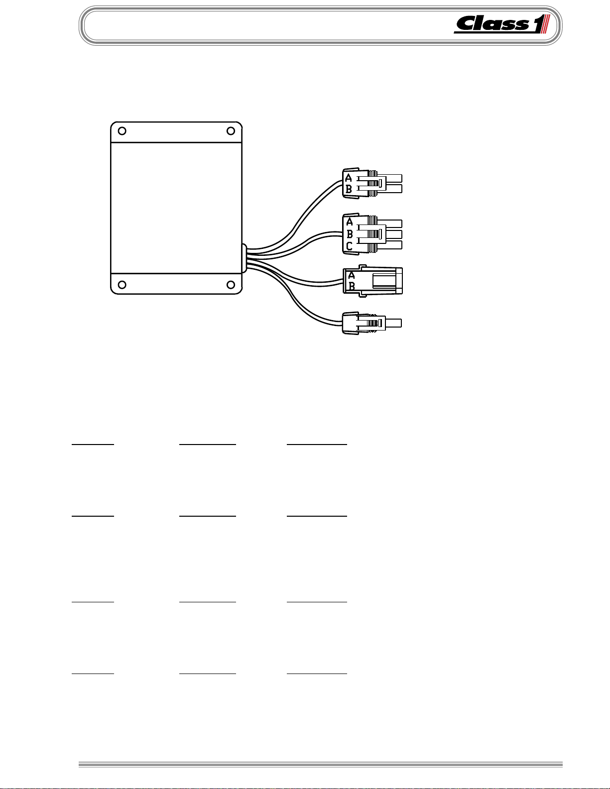
Connectors
Throttle Interface
C1 POWER SUPPLY
for
Cummins Engines
C2 THROTTLE INPUT
C3 DA TA LINK
C4 HIGH IDLE
Connector Information
C1 Connector 12015792 T erminal 12089188 Seal 12015899
Position Wire Color Description
A Red Throttle Interlock
B Black Ground
C2 Connector 12015793 T erminal 12089188 Seal 12015899
Position Wire Color Description
A White Throttle ground
B Blue Throttle Signal
C Orange Throttle Source
C3 Connector 12010973 T erminal 12089040 Seal 12015899
Position Wire Color Description
A Wht/Red Data A
B Wht/Black Data B
C4 Connector 12015791 T erminal 12089188 Seal 12015899
Position Wire Color Description
A Green Fast Idle*
* This input bypasses idle validation and allows the interface to command engine torque as
soon as power is applied.
DOC 101058C_c:\manuals\throttles\cummins\cumthrot.p65
5
Page 6
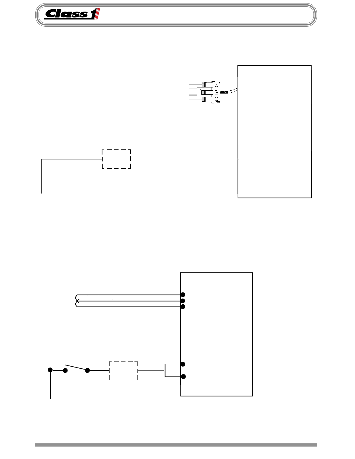
Wiring
Wiring the Class1 Vernier Throttle
VERNIER THROTTLE
PTO
OEM
Interlocks
12 VDC
manuals\throttles\cummins\cumvt.ai..042898
C2-B
Throttle Signal
Cummins Interface
C1-A
12 VDC
Wiring the Class1 Vernier Throttle with high idle option only
Class 1
12 VDC
6
HIGH IDLE POT
Fast Idle
Switch
C2-A Throttle Ground
C2-B Throttle Signal
C2-C Throttle Source
Class 1
Cummins Interface
OEM
Interlocks
FAST
IDLE
DOC 101058C_c:\manuals\throttles\cummins\cumthrot.p65
manuals\throttles\cummins\cumhigh.ai..042898
C1-A
12 VDC
C4
Page 7
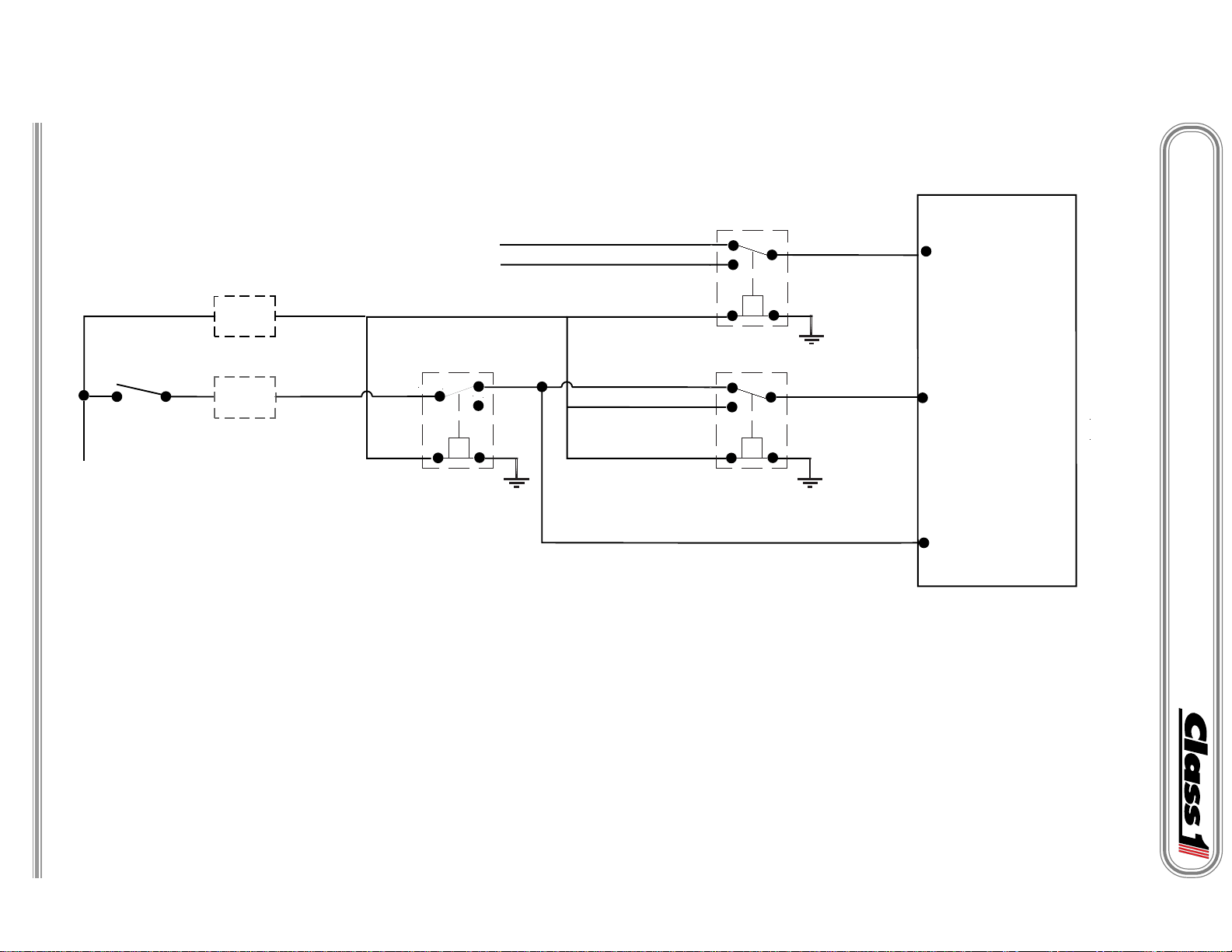
Wiring the Class1 Vernier Throttle with a remote high idle option
DOC 101058C_c:\manuals\throttles\cummins\cumthrot.p65
Fast Idle
Switch
12 VDC
5 VDC
SIGNAL
C2-C
C2-B
PTO
OEM
Interlocks
FAST
IDLE
VERNIER THROTTLE
HOOKED IN PARALLEL TO HIGH IDLE POT.
CONNECT TO VERNIER THROTTLE INPUT AT RELAY 1
85
30
Relay 3
HIGH IDLE POT
VERNIER THROTTLE
87a
87
86
FROM C2-C
CONNECT TO HIGH IDLE POT INPUT AT RELAY 1
HIGH IDLE POT.
87a
87
85
87a
87
85
Relay 1
Relay 2
86
86
30
30
C2-B
Throttle Signal
Class 1
Cummins Interface
C1-A
12 VDC
C4
Wiring
GROUND
7
C2-A
RELAY 3 DISABLES HIGH IDLE WHEN OK TO PUMP/PTO ENGAGED SIGNAL IS PRESENT
RELAY 2 SELECTS THE SOURCE OF THE INTERLOCK (HIGH IDLE OR PTO)
RELAY ONE SELECTS WHICH THROTTLE SIGNAL (HIGH IDLE OR VERNIER) IS DELIVERED TO THE INTERFACE MODULE
HOOKED IN PARALLEL TO HIGH IDLE POT.
FROM C2-A
manuals\throttles\cummins\cumvthi.ai..120996
Page 8

1.0"
3.000"
4.25"
4.75"
3.625"
Ø 0.201"
(4) HOLES
Mounting Template
Throttle Interface Module
Mounting
DOC 101058C_c:\manuals\throttles\cummins\cumthrot.p65
8
Page 9

Operation
When the throttle interface module is powered up by the safety (interlock) system the throttle
module will perform a self check and the LED on the module will turn on and then turn off after
the self check if everything passes. (approx. 4 secs)
After the self check, the interface will verify that the throttle is fully closed. If the throttle is not
fully closed, the LED on the interface module will flash once every 2 seconds until the zero
position is detected.
IMPORTANT
engine until the zero position is detected.
This feature is present to avoid unintentional increases in engine speed should the throttle be
left in the open position.
The fast idle input overrides this feature and should be used with caution.
After the interface module passes the self test and detects zero throttle, it is ready to control the
engine. The interface module controls the engine electronically by sending torque commands
to the Engine Control Module (ECM).
Once the throttle has been opened approximately 1/4 turn, the interface module will begin to
control the engine. The interface module will override the foot throttle in the cab. There will be
a short delay of 1-2 seconds when the interface module initially takes control from the foot
throttle. Once control is established, the throttle response will be immediate and precise. For
best operation, open the throtlle from 1/4 to 1/2 turn and wait until you hear or see the engine
RPM increase to 800. At this time the interface module is in control of the engine and normal
operation of the vernier throttle is supported from 800 to full engine speed.
When finished operating the remote throttle, the operator should return the throttle to idle and
turn the control to it’s full clockwise position. When the interface module detects this position,
and engine speed is at or below 800 RPM, it will release control to the foot throttle after 3-4
seconds.
The throttle interface module will not command increased torque from the
Each time the throttle is moved from idle or back to idle, the transfer of control takes place and
the operator should expect a short delay in control response at these times.
Note: When the throttle interface is not powered, it is physically disconnected from the engine
so that it cannot under any circumstance control engine speed or interfere with another engine
speed control.
For questions or concerns regarding the governor, call Class1 at 352-629-5020 or F AX 352-629-2902.
DOC 101058C_c:\manuals\throttles\cummins\cumthrot.p65
9
 Loading...