


FORM-ENG-0018 REV A 06-02-03
ISO 9001 CERTIFIED
607 NW 27th Ave
Ocala, FL 34475
Phone: (352) 629-5020 or 800-533-3569 Fax: (352)-629-2902
SUITABLE FOR EXTERNAL DISTRIBUTION
TECHNICAL PRODUCT DATASHEET
Total Pressure Governor Plus
TPG+
P/N 118710

FORM-ENG-0018 REV A 05-27-03
|
|
|
|
|
|
|
TECHNICAL DATA SHEET |
PAGE |
1 OF 30 |
|||
|
|
|
|
|
|
|
DATE |
4/9/2009 |
||||
|
|
607 NW 27th Ave |
|
|
PRODUCT GROUP |
THROTTLE CONTROL |
P/N |
118710 |
REV |
1.00 |
||
|
|
Ocala, FL 34475 |
|
|
||||||||
Ph: 352-629-5020 or 1-800-533-3569 |
|
TOTAL PRESSURE GOVERNOR PLUS (TPG+) |
|
|
||||||||
Fax : 352-629-2902 or 1-800-520-3473 |
PRODUCT |
BY |
AMS |
|||||||||
1. |
REVISION LOG ........................................................................................................................................... |
|
3 |
|||||||||
2. |
SYSTEM OVERVIEW .................................................................................................................................. |
|
4 |
|||||||||
|
|
2.1. |
SYSTEM PART NUMBERS ........................................................................................................................... |
|
4 |
|||||||
|
|
2.2. |
HARNESS DETAIL (P/N 118453 AND P/N 117683)....................................................................................... |
|
4 |
|||||||
3. |
OVERVIEW OF THE TOTAL PRESSURE GOVERNOR PLUS................................................................. |
|
6 |
|||||||||
|
|
3.1. |
INFO CENTER DISPLAY.............................................................................................................................. |
|
7 |
|||||||
|
|
3.2. |
INTERLOCK STATUS INDICATORS ............................................................................................................... |
|
7 |
|||||||
|
|
3.3. |
SWITCH PANEL ......................................................................................................................................... |
|
7 |
|||||||
|
|
3.3.1. |
|
IDLE................................................................................................................................................... |
|
7 |
||||||
|
|
3.3.2. |
|
MENU/SILENCE................................................................................................................................ |
|
7 |
||||||
|
|
3.3.3. |
|
PRESET ............................................................................................................................................ |
|
7 |
||||||
|
|
3.3.4. |
|
MODE................................................................................................................................................ |
|
7 |
||||||
|
|
3.3.5. |
|
INC..................................................................................................................................................... |
|
7 |
||||||
|
|
3.3.6. |
|
DEC ................................................................................................................................................... |
|
7 |
||||||
|
|
3.4. |
MODE INDICATOR ..................................................................................................................................... |
|
7 |
|||||||
|
|
3.5. |
ENGINE RPM DISPLAY.............................................................................................................................. |
|
7 |
|||||||
|
|
3.6. |
BATTERY VOLTAGE MONITOR .................................................................................................................... |
|
8 |
|||||||
|
|
3.7. |
COOLANT TEMPERATURE MONITOR ........................................................................................................... |
|
8 |
|||||||
|
|
3.8. |
OIL PRESSURE MONITOR........................................................................................................................... |
|
8 |
|||||||
|
|
3.9. |
PUMP INTAKE PRESSURE DISPLAY ............................................................................................................. |
|
8 |
|||||||
|
|
3.10. |
PUMP DISCHARGE PRESSURE DISPLAY ...................................................................................................... |
|
8 |
|||||||
|
|
3.11. |
STOP ENGINE AND CHECK ENGINE INDICATORS .......................................................................................... |
|
8 |
|||||||
4. |
OPERATION ................................................................................................................................................ |
|
9 |
|||||||||
|
|
4.1. |
INITIALIZATION.......................................................................................................................................... |
|
9 |
|||||||
|
|
4.2. |
OPERATING MODE SELECTION................................................................................................................. |
|
10 |
|||||||
|
|
4.2.1. |
|
Throttle mode .................................................................................................................................. |
|
10 |
||||||
|
|
4.2.2. |
|
Pressure mode ................................................................................................................................ |
|
11 |
||||||
|
|
4.3. |
REQUIRED INTERLOCKING....................................................................................................................... |
|
12 |
|||||||
|
|
4.4. |
PRESET SWITCH OPERATION................................................................................................................. |
|
12 |
|||||||
|
|
4.5. |
IDLE SWITCH OPERATION ....................................................................................................................... |
|
12 |
|||||||
|
|
4.6. |
MENU/SILENCE SWITCH OPERATION.................................................................................................... |
|
13 |
|||||||
|
|
4.6.1. Viewing the engine and pump related items ................................................................................... |
|
13 |
||||||||
|
|
4.6.2. |
|
Silencing the alarm.......................................................................................................................... |
|
14 |
||||||
|
|
4.7. |
STATUS AND WARNING MESSAGES .......................................................................................................... |
|
15 |
|||||||
|
|
4.8. |
AUTOMATIC DISPLAY BRIGHTNESS ........................................................................................................... |
|
16 |
|||||||
5. |
GOVERNOR CONTROL SETUP MENU................................................................................................... |
|
17 |
|||||||||
|
|
5.1. |
ENGINE COMPATIBILITY........................................................................................................................... |
|
17 |
|||||||
|
|
5.2. |
ENTER THE SETUP MENU ........................................................................................................................ |
|
17 |
|||||||
|
|
5.2.1. UNITS (unit of measure configuration)............................................................................................ |
|
20 |
||||||||
|
|
5.2.2. PRESET RPM (throttle preset configuration).................................................................................. |
|
20 |
||||||||
|
|
5.2.3. HI-IDLE (high idle configuration) ..................................................................................................... |
|
20 |
||||||||
|
|
5.2.4. PRESET PSI (pressure preset configuration) ................................................................................. |
|
20 |
||||||||
|
|
5.2.5. |
|
BRIGHT (display brightness)........................................................................................................... |
|
20 |
||||||
|
|
5.2.6. |
|
NIGHT (display brightness) ............................................................................................................. |
|
20 |
||||||
|
|
5.2.7. |
|
DISPLAY TEST ............................................................................................................................... |
|
20 |
||||||
|
|
5.2.8. |
|
ROUND PSI..................................................................................................................................... |
|
20 |
||||||
|
|
5.2.9. ALERT TONE (configure alert tones).............................................................................................. |
|
21 |
||||||||
|
|
5.2.10. |
|
SENSITIVITY (pressure sensitivity configuration) ...................................................................... |
|
21 |
||||||
Manual P/N 118711

FORM-ENG-0018 REV A 05-27-03
|
|
|
|
|
|
TECHNICAL DATA SHEET |
|
PAGE |
2 OF 30 |
|||
|
|
|
|
|
|
|
DATE |
4/9/2009 |
||||
|
607 NW 27th Ave |
|
|
PRODUCT GROUP |
THROTTLE CONTROL |
P/N |
118710 |
|
REV |
1.00 |
||
|
Ocala, FL 34475 |
|
|
|
||||||||
Ph: 352-629-5020 or 1-800-533-3569 |
|
TOTAL PRESSURE GOVERNOR PLUS (TPG+) |
|
|
|
|||||||
Fax : 352-629-2902 or 1-800-520-3473 |
PRODUCT |
|
BY |
AMS |
||||||||
5.2.11. |
|
SENSOR CAL (pressure sensor calibration) .............................................................................. |
|
21 |
||||||||
5.2.12. |
|
1st MODE (first active mode configuration) ................................................................................. |
|
21 |
||||||||
5.2.13. |
|
COMM STATUS (view the CAN communication status) ............................................................ |
|
21 |
||||||||
5.2.14. |
|
CONTROL (engine control message type) ................................................................................. |
|
21 |
||||||||
5.2.15. |
|
AUTO MODE (pressure mode automatically entered on pump engagement) |
........................... |
21 |
||||||||
5.2.16. |
|
IDLE STEPS ............................................................................................................................... |
|
22 |
||||||||
5.2.17. |
|
IDLE RPM ................................................................................................................................... |
|
22 |
||||||||
5.2.18. |
|
MAXIMUM RPM.......................................................................................................................... |
|
22 |
||||||||
5.2.19. |
|
SourceID (CAN message source identification).......................................................................... |
|
22 |
||||||||
5.2.20. |
|
PSI TIME-OUT (pressure time out)............................................................................................. |
|
22 |
||||||||
5.2.21. |
|
ALLOW PRESET (allow RPM preset use when pressure is detected) ...................................... |
|
22 |
||||||||
5.2.22. |
|
WARNINGS (data monitor warning configuration) ..................................................................... |
|
23 |
||||||||
|
|
A. |
WARN ºF (User defined engine temperature high warning - Yellow LED)...................................................... |
|
23 |
|||||||
|
|
B. |
CRIT ºF (User defined engine temperature high critical - Red LED) .............................................................. |
|
23 |
|||||||
|
|
C. |
WARN PSI (User defined oil pressure low warning - Yellow LED) ................................................................. |
|
23 |
|||||||
|
|
D. |
CRIT PSI (User defined oil pressure low critical - Red LED) .......................................................................... |
|
23 |
|||||||
5.2.23. |
|
XDUCR (discharge pressure transducer range)......................................................................... |
|
23 |
||||||||
5.2.24. |
|
FACTORY DFLT (Set factory defaults)....................................................................................... |
|
23 |
||||||||
5.2.25. |
|
GOV GAIN (RPM change per step) ............................................................................................ |
|
23 |
||||||||
5.2.26. |
|
PRESS GAIN (PSI change per step) .......................................................................................... |
|
23 |
||||||||
5.2.27. |
|
DITHER (Engine handshake)...................................................................................................... |
|
23 |
||||||||
5.2.28. |
|
LAG ∆PSI (Pressure lag) ............................................................................................................ |
|
24 |
||||||||
5.2.29. |
|
PUMP HOURS............................................................................................................................ |
|
24 |
||||||||
5.2.30. |
|
BCM1 VER (Body Control Message 1 version) .......................................................................... |
|
24 |
||||||||
5.2.31. |
|
SCANIA MODE? (Scania governor type) ................................................................................... |
|
24 |
||||||||
6. |
CONFIGURATION ..................................................................................................................................... |
|
25 |
|||||||||
6.1. |
CONFIGURE THE UNIT OF MEASURE ......................................................................................................... |
|
25 |
|||||||||
6.2. |
SELECT PRESSURE TRANSDUCER RANGE: 300 PSI (DEFAULT) OR 600 PSI ............................................... |
|
25 |
|||||||||
6.3. |
ZERO CALIBRATE THE INTAKE AND DISCHARGE PRESSURE TRANSDUCERS ................................................. |
|
26 |
|||||||||
6.4. |
CONFIGURE THE ENGINE CONTROL METHOD ............................................................................................ |
|
26 |
|||||||||
6.5. |
CONFIGURE THE IDLE VOLTAGE AND GAIN SETTING USING AUTO SCALE ................................................. |
|
27 |
|||||||||
7. |
MOUNTING & INSTALLATION................................................................................................................. |
|
28 |
|||||||||
7.1. |
PANEL CUTOUT DIMENSIONS ................................................................................................................... |
|
28 |
|||||||||
8. |
CONNECTOR DESCRIPTION................................................................................................................... |
|
29 |
|||||||||
8.1. |
TPG+ CONNECTORS .............................................................................................................................. |
|
29 |
|||||||||
8.2. |
PRESSURE SENSOR CONNECTOR ............................................................................................................ |
|
29 |
|||||||||
9. |
TECHNICAL DETAILS .............................................................................................................................. |
|
30 |
|||||||||
Manual P/N 118711
FORM-ENG-0018 REV A 05-27-03
|
|
|
|
TECHNICAL DATA SHEET |
PAGE |
3 OF 30 |
|||
|
|
|
|
DATE |
4/9/2009 |
||||
|
607 NW 27th Ave |
PRODUCT GROUP |
THROTTLE CONTROL |
P/N |
118710 |
REV |
1.00 |
||
|
Ocala, FL 34475 |
||||||||
Ph: 352-629-5020 or 1-800-533-3569 |
|
TOTAL PRESSURE GOVERNOR PLUS (TPG+) |
|
|
|||||
Fax : 352-629-2902 or 1-800-520-3473 |
PRODUCT |
BY |
AMS |
||||||
|
|
|
|
|
|
|
|
|
|
1. Revision Log
Rev |
Date |
Changes |
1.00 |
4/9/2009 |
Initial revision |
Product specifications in this manual are subject to change without notice.
Manual P/N 118711
FORM-ENG-0018 REV A 05-27-03
|
|
|
|
|
|
|
TECHNICAL DATA SHEET |
PAGE |
4 OF 30 |
|
||||
|
|
|
|
|
|
|
DATE |
4/9/2009 |
|
|||||
|
|
607 NW 27th Ave |
|
PRODUCT GROUP |
THROTTLE CONTROL |
P/N |
118710 |
REV |
1.00 |
|
||||
|
|
Ocala, FL 34475 |
|
|
||||||||||
Ph: 352-629-5020 or 1-800-533-3569 |
|
|
TOTAL PRESSURE GOVERNOR PLUS (TPG+) |
|
|
|
||||||||
Fax : 352-629-2902 or 1-800-520-3473 |
|
PRODUCT |
BY |
AMS |
|
|||||||||
|
|
|
|
|
|
|
|
|
||||||
2. |
System Overview |
|
|
|
|
|
|
|||||||
2.1. |
System part numbers |
|
|
|
|
|
|
|||||||
|
|
|
Total Pressure Governor Plus (TPG+) system kit |
119650 |
|
|
|
|||||||
|
|
|
Kit includes |
|
|
|
|
|
|
|
|
|
||
|
|
|
Total Pressure Governor Plus (TPG+) |
QTY-1 |
118710 |
|
|
|
||||||
|
|
|
TPG+ main system harness |
QTY-1 |
118453 |
|
|
|
||||||
|
|
|
Transducer 0-300 PSI |
QTY-2 |
113557 |
|
|
|
||||||
|
|
|
Optional items |
|
|
|
|
|
|
|||||
|
|
|
TPG+ analog signal harness (analog control option) |
117683 |
|
|
|
|||||||
|
|
|
Transducer 0-600 PSI |
|
|
117179 |
|
|
|
|||||
|
|
|
Documentation (available from Class 1’s website - www.class1.com) |
|
|
|
||||||||
|
|
|
TPG+ system Manual (this manual) |
|
|
118711 |
|
|
|
|||||
|
|
|
TPG+ OEM Quick Manual |
|
|
118712 |
|
|
|
|||||
|
|
|
Engine compatibility guide |
|
|
117686 |
|
|
|
|||||
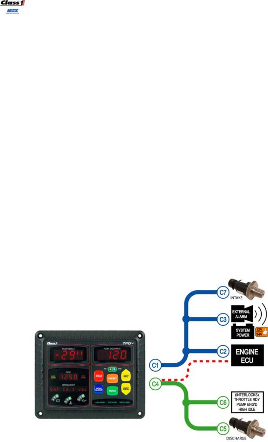
2.2.Harness detail (p/n 118453 and p/n 117683)
The main system harness (p/n 118453) is comprised of a pair of harnesses: the power/communication harness (depicted below in blue) and the signals harness (depicted below in green).
When the analog signal control option is desired instead of the standard CAN control option then the analog control option harness is also required (p/n 117683). This harness is actually a set of wires and sockets which must be inserted into connector C4 (depicted below with a red dashed line).
Figure 1. Harness nomenclature.
Manual P/N 118711
FORM-ENG-0018 REV A 05-27-03
|
|
|
|
TECHNICAL DATA SHEET |
PAGE |
5 OF 30 |
|||
|
|
|
|
DATE |
4/9/2009 |
||||
|
607 NW 27th Ave |
PRODUCT GROUP |
THROTTLE CONTROL |
P/N |
118710 |
REV |
1.00 |
||
|
Ocala, FL 34475 |
||||||||
Ph: 352-629-5020 or 1-800-533-3569 |
|
TOTAL PRESSURE GOVERNOR PLUS (TPG+) |
|
|
|||||
Fax : 352-629-2902 or 1-800-520-3473 |
PRODUCT |
BY |
AMS |
||||||
|
|
|
|
|
|
|
|
|
|
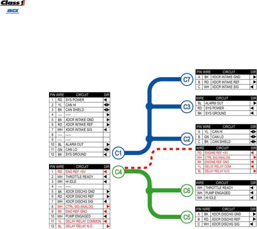
Figure 2. Harness wiring detail - p/n 118453 with analog option harness p/n 117683 (red).
Manual P/N 118711
FORM-ENG-0018 REV A 05-27-03
|
|
|
|
TECHNICAL DATA SHEET |
PAGE |
6 OF 30 |
|||
|
|
|
|
DATE |
4/9/2009 |
||||
|
607 NW 27th Ave |
PRODUCT GROUP |
THROTTLE CONTROL |
P/N |
118710 |
REV |
1.00 |
||
|
Ocala, FL 34475 |
||||||||
Ph: 352-629-5020 or 1-800-533-3569 |
|
TOTAL PRESSURE GOVERNOR PLUS (TPG+) |
|
|
|||||
Fax : 352-629-2902 or 1-800-520-3473 |
PRODUCT |
BY |
AMS |
||||||
|
|
|
|
|
|
|
|
|
|
3. Overview of the Total Pressure Governor Plus
The Total Pressure Governor Plus (TPG+) p/n 118710 is an SAE J1939 Controller Area Network (CAN) device that controls engine speed using data communications directly to the engine ECU or through with an analog control signal. By operating on the J1939 network, the governor is able to monitor engine RPM and other pertinent data directly from the engine ECU. Engine information is available directly so that NFPA required instrumentation is delivered through a single unit saving panel space and delivering engine specific warnings as determined by each engine manufacturer.
Control algorithms are optimized to take advantage of the J1939 CAN data to yield crisp and accurate control of engine and subsequently pump speed and pressure output.
For engines that may not support the data link control, an analog output signal is available to provide precise control of the engine speed and pressure.
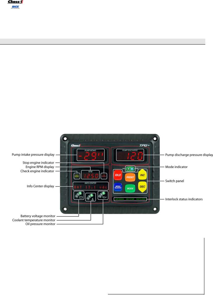
The TPG+ saves pump panel space by incorporating easy to read numeric displays for Pump Intake pressure, Pump Discharge pressure, and engine RPM in accordance with NFPA standards.
|
Figure 3. TPG+ controls and indicators. |
|
|
|
|
|
|
Pump intake pressure display |
section 3.9 |
Pump discharge pressure display |
section 3.10 |
Stop engine indicator |
section 3.11 |
Mode indicator |
section 3.4 |
Engine RPM display |
section 3.5 |
Switch panel |
section 3.3 |
Check engine indicator |
section 3.11 |
Idle |
section 3.3.1 |
Info Center display |
section 3.1 |
Menu/Silence |
section 3.3.2 |
Battery voltage monitor |
section 3.6 |
Preset |
section 3.3.3 |
Coolant temperature monitor |
section 3.7 |
Mode |
section 3.3.4 |
Oil pressure monitor |
section 3.8 |
Inc |
section 3.3.5 |
|
|
Dec |
section 3.3.6 |
|
|
Interlock status indicators |
section 3.2 |
|
|
|
|
Manual P/N 118711

FORM-ENG-0018 REV A 05-27-03
|
|
|
|
TECHNICAL DATA SHEET |
PAGE |
7 OF 30 |
|||
|
|
|
|
DATE |
4/9/2009 |
||||
|
607 NW 27th Ave |
PRODUCT GROUP |
THROTTLE CONTROL |
P/N |
118710 |
REV |
1.00 |
||
|
Ocala, FL 34475 |
||||||||
Ph: 352-629-5020 or 1-800-533-3569 |
|
TOTAL PRESSURE GOVERNOR PLUS (TPG+) |
|
|
|||||
Fax : 352-629-2902 or 1-800-520-3473 |
PRODUCT |
BY |
AMS |
||||||
|
|
|
|
|
|
|
|
|
|
3.1.Info Center display
The display shows status, warning, and information messages.
3.2.Interlock status indicators
Backlit text indicates the status of the three (3) interlocks: pump engaged, okay to pump, and throttle ready. Throttle ready and pump engaged are physical inputs into the gray 12-pin connector (pins 2 and 10 respectively) of the TPG+. Okay to pump becomes active when both the throttle ready and pump engaged interlocks are present.
3.3.Switch panel
The six (6) control switches are color coded and labeled for easy identification.
3.3.1.IDLE
The IDLE switch (red) forces the governor to idle mode (standby). Pressing and holding this button for one second while in rpm or pressure mode will cause the engine to ramp down to its idle position.
3.3.2.MENU/SILENCE
The MENU/SILENCE switch (blue) is used to silence the alarm, cycle through the display items, and enter the setup menu.
3.3.3.PRESET
The PRESET switch (orange) sets the governor to the configured preset engine RPM while in throttle mode, or preset pressure while in pressure mode.
3.3.4.MODE
The MODE switch (green) sets the governor to either throttle mode (RPM) or pressure mode (PSI). The correct interlocks must be present for the system to begin governor operation: throttle ready for RPM mode, throttle ready, pump engaged, and okay to pump for PSI mode.
3.3.5.INC
The INC [increase] switch (yellow) is used to increase the engine RPM or pressure set point.
3.3.6.DEC
The DEC [decrease] switch (yellow) is used to decrease the engine RPM or pressure set point.
3.4.Mode indicator
The mode indicator consists of two (2) LEDs to show the governor’s current operating mode. The PSI LED (yellow) indicates the governor is operating in pressure mode and the RPM LED (blue) indicates the governor is operating in throttle mode. When both LEDs are OFF the governor is in idle mode (standby).
3.5.Engine RPM display
The engine RPM display shows the current engine RPM as reported by the Electronic Engine Controller 1 (EEC1) SAE J1939 network data message transmitted by the vehicle ECU.
Manual P/N 118711

FORM-ENG-0018 REV A 05-27-03
|
|
|
|
TECHNICAL DATA SHEET |
PAGE |
8 OF 30 |
|||
|
|
|
|
DATE |
4/9/2009 |
||||
|
607 NW 27th Ave |
PRODUCT GROUP |
THROTTLE CONTROL |
P/N |
118710 |
REV |
1.00 |
||
|
Ocala, FL 34475 |
||||||||
Ph: 352-629-5020 or 1-800-533-3569 |
|
TOTAL PRESSURE GOVERNOR PLUS (TPG+) |
|
|
|||||
Fax : 352-629-2902 or 1-800-520-3473 |
PRODUCT |
BY |
AMS |
||||||
|
|
|
|
|
|
|
|
|
|
3.6.Battery voltage monitor
The battery voltage monitor is comprised of three (3) LEDs (green, yellow, and red). The active LED color indicates the current system voltage’s range as measured by the power and ground inputs pins. The alarm will activate when the voltage monitor is in condition RED.
• |
GREEN |
12.5VDC and higher |
• |
YELLOW |
12.4VDC to 11.9VDC |
• |
RED |
11.8VDC and lower |
3.7.Coolant temperature monitor
The coolant temperature monitor is comprised of three (3) LEDs (green, yellow, and red). The active LED color indicates the status of the coolant temperature as reported by the Diagnostic Message 1 (DM1) SAE J1939 network data message transmitted by the vehicle ECU. The coolant temperature status can also be set to react to user desired points (see section 5.2.22). The alarm will activate when the coolant temperature monitor is in condition RED.
• |
GREEN |
No active error reported by engine for coolant temperature |
• |
YELLOW |
Coolant temperature high WARNING – SPN 110, FMI 16 |
• |
RED |
Coolant temperature high CRITICAL – SPN 110, FMI 0 |
3.8.Oil pressure monitor
The oil pressure monitor is comprised of three (3) LEDs (green, yellow, and red). The active LED color indicates the status of the oil pressure as reported by the Diagnostic Message 1 (DM1) SAE J1939 network data message transmitted by the vehicle ECU. The oil pressure status can also be set to react to user desired points (see section 5.2.22). The alarm will activate when the oil monitor is in condition RED.
• |
GREEN |
No active error reported by engine for oil pressure |
• |
YELLOW |
Oil pressure low WARNING – SPN 100, FMI 18 |
• |
RED |
Oil pressure low CRITICAL – SPN 100, FMI 1 |
3.9.Pump intake pressure display
The pump intake pressure display shows the pressure as determined by the intake pressure sensor. By default, this display shows positive pressure in pounds per square inch (PSI) and negative pressure (vacuum) in inches of mercury (inHg), but it may be set up to display in metric units (see section 6.1).
3.10.Pump discharge pressure display
The pump discharge pressure display shows the pressure as determined by the discharge pressure sensor. By default, this display only shows positive pressure in pounds per square inch (PSI), but it may be set up to display in metric units (see section 6.1).
3.11.Stop engine and check engine indicators
The stop engine and check engine indicators are turned ON and OFF as directed by the Diagnostic Message 1 (DM1) SAE J1939 network data message transmitted by the vehicle ECU.
Manual P/N 118711

FORM-ENG-0018 REV A 05-27-03
|
|
|
|
TECHNICAL DATA SHEET |
PAGE |
9 OF 30 |
|||
|
|
|
|
DATE |
4/9/2009 |
||||
|
607 NW 27th Ave |
PRODUCT GROUP |
THROTTLE CONTROL |
P/N |
118710 |
REV |
1.00 |
||
|
Ocala, FL 34475 |
||||||||
Ph: 352-629-5020 or 1-800-533-3569 |
|
TOTAL PRESSURE GOVERNOR PLUS (TPG+) |
|
|
|||||
Fax : 352-629-2902 or 1-800-520-3473 |
PRODUCT |
BY |
AMS |
||||||
|
|
|
|
|
|
|
|
|
|
4. Operation
4.1.Initialization
The TPG+ has a six (6) second power initialization cycle and during this time the display will show:
First second after the power on cycle.
The TPG+ lights all indicators and shows “8.8.8.8. “ in the pump intake, pump discharge, and RPM display windows.
The Info Center shows “Class 1 TPG-X”. The last letter of this display indicates the configured control method of the TPG+.
TPG-C – CFPG control method
TPG-P – PGN0 control method
TPG-A – Analog control method
TPG-S – Scania control method
(See section 6.4 for engine configuration).
Seconds 2 through 4 after the power on cycle.
The TPG+ continues to light all indicators and shows “8.8.8.8. “ in the pump intake, pump discharge, and RPM display windows.
The Info Center shows the software version of the TPG+.
The final two seconds after the power on cycle.
The TPG+ turns off all of the indicators and lights only the decimals of the pump intake, pump discharge, and RPM display windows.
The Info Center shows “Initializing”.
After the initialization the TPG+ begins normal operation.
Manual P/N 118711
 Loading...