

Page 1
Class 1, Inc. • A Unit of IDEX Corporation
www.class1.com
Class 1
Valve
manual
607 NW 27th Avenue • OCALA, FL 34475 USA
800.533.3569 • FAX: 352.629.2902
Class 1 Manual p/n 119138 – 04/14/10
Page 2

Class 1 Valve Manual
Table of Contents
1. Introduction & Specifications .................................................................................................... 3
2. Ball Valve Identification ............................................................................................................... 4
3. Ball Valve Actuators .................................................................................................................... 5
i. Remote Handle
ii. Direct Handle
iii. Rack Linkage
iv. Electric
4. Safety Information ........................................................................................................................ 9
5. Installation .................................................................................................................................... 11
i. Principles of Operation
ii. Installation Guidelines
iii. Direct and Remote Handle Installation
iv. Electric Actuator Installation
v. Slow Close Assembly Installation
vi. Rack Linkage Installation
6. Maintenance ................................................................................................................................ 23
i. After Each Use
ii. Monthly
iii. Valve Exploded Parts List
iv. Valve Repair Kits
7. Troubleshooting ......................................................................................................................... 26
2
p/n: 119138
Page 3

Class 1 Valve Manual
1. Introduction & Specifications
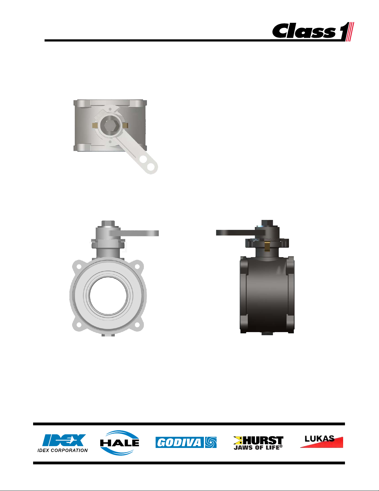
The new Class 1 four-piece stainless steel ball valves were created for reliability, corrosion resistance,
customization, and ease of maintenance.
Class 1 Stainless Steel Ball Valve
• The Class 1 stainless steel ball valves are available in 2.0”, 2.5”, and 3.0” sizes.
• Ball valves are composed of four main components: valve body assembly, inlet and discharge flange
adapters, and actuator.
• The center bodies are constructed of 304 stainless steel, and the balls are machined from 304
stainless steel.
• The stainless steel ball valves are bi-directional.
• The stainless steel ball valves use a single-piece seat and seal.
• A wide variety of 304 stainless steel valve end flanges are available to meet most of your plumbing
connection needs.
• Removing three of the four bolts on both flanges allows the valve to swing away from the plumbing,
and provide access to the waterway.
• For each valve size, the same stem geometry is used for all actuation options, eliminating the need
to change or remove the stem. For many options, only one bolt is required to add or remove a
valve handle.
• All valves are designed to meet or exceed NFPA 1901 standards.
3
p/n: 119138
Page 4
Class 1 Valve Manual
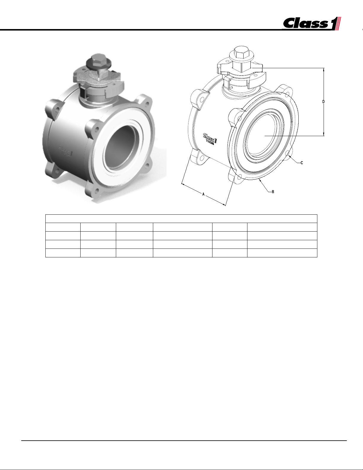
Center Body Assembly Dimensions
Size A B C D
Cast Body Part #
2.0”
3.00”
4.50”
3/8-16 Threads
3.44”
116237
2.5”
3.50”
5.375”
3/8-16 Threads
3.70”
116238
3.0”
3.98”
6.115”
3/8-16 Threads
4.08”
116239
2. Ball Valve Identification
Class 1 Stainless Steel Ball Valve – Center Body Assembly
A = width, valve center body; B = bolt circle; C = mounting threads; D = height, valve centerline to top of stop plate
4
p/n: 119138
Page 5
Class 1 Valve Manual
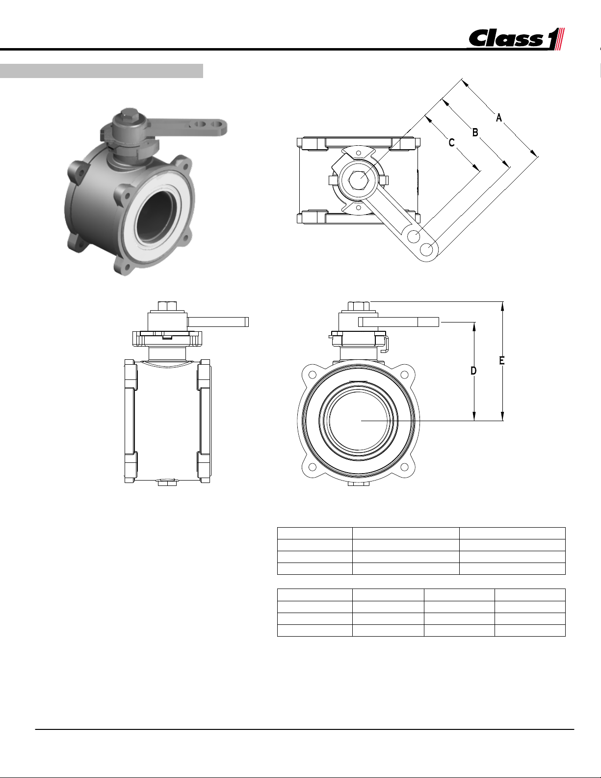
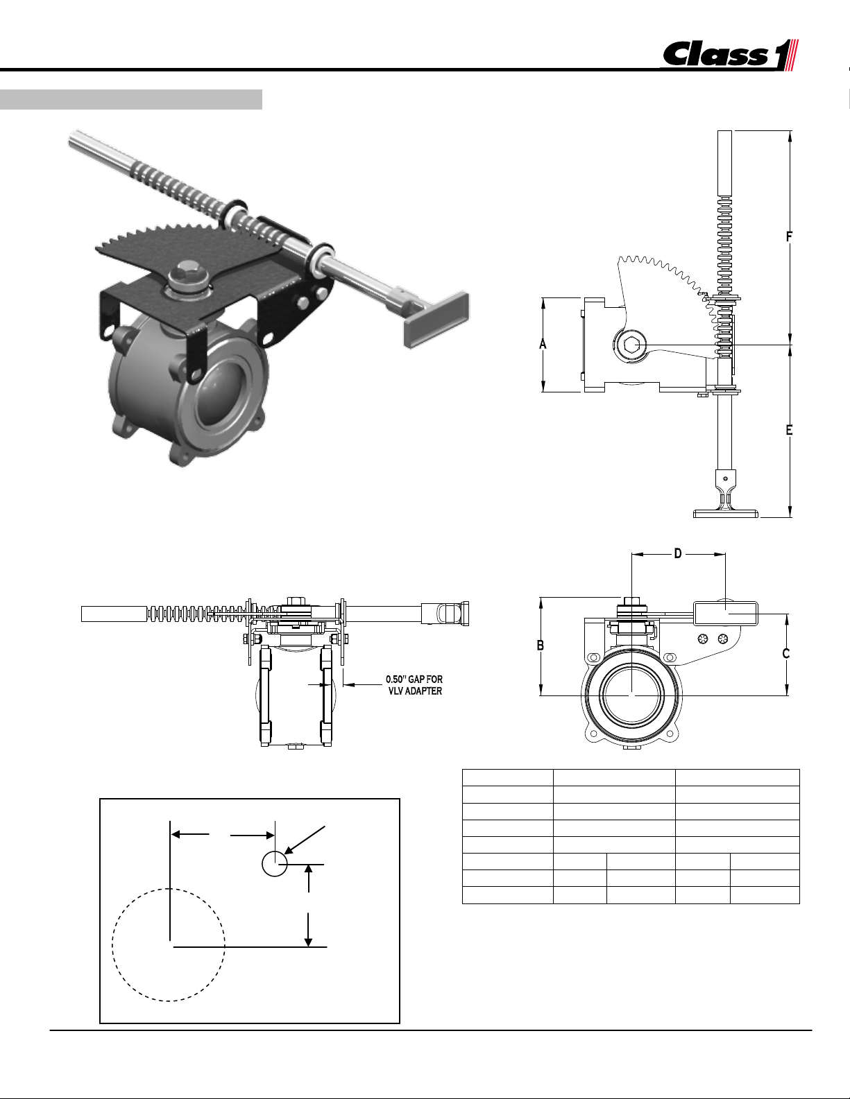
3.1 REMOTE HANDLE
Dimensions
Short Lever
Long Lever
A
4.50”
6.63”
B
4.00”
6.13”
C
3.25”
4.00”
Dimensions
2.0” Valve
2.5” Valve
3.0” Valve
D
3.82”
4.08”
4.46”
E
4.65”
4.91”
5.29”
F
5.30”
5.56”
5.94”
A = valve center to handle length;
3. Actuators
(115164)
B = valve center to outside hole;
C = valve center inside hole;
D = valve center to handle centerline;
E = valve center to top of assembly;
F = valve center to top of slow close
assembly (not shown)
5
p/n: 119138
(116303)
Page 6
Class 1 Valve Manual
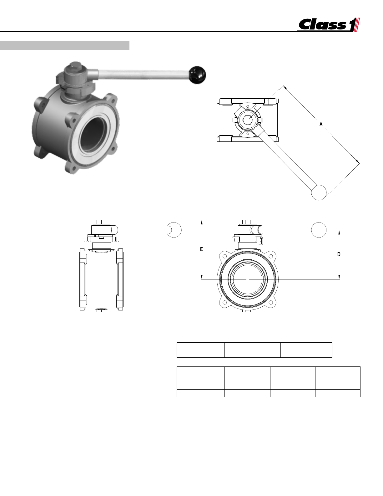
Dimensions
Short Handle
Long Handle
A
9.00”
9.50”
Dimensions
2.0” Valve
2.5” Valve
3.0” Valve
D
3.82”
4.08”
4.46”
E
4.65”
4.91”
5.29”
F
5.30”
5.56”
5.94”
A = valve center to handle length;
3. Actuators
3.2 DIRECT HANDLE
D = valve center to handle centerline;
E = valve center to top of assembly;
F = valve center to top of slow close
assembly (not shown)
[Use shim 119260 with all direct handle actuators. See Section 6.3 on page 24 for installation details.]
6
p/n: 119138
Page 7
Class 1 Valve Manual
Dimensions
2.5” Valve
3.0” Valve
A
4.75”
5.25”
B
4.90”
5.28”
C
4.094”
4.469”
D
4.675”
4.675”
E
15.40”
8.63”
15.40”
8.63”
F
3.93”
10.70”
3.93”
10.70”
3. Actuators
A = width of bracket;
Valve Center
D
Ø1.00”
C
Rod/Handle Cut-Out
3.3 RACK LINKAGE
7
p/n: 119138
OPEN CLOSED OPEN CLOSED
B = valve center to top of assembly;
C = valve center to handle centerline (height);
D = valve center to handle centerline (offset);
E = valve center to front of handle;
F = valve center to back of rod
Page 8
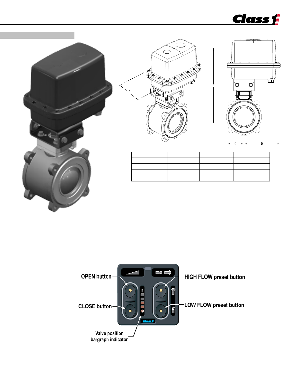
Class 1 Valve Manual
Dimensions
2.0” Valve
2.5” Valve
3.0” Valve
C
2.10”
2.43”
2.43”
D
4.35”
5.23”
5.23”
3. Actuators
A = width of actuator;
3.4 ELECTRIC
Electric actuators require Class 1 controller 117010 to operate.
The 117010 smart switch uses position feedback from the actuator to display
the valve’s open/close position. The smart switch can also be field programmed
for both high- and low-flow preset valve positions.
A 4.29” 5.16” 5.16”
B 9.32” 11.20” 11.58”
B = valve center to top of assembly;
C = valve center to actuator short side (length);
D = valve center to actuator long side (length)
117010 Smart Switch
8
p/n: 119138
Page 9
Class 1 Valve Manual
4. Safety Information
!
!
The Class 1 ball valves are designed for optimum safety of its
operators. For added protection, please follow the safety guidelines
listed in this section and adhere to all warning, danger, caution, and
important notes found within this manual.
The following section must be carefully read, understood, and
followed by all installers and operators before attempting to install or
operate Class 1 Valves. Failure to follow the installation and
maintenance requirements discussed below may result in serious
personal injury and/or damage to equipment.
When developing departmental apparatus operating procedures,
incorporate the warnings and cautions as written herein.
• READ ALL INSTRUCTIONS THOROUGHLY BEFORE BEGINNING ANY
INSTALLATION OR SERVICE PROCESS.
• Use care when removing the Class 1 valve from its packaging to prevent personal injury
and/or damage to the unit.
o The weight of the Class 1 ball valves varies according to size. Check your bill of
lading for the approximate weight. Where deemed necessary, be certain to use
proper lifting support devices or additional personnel.
• Before beginning any inspection, installation, maintenance, or service of any kind on the
valves, verify that the pressure has been released from the system. Lock out the equipment
in the system in accordance with the manufacturer’s recommendations.
• Installation should be performed by a trained and qualified installer. Be sure the installer has
sufficient knowledge, experience, and proper tools before attempting any installation.
o The installer is responsible for observing all instructions and safety precautions in his
or her daily routine as dictated by regional safety ordinances or departmental
procedures.
• DO NOT tamper with or disconnect safety features which could affect safe operation of
the valve and/or cause personal injury.
• Do not weld in proximity to the valve. Heat transfer from the welding process will damage
the plastic valve seals.
• No modifications or additions may be made to the Class 1 valve without prior written
permission from:
Class 1, Inc.
607 NW 27th Avenue
Ocala, FL 34475 USA
Telephone: (352) 629-5020
Fax: (352) 629-2902
• Disconnect all power sources before servicing an electric valve.
o Electrical systems have the potential to cause sparks during service or repair.
Eliminate explosive or hazardous materials in the environment during installation or
service.
9
p/n: 119138
Page 10

Class 1 Valve Manual
MODEL
RATED OPERATING PRESSURE
C20 (2.0”)
400 psi (1724 kPa)
C25 (2.5”)
400 psi (1724 kPa)
C30 (3.0”)
400 psi (1724 kPa)
4. Safety Information
o Electric motors and wiring are protected by a circuit breaker. DO NOT remove or
bypass the circuit breaker, as severe damage to the electric motor or apparatus
wiring could occur.
• Be careful that NO part of your body (head, feet, arms, legs, fingers, hair, etc.) is in an area
of rotating or moving parts.
• Certain internal parts of the Class 1 valve assembly may be under tension. When servicing
the valve, wear eye protection and exercise care when removing these parts.
• Fasteners used for the assembly of the Class 1 valves are plated Grade 8 steel.
• Foreign materials, like metal chips or shavings, can destroy the plastic seals on the valves.
Machine connected parts and remove foreign materials prior to installing the Class 1 valve.
• If your Class 1 valve includes the Slow-Close option, do not tamper with the slow-close
actuator. There are no serviceable parts inside. The actuator must never be disassembled.
Contact Class 1 for a replacement assembly.
o Current NFPA 1901 Standards specify that a minimum of three seconds is required
to open or close a 3” or larger valve.
• DO NOT exceed the rated Class 1 valve operating pressure, shown below:
10
p/n: 119138
Page 11

Class 1 Valve Manual
5. installation
Evaluate the best location for the valve installation, taking the following into consideration:
• Customer requirements
• Discharge location on the vehicle
• Maintenance accessibility
• Linkage Geometry – Refer to Hale Products service bulletin SB92 for details.
• Valve actuation
o Manual – left or right close; actuator position: left, right, top, or bottom; push rod or
handwheel
o Electric – wiring path; securing wire harness and mounting the controls
o Clearance around the actuator
• Control panel layout
5.1 Principals of Operation
• The Class 1 ball valve controls flow with a stainless steel internal ball. The valve uses a quarter-
turn design to minimize travel and is operated by manual lever, remote push rod, electric actuator,
or gear-driven actuator.
• The “swing out for service” design allows for watertight operation that is easy to use and easy to
maintain.
5.2 Installation Guidelines
• Pump body and compartment – Examine the pump body and the available space inside the pump
compartment to decide the best pump discharge opening to use. Account for space restrictions
from piping and valve control linkages throughout the compartment.
• Fasteners – Verify that all fasteners used on Class 1 valves are plated Grade 8 steel. Apply Loctite
#242 or equivalent to any threaded fasteners used to install an inlet or outlet valve adapter. Install
and tighten fasteners in a cross pattern, to ensure an even, watertight seal between the valve and
adapter. Torque the fasteners to a maximum 45 ft-lbs (Grade 8). [Refer to Hale Products
document ES018-002 – Torque Values for Threaded Fasteners, for more details.]
• NPT fittings – Use a joint sealing compound (Loctite or equivalent) on all NPT threaded adapter
fittings.
• Victaulic® connection – If the valve outlet adapter uses a Victaulic® fitting, connect the appropriate
coupling seal with a Victaulic® approved lubricant. Follow the recommended Victaulic® installation
procedures.
11
p/n: 119138
Page 12

Class 1 Valve Manual
Hex bolt & washer
5. installation
!
!
• Electric actuators – If an electric actuator is used, route the wire harness away from potentially hot
and/or moving parts. Secure the harness every 10” – 12” (254mm – 309mm) to prevent excessive
movement.
• Testing – After installation, verify that the valve cycles properly from fully OPENED to fully
CLOSED without excessive effort. If equipped with a hand wheel or electric control, verify that
the indicator lights sequence properly, indicating valve OPEN, CLOSE, or in between. Pressure
test valve connections before placing apparatus into service.
5.3 Direct and Remote Handle Installation
1. Remove the hex bolt and washer from the valve stem.
2. Slide the handle over the valve stem, so that it is seated on top of the stop plate.
3. As needed, adjust the handle and stop plate orientation so that the valve is open or closed with the
correct handle position.
4. Apply Loctite #242 or equivalent to the hex bolt and reinstall the bolt and washer to secure the
handle. Torque the bolt to 40 ft-lbs. [As the screw is tightened, ensure that the valve retaining bracket
is aligned so that it slides into the grooves on the valve body.]
5. Open and close the valve several times to check for smooth operation.
IMPORTANT
Retaining bracket seated in
groove (both sides) – Step 4
Handle
Stop plate
12
p/n: 119138
Page 13

Class 1 Valve Manual
Pins flush
with flat side
Bracket Base
Lower Bracket
Shims
Bottom
Plates
Actuator
Stem Adapter
5. installation
5.4 Electric Actuator Installation
5.4-1 Electric Actuator Assembly Parts 5.4-2 Valve with Stem and Insulator in Place
1. Remove the hex bolt and washer from the valve stem. (These are no longer needed.) Also
remove the stop plate, valve stem retainer (bend if necessary), and wave spring (see valve exploded
view for part details—Section 6.3). Keep the valve stem and valve stem insulator bushing in place.
[Figure 5.4-2]
2. Press the two (2) small dowel pins into the bracket base [Figure 5.4-3], so that they are flush with
the flat side.
3. Place the bracket base onto the top of the valve, aligning the dowel pins with the holes on the
valve. [Figure 5.4-4]
5.4-3 Bracket Base with Dowel Pins 5.4-4 Bracket Base Mounted onto Valve
4. Place the lower bracket on the bracket base. (Orientation of the bracket base affects the orientation of
the electric actuator, and must be determined by the installer.) Insert the four (4) long bolts through
the lower bracket and bracket base. [Figure 5.4-5]
13
p/n: 119138
Page 14

Class 1 Valve Manual
5. installation 5. installation
Incorrect Orientation –
5. Add the bottom plates and thread the long bolts into the plates. (Loctite use is recommended.)
Orient the bottom plates so that the ridges face down, toward the valve body. Torque four bolts
in a criss-cross pattern to a maximum value of 11 ft-lbs. (Discard shims – they are not needed.)
[Figures 5.4-6 through 5.4-8]
Figure 5.4-5 Lower Bracket with Four Long Bolts Figure 5.4-6 Adding the Bottom Plates
Ridge must face DOWN,
toward valve body
Figure 5.4-7 Fastening the Bottom Plates Figure 5.4-8 Incorrect Orientation of Bottom Plates
6. Install the valve stem adapter onto the valve stem. [Figure 5.4-9]
7. Attach the upper bracket and actuator to the lower bracket, using the three smaller hex bolts and
nuts. (You may have to rotate the valve stem to allow the adapter to sit correctly. Loctite use is
recommended.) [Figure 5.4-10]
8. Connect all wiring and harnesses.
9. Using the smart switch panel, open and close the valve a few times to ensure it is working properly.
Check the lights on the smart switch to verify that the ball is in the OPEN/CLOSE position as
indicated. If the OPEN switch closes the valve, remove the actuator, rotate the valve stem and ball
90°, and reattach the electric actuator.
14
p/n: 119138
Page 15

Class 1 Valve Manual
5. installation
Figure 5.4-9 Valve Stem Adapter Installed
Figure 5.4-10 Upper Bracket & Actuator Connected to Lower Bracket
15
p/n: 119138
Page 16

Class 1 Valve Manual
Bottom Plate
Base Bracket
Upper Bracket
Short Bolts &
Nuts
Bottom Bracket
Long Bolts
5. installation
& Actuator
Figure 5.4-11 Complete Installation of Electric Actuator
16
p/n: 119138
Page 17

Class 1 Valve Manual
5. installation
5.4.1 Utilizing the KZCO EH2 Series Electric Actuator (for 2.0” Class1 Valves)
The diagram below shows the typical layout using the SPS Electric Valve controller (117010) with KZCO
EH2 series electrical actuator (p/n 117234-003). The harness part number is 117593-XX (where XX is
the length in feet – 05, 10, 15, 20, 25, 30).
Harness p/n 117593-XX
(where XX is the length in feet – 05, 10, 15, 20, 25, 30).
KZCO EH2 series electrical actuator positioning details
Opening: positive polarity on pin B (white wire), ground polarity on pin A (green wire).
Valve moves in counter-clockwise direction (as viewed from top).
Fully open, voltage feedback = 2.80V (± 0.25V).
Closing: positive polarity on pin A (green wire), ground polarity on pin B (white wire).
Valve moves in clockwise direction (as viewed from top).
Fully closed, voltage feedback = 1.00V (± 0.25V).
17
p/n: 119138
Page 18

Class 1 Valve Manual
5. installation
5.4.2 Utilizing the KZCO EH5 Series Electric Actuator (for 2.5” & 3.0” Class1 Valves)
The diagram below shows the typical layout using the SPS Electric Valve controller (117010) with KZCO
EH5 series electrical actuator (p/n 117234). The harness part number is 117008-XX (where XX is the
length in feet – 05, 10, 15, 20, 25, 30).
Harness p/n 117008-XX
(where XX is the length in feet – 05, 10, 15, 20, 25, 30).
KZCO EH5 series electrical actuator positioning details
Opening: positive polarity on pin 3 (white wire).
Valve moves in counter-clockwise direction (as viewed from top).
Fully open, voltage feedback = 2.80V (± 0.25V).
Closing: positive polarity on pin 2 (green wire).
Valve moves in clockwise direction (as viewed from top).
Fully closed, voltage feedback = 1.00V (± 0.25V).
18
p/n: 119138
Page 19

Class 1 Valve Manual
Mating connector: AMP 794781-1
PIN
DIR
CIRCUIT
DESCRIPTION
1
◄
Supply (+)
Vehicle power (positive, +12VDC to +32VDC)
2 ----
Not used
3 ----
Not used
4
►
Reference (+)
Valve position supp ly reference (positive, +5VDC)
5
◄
Position signal
Valve position signal (analog, 0-5VDC)
6 ----
Not used
7 ----
Not used
8
►
Valve motor A
Valve direction contr ol (± polarity, direction based)
9
►
Valve motor B
Valve direction contr ol (± polarity, direction based)
10
◄
Supply (-)
Vehicle power (g round)
5. installation
5.4.3 SPS Electric Valve Controller Connection Description
The module has one connector and the following definitions apply:
Mating terminals: AMP 770988-1
Seal: AMP 794772-0
Wire seal: AMP 794758-1
Cavity plug: AMP 794995-1
Recommended wire gage: 18-26 AWG
IN
OUT
IN
OUT
OUT
IN
(1)
(1)
(1)
CLOSE = positive polarity Valve motor A, ground polarity Valve motor B
OPEN = ground polarity Valve motor A, positive polarity Valve motor B
Connector pin position detail (SPS view).
19
p/n: 119138
Page 20

Class 1 Valve Manual
5. installation
Slow Close Assembly
5.5 Slow Close Assembly Installation
1. Remove the bolt and washer threaded into the valve stem. (If no handle is attached, install a direct
or manual handle.
2. Align the slow close assembly so that the two (2) spring pins on the slow close can be pressed into
the top of the valve body. There is a 90° slot on the slow close assembly that allows space for a
handle. Align the four (4) inner pins, so that they slide into the space between the handle and valve
stem (see picture below).
3. Secure slow close assembly with new 1.75” long hex bolt, p/n 116300-001. Torque the bolt to a
40 ft-lbs. [The original 1.00” bolt is no longer required.]
4. Open and close the valve several times to ensure the slow close assembly is working properly.
• An internal stop was designed into the slow close assembly and orientation of this stop may
prevent correct handle movement. If this occurs, remove the slow close assembly, rotate the
ball valve 90°, and reinstall the slow close assembly.
5. Do NOT remove the top four (4) bolts and attempt to service the slow close. There are no
serviceable parts in this assembly.
Installed on 2.5” Class1 Valve
20
p/n: 119138
Page 21

Class 1 Valve Manual
Inner Pins on Bottom
5. installation
of Slow Close
Slow Close Installation – (Upper Piece & Inner
Installing Slow Close Assembly onto Valve & Handle Components Removed for Clarity)
5.6 Rack Linkage Installation
1. Remove the bolt and washer threaded into the valve stem. Remove any attached lever or handle.
2. Remove the top two bolts, washer, and lock washer on both valve flange adapters on the valve.
3. Attach the main bracket (Item 2) with these four bolts, washer, and lock washer. Torque these
bolts to the specifications shown in Section 5.2.
4. Install the two bushings and snap rings (Items 7 & 8). Orient the bushings so that the snap rings are
on the inside of the main bracket.
5. Install the lock bracket (Item 3), using four bolts (Item 8), eight washers (Item 9), and four lock nuts
(Item 10).
6. With the valve attached to the pump manifold, install the rack rod with handle (Items 11-13)
through the pump panel and brass bushings.
7. With the valve in the closed position, install the two gear spacers (Item 5) and the gear (Item 4).
For correct vertical placement, the gear should be in-between the two gear spacers. [As you install
the gear, adjust the rack rod so that the first tooth and first groove are aligned.]
8. Install the original bolt and washer (Items 15 and 14) and torque the bolt to 40 ft-lbs.
9. Adjust the lock bracket (Item 3) so that there is a 1/16” gap between the bracket and the rack rod.
10. If the rack rod operation is difficult or the rack and gear teeth appear to bind, adjust the position of
the main bracket (Item 2) to increase/decrease the distance between the rack rod and the gear.
21
p/n: 119138
Page 22

Class 1 Valve Manual
Item
2.5” Valve P/N
3.0” Valve P/N
Description
1
C25-0000-00-0
C30-0000-00-0
Valve Center Body
2
119417
117376
Main Bracket
4
117374
117374
Gear
6
119881
119881
Brass Bushing
7
106623
106623
Snap Ring
8
018-1206-02-0
018-1206-02-0
Hex Head Bolt 1/4-20 x 0.75” G5 Zinc
9
097-0020-02-0
097-0020-02-0
Flat Washer 1/4”
10
110-1200-11-0
110-1200-11-0
Nut Nylock 1/4”
11
117372
117372
Rack Rod
12
100294
100294
Handle
13
100379
100379
Roll Pin
15
113303
113303
Hex Head Bolt 1/2-13 x 1.00” SST
5. installation
3 119418 117371 Lock Bracket
5 117373 117373 Gear Spacer
14 106949 106949 Washer Flat 1/2” (Included with valve)
(Included with valve)
22
p/n: 119138
Page 23

Class 1 Valve Manual
6. Maintenance
!
!
WARNING – Before beginning any inspection, maintenance, or service to the
equipment, verify that the pressure has been released from the system. Lock
out the equipment, in accordance with the manufacturer’s recommendations.
Open discharge valves, remove the suction tube caps, and discharge valve caps
to release any residual pressure.
6.1 After Each Use
• If the system is operated with salt water, foam, or contaminated water, flush the valve with fresh
water, in accordance with your department/company procedures.
• Open and close the valve to verify that it still operates smoothly.
6.2 Monthly
• Inspect the valve actuator, push rods, and drive shafts (if equipped) for wear, corrosion, or foreign
• If accessible, visually inspect the valve to make sure there is no debris caught between the valve
debris. Lubricate all ball joints, universal joints, and exposed bearings and wear points with an approved
lubricant.
body and valve ball.
23
p/n: 119138
Page 24

Class 1 Valve Manual
Item
2.0” Valve P/N
2.5” Valve P/N
3.0” Valve P/N
Description
1
116237
116238
116239
Valve Body
2
116254
116254
116255
Valve Stem
3
040-2100-00-0
040-2100-00-0
040-2100-00-0
O-Ring 210 Buna-N
4
116288
116288
116288
Valve Thrust Washer
6
116287
116287
116287
Valve Wave Spring
8
117301
117302
117303
Valve Ball
9
116256
116256
116257
Trunnion
10
116896
116896
040-1140-00-0
O-Ring 111 (2”/2.5”) 114 (3”) Buna-N
11
116270
116191
116259
Valve Seal
12
116260
116260
116260
Valve Stop Plate
13
106949
106949
106949
Washer Flat 1/2”
Shim
6. Maintenance
6.3 Valve Exploded Parts List
5 116289 116289 116289 Valve Stem Insulator Bushing
7 116261 116261 116261 Valve Retainer
14 113303 113303 113303 Hex Head Bolt 1/2-13 x 1.00 SST
15* 119260 119260 119260
24
p/n: 119138
*(For use in direct handle locking valves only)
Page 25

Class 1 Valve Manual
2.0” Class 1 Valve Repair Kits
Level 1 Kit
Level 2 Kit
Level 3 Kit
1
040-2100-00-0
1
O-Ring 210 Buna-N
2
116896
1
O-Ring 111 Buna-N
3
116270 2 Valve Seal
4
116288
1
Valve Thrust Washer
5 116289
1
Valve Stem Insulator Bushing
6 116287
1
Valve Wave Spring
7
117301 1 Valve Ball
2.5” Class 1 Valve Repair Kits
1
040-2100-00-0
1
O-Ring 210 Buna-N
3
116191 2 Valve Seal
4
116288
1
Valve Thrust Washer
5
116289
1
Valve Stem Insulator Bushing
6 116287
1
Valve Wave Spring
7
117302 1 Valve Ball
3.0” Class 1 Valve Repair Kits
Level 1 Kit
Level 2 Kit
Level 3 Kit
1
040-2100-00-0
1
O-Ring 210 Buna-N
2
040-1140-00-0
1
O-Ring 114 Buna-N
3
116259 2 Valve Seal
4
116288
1
Valve Thrust Washer
5 116289
1
Valve Stem Insulator Bushing
6 116287
1
Valve Wave Spring
6. Maintenance
6.4 Valve Repair Kits
Item Part Number QTY Description
Item Part Number QTY Description
2 116896 1 O-Ring 111 Buna-N
p/n 119251
Level 1 Kit
p/n 119254
p/n 119252
Level 2 Kit
p/n 119255
p/n 119253
Level 3 Kit
p/n 119256
Item Part Number QTY Description
7 117303 1 Valve Ball
p/n 119257
p/n 119258
p/n 119259
25
p/n: 119138
Page 26

Class 1 Valve Manual
7. Troubleshooting
!
!
The information in this chapter lists the possible causes and suggested solutions for
standard Class 1 valve applications and troubleshooting. Before calling Class 1 or a Class 1
authorized parts service center for assistance, please attempt to eliminate the problem with this
information.
If you cannot correct the problem, please collect the following information before calling
your Class 1 Customer Service Technician or Service Center for assistance:
• Valve Size
• Valve Location (Discharge #1, Pony Suction, etc.)
• Type of Actuator Attached to Valve (swing handle, push-pull T-handle control, top-
mount control, electric controller, rack linkage, etc.)
• Truck Manufacturer
• Truck Build Date
WARNING! Before beginning any inspection, installation, maintenance, or service of
any kind on the equipment, verify that the pressure has been released from the system.
Lock out the equipment, in accordance with the manufacturer’s recommendations.
26
p/n: 119138
Page 27

Class 1 Valve Manual
SIZE
BODY PART NUMBER
2.0”
116237
2.5”
116238
3.0”
116239
7. Troubleshooting
Class 1 Valve
Class 1 Valve – eight short mounting bolts
(Class 1 logo with 6-digit part number)
Valve Identification in the Field – 700 & 800 Series Valves by Hale Products
Hale 700 series valve – four long mounting bolts Hale 800 series valve – eight short mounting bolts
(Hale logo with flow direction arrow on casting) (Hale logo with flow direction arrow on casting)
27
p/n: 119138
Page 28

Class 1 Valve Manual
7. Troubleshooting 7. Troubleshooting
CONDITION: Valve operation requires excessive effort to OPEN or CLOSE.
REMEDY:
• If equipped with slow-close actuator, remove the slow-close module and operate the valve. If the valve
operates normally, replace the slow-close actuator.
•
If equipped with the gear actuator, verify that the gear actuator, actuator handle, and drive shaft are
not damaged or bent, and are lubricated. Remove the gear actuator and operate the actuator and
valve separately, to determine which components are at fault.
•
Loosen and re-torque the 3/8”-16 adapter flange mount bolts to 45 ft-lbs (Grade 8) in a criss-cross
pattern to ensure an EVEN seal.
•
Remove the outlet adapter. Inspect the valve ball, valve seals, valve stem, and o-ring seals for foreign
debris, deterioration, or damage. Replace as necessary.
CONDITION: Valve leaks.
REMEDY:
• Isolate the location of the leak. Is the valve leaking internally (leaking when closed) or externally
(through the seal to an inlet or outlet adapter)?
•
Shut down the pump and verify system pressure has been relieved. See warning at beginning of this
chapter.
EXTERNAL LEAK
• Between valve and adapter – Loosen the four adapter mounting bolts and re-torque to 45 ft-lbs (Grade
:
8) in a criss-cross pattern to ensure an EVEN seal.
•
Remove the leaking valve seal and visually inspect for foreign debris, deterioration, or damage (cracks,
splits, flat spots, etc), especially around the adapter / seal interface. Replace parts as necessary.
•
Valve stem area – Remove outlet adapter, valve handle/lever, and ball. Remove the valve stem and
inspect all o-rings for deterioration or damage (cracks, splits, flat spots, etc.). Replace parts as
necessary.
INTERNAL LEAK (through ball):
• OPEN and CLOSE the valve several times and visually inspect the valve ball to ensure the valve closes
completely.
•
Loosen the four adapter mounting bolts and re-torque to 45 ft-lbs (Grade 8) in a criss-cross pattern to
ensure an EVEN seal on both the adapters and the ball.
28
p/n: 119138
Page 29

Class 1 Valve Manual
7. Troubleshooting
• Remove both valve seals and visually inspect them for foreign debris, deterioration, or damage (cracks,
splits, flat spots, etc), especially around the valve ball / seal interface. Replace parts as necessary.
•
Remove the valve ball and visually inspect the outer surface for scratches or marks that would prevent
full contact with the valve seal. Replace the ball if necessary.
CONDITION: Valve does not fully OPEN or CLOSE – manual operation.
REMEDY:
• Inspect the actuator lever or handle for proper installation on the valve stem. (The valve must open or
close fully before the stop plate makes contact with the valve body.) Adjust handle orientation as
needed.
•
Inspect the valve ball and valve seals for foreign debris, deterioration, or damage that could cause
interference between the valve ball and seals or body.
If you require replacement parts for your Class 1 valve, please order the
appropriate repair kit, shown in Section 6.4.
29
p/n: 119138
Page 30

Class 1 Valve Manual
Class 1, Inc. • A Unit of IDEX Corporation
(P/N 114659)
119416
607 NW 27th Avenue • OCALA, FL 34475 USA
800.533.3569 • FAX: 352.629.2902
www.class1.com
30
p/n: 119138
 Loading...