

Page 1
TECHNICAL PRODUCT DATASHEET
Total Pressure Governor
P/N 117155
FORM-ENG-0018 REV A 06-02-03
ISO 9001 CERTIFIED
607 NW 27th Ave
Phone: (352) 629-5020 or 800-533-3569
Ocala, FL 34475
Fax: (352)-629-2902
SUITABLE FOR EXTER NAL DISTRIBUTION
TPG
Page 2

FORM-ENG-0018 REV A 05-27-03
607 NW 27th Ave
Ocala, FL 34475
Ph: 352-629-5020 or 1-800-533-3569
Fax : 352-629-2902 or 1-800-520-3473
PRODUCT GROUP
PRODUCT
TOTAL PRESSURE GOVERNOR (TPG)
TECHNICAL DATA SHEET
THROTTLE CONTROL
P/N 117155 REV
PAGE
DATE
BY AMS
1 OF 26
3/28/2012
1.23
1. REVISION LOG ........................................................................................................................................... 3
2. SYSTEM OVERVIEW .................................................................................................................................. 4
2.1. SYSTEM PART NUMBERS ........................................................................................................................... 4
2.2. HARNESS DETAIL (P/N 117666 AND P/N 117683) ....................................................................................... 4
3. TOTAL PRESSURE GOVERNOR OVERVIEW .......................................................................................... 6
3.1. DISPLAY .................................................................................................................................................. 7
3.2. INTERLOCK STATUS INDICATORS ............................................................................................................... 7
3.3. CONTROL SWITCHES ................................................................................................................................ 7
3.3.1. IDLE ................................................................................................................................................... 7
3.3.2. MENU/SILENCE ................................................................................................................................ 7
3.3.3. PRESET ............................................................................................................................................ 7
3.3.4. MODE ................................................................................................................................................ 7
3.3.5. INC..................................................................................................................................................... 7
3.3.6. DEC ................................................................................................................................................... 7
3.4. MODE INDICATOR ..................................................................................................................................... 7
3.5. BATTERY VOLTAGE MONITOR .................................................................................................................... 8
3.6. COOLANT TEMPERATURE MONITOR ........................................................................................................... 8
3.7. OIL PRESSURE MONITOR ........................................................................................................................... 8
4. OPERATION ................................................................................................................................................ 9
4.1. INITIALIZATION .......................................................................................................................................... 9
4.2. OPERATING MO D E SELECTION ................................................................................................................... 9
4.2.1. Throttle mode .................................................................................................................................... 9
4.2.2. Pressure mode ................................................................................................................................ 10
4.3. REQUIRED INTERLOCKING ....................................................................................................................... 11
4.4. PRESET SWITCH OPERATION................................................................................................................. 11
4.5. IDLE SWITCH OPERATION ....................................................................................................................... 12
4.6. STATUS AND WARNING MESSAGES .......................................................................................................... 12
5. GOVERNOR CONTROL SETUP MENU ................................................................................................... 13
5.1. ENGINE COMPATIBILITY ........................................................................................................................... 13
5.2. ENTER THE SETUP MENU ........................................................................................................................ 13
5.2.1. UNITS (unit of measure configuration) ............................................................................................ 16
5.2.2. PRESET RPM (throttle preset configuration) .................................................................................. 16
5.2.3. HI-IDLE (high idle configuration) ..................................................................................................... 16
5.2.4. PRESET PSI (pressure preset configuration) ................................................................................. 16
5.2.5. BRIGHT (display brightness) ........................................................................................................... 16
5.2.6. DISPLAY TEST ............................................................................................................................... 16
5.2.7. ROUND PSI (configure rounding of the pressure value) ................................................................ 16
5.2.8. ALERT TONE (configure alert tones) .............................................................................................. 16
5.2.9. SENSITIVITY (pressure sensitivity configuration) ........................................................................... 17
5.2.10. SENSOR CAL (pressure sensor calibration) .............................................................................. 17
5.2.11. 1st MODE (first active mode configuration) ................................................................................. 17
5.2.12. AUTO MODE (pressure mode automatically entered on pump engagement) ........................... 17
5.2.13. COMM STATUS (view the CAN communication status) ............................................................ 17
5.2.14. CONTROL (engine control message type) ................................................................................. 17
5.2.15. RPMidle (idle RPM value) ........................................................................................................... 18
5.2.16. RPMmaxi (maximum RPM value) ............................................................................................... 18
5.2.17. SourceID (CAN message source identification).......................................................................... 18
5.2.18. TSC1 RAMP (TSC1/PGN0 control mode RPM ramp speed) ..................................................... 18
Manual P/N 117684
Page 3

FORM-ENG-0018 REV A 05-27-03
607 NW 27th Ave
Ocala, FL 34475
Ph: 352-629-5020 or 1-800-533-3569
Fax : 352-629-2902 or 1-800-520-3473
PRODUCT GROUP
PRODUCT
TOTAL PRESSURE GOVERNOR (TPG)
TECHNICAL DATA SHEET
THROTTLE CONTROL
P/N 117155 REV
PAGE
DATE
BY AMS
5.2.19. DISPLAY (primary display in pressure mode) ............................................................................ 18
5.2.20. PSI TIME-OUT (pressure time out) ............................................................................................. 18
5.2.21. ALLOW PRESET (allow RPM preset use when pressure is detected) ...................................... 18
5.2.22. WARNINGS (data monitor warning configuration) ..................................................................... 19
A. WARN ºF (User defined engine temperature high warning - Yellow LED).......................................................19
B. CRIT ºF (User defined engine temperature high critical - Red LED) ...............................................................19
C. WARN PSI (User defined oil pressure low warning - Yellow LED) ..................................................................19
D. CRIT PSI (User defined oil pressure low critical - Red LED) ...........................................................................19
5.2.23. XDUCR (discharge pressure transducer range) ......................................................................... 19
5.2.24. FACTORY DFLT (Set factory defaults) ....................................................................................... 19
5.2.25. POC ASSERT (Power On Cycle assertion) ................................................................................ 19
5.2.26. GOV GAIN (RPM change per step) ............................................................................................ 19
5.2.27. PRESS GAIN (PSI change per step) .......................................................................................... 19
5.2.28. DITHER (Engine handshake)...................................................................................................... 20
5.2.29. LAG ∆PSI (Pressure lag) ............................................................................................................ 20
5.2.30. PUMP HOURS ............................................................................................................................ 20
5.2.31. BCM1 VER (Body Control Message 1 version) .......................................................................... 20
5.2.32. SCANIA MODE? (Scania governor type) ................................................................................... 20
5.2.33. IDLE STEPS (Analog control idle) .............................................................................................. 20
5.2.34. OKAY2PUMP (Okay to pump interlock source).......................................................................... 20
5.2.35. SPN 3350 (TSC1 – SPN 3350) ................................................................................................... 21
5.2.36. SPN 696 (Engine Requested Speed Control Condition) ............................................................ 21
5.2.37. HI IDLE MODE ............................................................................................................................ 21
5.2.38. BUS INTLKS (Bus message control of throttle ready interlock) ................................................. 21
5.2.39. VOLTS (Voltage display calibration) ........................................................................................... 21
5.2.40. SMOOTHING (Pressure display averaging) ............................................................................... 21
5.2.41. ENGINE ID (Source ID of received engine messages) .............................................................. 22
2 OF 26
3/28/2012
1.23
6. SPECIAL FUNCTION PASSWORDS (SEE SECTION 5.2 FOR PROCEDURE ON ENTERING
PASSWORDS) ...................................................................................................................................................... 23
6.1. SETTING CONTROL MESSAGE TRANSMISSION REQUIREMENTS ................................................................... 23
6.2. SETTING CONTROL FOR SPECIFIC ENGINE TYPES ...................................................................................... 23
6.3. CONFIGURING TRANSMISSION OF HYDRAULIC PRESSURE GOVERNOR MESSAGE ........................................ 23
7. CONFIGURATION ..................................................................................................................................... 24
7.1. CONFIGURE THE UNIT OF MEASURE ......................................................................................................... 24
7.2. SELECT PRESSURE TRANSDUCER RANGE (300 PSI, 600 PSI) .................................................................. 24
7.3. ZERO CALIBRATE THE PRESSURE TRANSDUCER ....................................................................................... 25
7.4. CONFIGURE THE ENGINE CONTROL MET HOD ............................................................................................ 25
7.5. CONFIGURE THE IDLE VOLTAGE AND GAIN SETTING USING AUTO SCALE ................................................. 26
8. MOUNTING & INSTALLATION ................................................................................................................. 27
8.1. PANEL CUT OUT DIMENSIONS ................................................................................................................... 27
9. CONNECTOR DESCRIPTION................................................................................................................... 28
9.1. TPG CONNECTORS ................................................................................................................................ 28
9.2. PRESS URE SE NS O R CO NNECTOR ............................................................................................................ 28
10. MODULE OPERATING PARAMETERS ................................................................................................... 29
Manual P/N 117684
Page 4
FORM-ENG-0018 REV A 05-27-03
Rev
Date
Changes
607 NW 27th Ave
Ocala, FL 34475
Ph: 352-629-5020 or 1-800-533-3569
Fax : 352-629-2902 or 1-800-520-3473
1. Revision Log
PRODUCT GROUP
PRODUCT
TOTAL PRESSURE GOVERNOR (TPG)
TECHNICAL DATA SHEET
THROTTLE CONTROL
P/N 117155 REV
PAGE
DATE
BY AMS
3 OF 26
3/28/2012
1.23
1.00
1.10
1.20
1.21
1.22
1.23
3/4/2008 Initial revision
5/2/2008 Update connector description section. Update kit and optional part numbers.
3/24/2010 Added “Okay to pump” configuration information and detail.
4/13/2010 Revised wording in overview section 3.
3/2/2012 Added new feature listing for software versions 3.8 and 3.9
3/28/2012 Added error message for Throttle interlock to section 4.6
Manual P/N 117684
Page 5
FORM-ENG-0018 REV A 05-27-03
607 NW 27th Ave
Ocala, FL 34475
Ph: 352-629-5020 or 1-800-533-3569
Fax : 352-629-2902 or 1-800-520-3473
PRODUCT GROUP
PRODUCT
TECHNICAL DATA SHEET
THROTTLE CONTROL
TOTAL PRESSURE GOVERNOR (TPG)
2. System Overvi ew
2.1. System part numbers
Total Pressure Governor (TPG) system kit 117690
Kit includes
Total Pressure Governor (TPG) QTY-1 117155
TPG main system harness QTY-1 117666
Transducer 0-300 PSI QTY-1 113557
Quick reference guide QTY-1 117685
Optional items
TPG analog signal harness (analog control option) 117683
Transducer 0-600 PSI 117179
Documentation (available from Class 1’s website - www.class1.com)
TPG system Manual (this man ual) 117684
Engine compatibility guide 117686
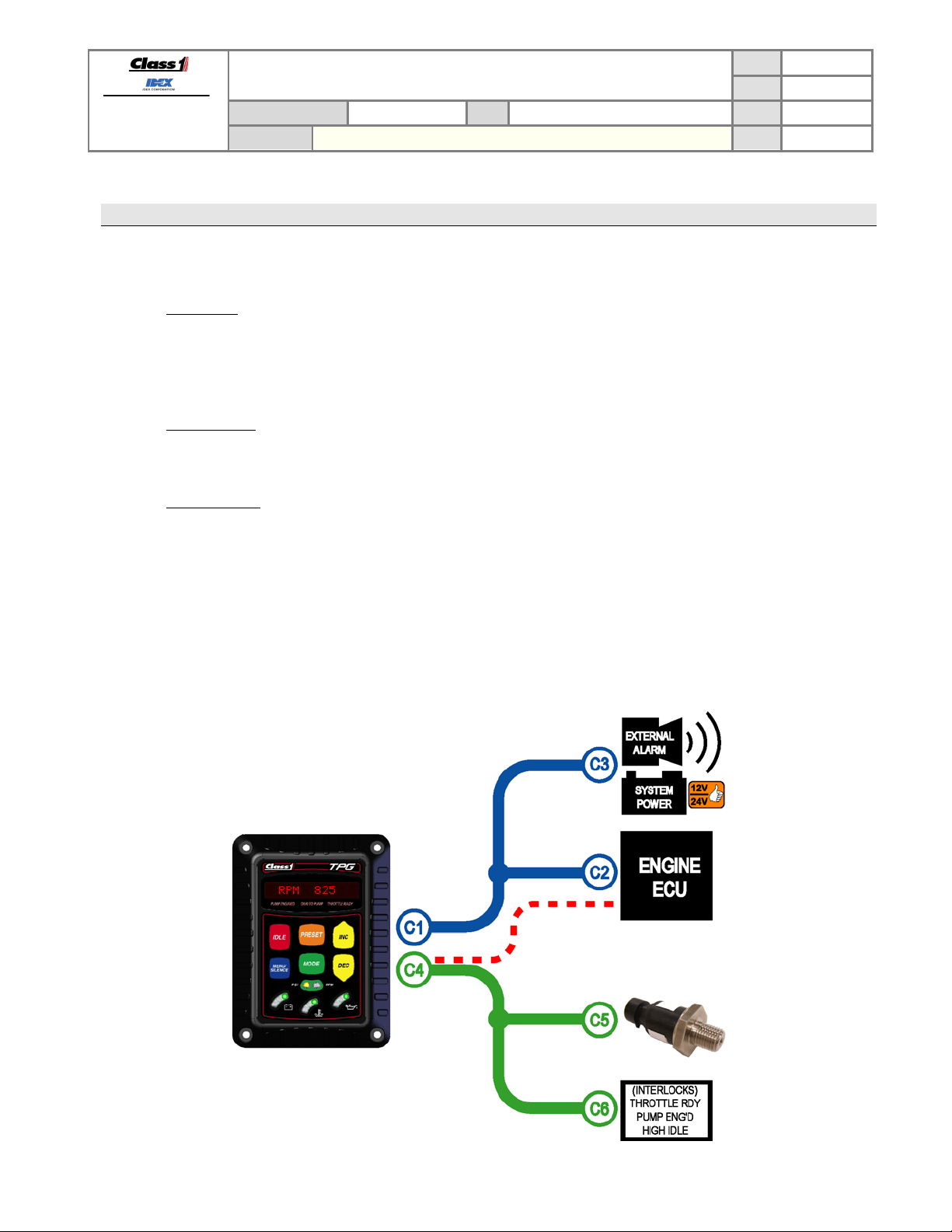
2.2. Harness detail (p/n 117666 and p/n 117683)
The main system harness (p/n 117666) is comprised of a pair of harnesses: the power/communication harness
(depicted below in blue) and the signals harness (depicted below in green).
When the analog signal control option is desired instead of the standard CAN control option then the analog control
option harness is also required (p/n 117683). This harness is actually a set of wires and pins which must be inserted
into connector C1 (depicted below with a red dashed line).
PAGE
DATE
P/N 117155 REV
BY AMS
4 OF 26
3/28/2012
1.23
Manual P/N 117684
Figure 1. Harness nomenclature.
Page 6
FORM-ENG-0018 REV A 05-27-03
607 NW 27th Ave
Ocala, FL 34475
Ph: 352-629-5020 or 1-800-533-3569
Fax : 352-629-2902 or 1-800-520-3473
PRODUCT GROUP
PRODUCT
TOTAL PRESSURE GOVERNOR (TPG)
TECHNICAL DATA SHEET
THROTTLE CONTROL
P/N 117155 REV
PAGE
DATE
BY AMS
5 OF 26
3/28/2012
1.23
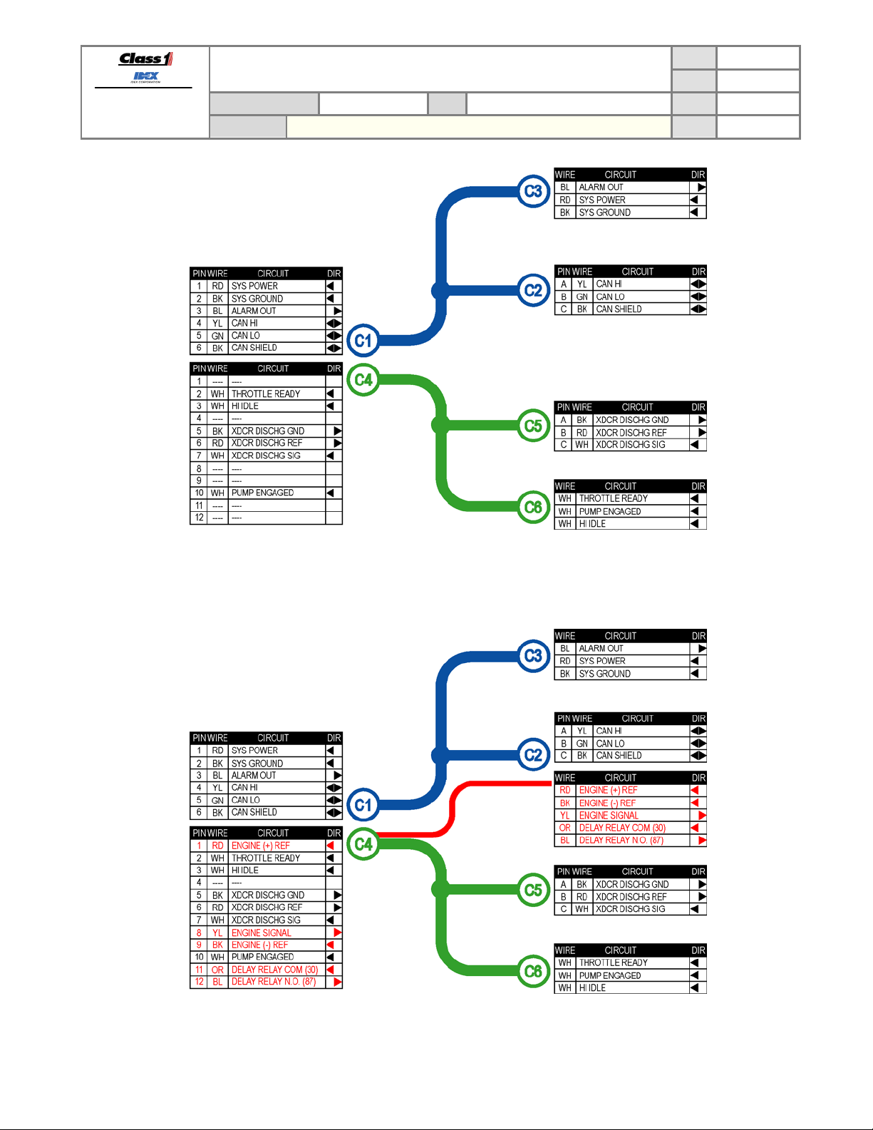
Figure 2. Harness wiring detail - p/n 117666.
Manual P/N 117684
Figure 3.
Harness wiring detail - p/n 117666 with analog option harness p/n 117683 (red).
Page 7
FORM-ENG-0018 REV A 05-27-03
607 NW 27th Ave
Ocala, FL 34475
Ph: 352-629-5020 or 1-800-533-3569
Fax : 352-629-2902 or 1-800-520-3473
PRODUCT GROUP
PRODUCT
TECHNICAL DATA SHEET
THROTTLE CONTROL
TOTAL PRESSURE GOVERNOR (TPG)
3. Total Pressure Governor Overview
The Total Pressure Governor (TPG) p/n 117155 is an SAE J1939 Controller Area Network (CAN)
device that controls engine speed using data communications directly to the engine ECU or with an
analog control signal. By operating on the J1939 network, the governor is able to monitor engine
RPM and other pertinent data directly from the engine ECU. Engi ne inf ormation is available directly
so that NFPA required instrumentation is delivered through a single unit saving panel space and
delivering engine specific warnings as determined by each engine manufacturer.
Control algorithms are optimized to take advantage of the J1939 CAN data to yield crisp and
accurate control of engine and subsequently pump speed and pressure output.
For engines that may not support the data link control, an analog output signal is available to
provide precise control of the engine speed and pressure.
PAGE
DATE
P/N 117155 REV
BY AMS
6 OF 26
3/28/2012
1.23
Manual P/N 117684
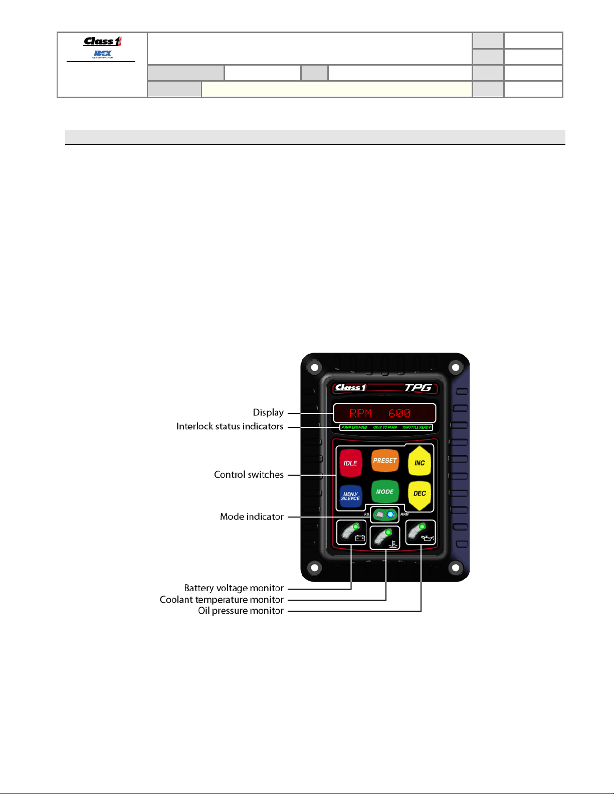
Figure 4. TPG controls and indicators.
Page 8

FORM-ENG-0018 REV A 05-27-03
607 NW 27th Ave
Ocala, FL 34475
Ph: 352-629-5020 or 1-800-533-3569
Fax : 352-629-2902 or 1-800-520-3473
3.1. Display
The display shows the pertinent governor information: engine RPM, set pressure, warning and information messages.
3.2. Interlock status indicators
Backlit text indicates the status of the three (3) interlocks: pump engaged, okay to pump, and throttle ready. Throttle
ready and pump engaged are physical inputs into the TPG’s 12 pin connector (pins 2 and 10 respectively). Okay to
pump interlock status can be configured to beco me active when both the throttle ready and pump engaged interlocks
are present (default) or when the TPG’s pin 4 physical input is active (see section 5.2.34).
3.3. Control switches
The six (6) control switches are color coded and labeled for easy identification.
3.3.1. IDLE
The IDLE switch (red) forces the governor to idle mode (standby). Pressing and holding this button for one second
while in rpm or pressure mode will cause the engine to ramp down to its idle position.
3.3.2. MENU/SILENCE
The MENU/SILENCE switch (blue) is used to silence the alarm, cycle through the display items, and enter the
setup menu.
3.3.3. PRESET
The PRESET switch (orange) sets the governor to the configured preset engine RPM while in throttle mode, or
preset pressure while in pressure mode.
3.3.4. MODE
The MODE switch (green) sets the governor to either throttle mode (RPM) or pressure mode (PSI). The correct
interlocks must be present for the system to begin governor operation: throttle ready for RPM mode, throttle ready,
pump engaged, and okay to pump for PSI mode.
3.3.5. INC
The INC [increase] switch (yellow) is used to increase the engine RPM or pressure set point.
3.3.6. DEC
The DEC [decrease] switch (yellow) is used to decrease the engine RPM or pressure set point.
3.4. Mode indicator
The mode indicator consists of two (2) LEDs to show the governor’s current operating mode. The PSI LED (yellow)
indicates the governor is operating in pressure mode and the RPM LED (blue) indicates the governor is operating in
throttle mode. When both LEDs are OFF the governor is in idle mode (standby).
PRODUCT GROUP
PRODUCT
TECHNICAL DATA SHEET
THROTTLE CONTROL
TOTAL PRESSURE GOVERNOR (TPG)
P/N 117155 REV
PAGE
DATE
BY AMS
7 OF 26
3/28/2012
1.23
Manual P/N 117684
Page 9
FORM-ENG-0018 REV A 05-27-03
607 NW 27th Ave
Ocala, FL 34475
Ph: 352-629-5020 or 1-800-533-3569
Fax : 352-629-2902 or 1-800-520-3473
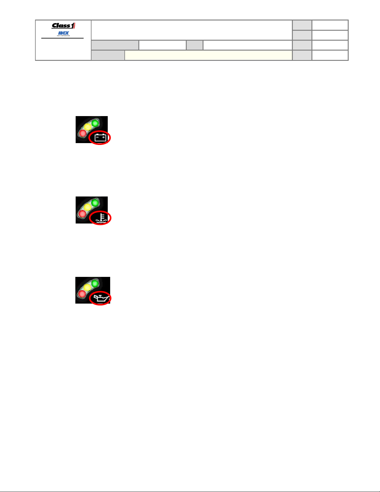
3.5. Battery voltage monitor
The battery voltage monitor is comprised of three (3) LEDs (green, yellow, and red). The active LED color indicates
the current system voltage’s range as measured by the power and ground inputs pins. The alarm will activate when
the voltage monitor is in condition RED.
3.6. Coolant temperature monitor
The coolant temperature monitor is comprised of three (3) LEDs (green, yellow, and red). The active LED color
indicates the status of the coolant temperature as reported by the J1939 network data messages (DM1). The coolant
temperature status can also be set to react to user desired points (see section 5.2.22). The alarm will activate when
the coolant temperature monitor is in condition RED.
PRODUCT GROUP
PRODUCT
TOTAL PRESSURE GOVERNOR (TPG)
• GREEN 12.5VDC and higher
• YELLOW 12.4VDC to 11.9VDC
• RED 11.8VDC and lower
TECHNICAL DATA SHEET
THROTTLE CONTROL
P/N 117155 REV
PAGE
DATE
BY AMS
8 OF 26
3/28/2012
1.23
• GREEN No active error reported by engine for coolant temperature
• YELLOW Coolant temperature high WARNING – SPN 110, FMI 16
• RED Coolant temperature high CRITICAL – SPN 110, FMI 0
3.7. Oil pressure monitor
The oil pressure monitor is comprised of three (3) LEDs (green, yellow, and red). The active LED color indicates the
status of the oil pressure as reported by the J1939 network data messages (DM1). The oil pressure status can also
be set to react to user desired points (see section 5.2.22). The alarm will activate w hen the oil monitor is in con diti on
RED.
• GREEN No active error reported by engine for oil pressure
• YELLOW Oil pressure low WARNING – SPN 100, FMI 18
• RED Oil pressure low CRITICAL – SPN 100, FMI 1
Manual P/N 117684
Page 10
FORM-ENG-0018 REV A 05-27-03
PRESET
The display shows
The display shows the
The display shows
The TPG begins normal
607 NW 27th Ave
Ocala, FL 34475
Ph: 352-629-5020 or 1-800-533-3569
Fax : 352-629-2902 or 1-800-520-3473
4. Operation
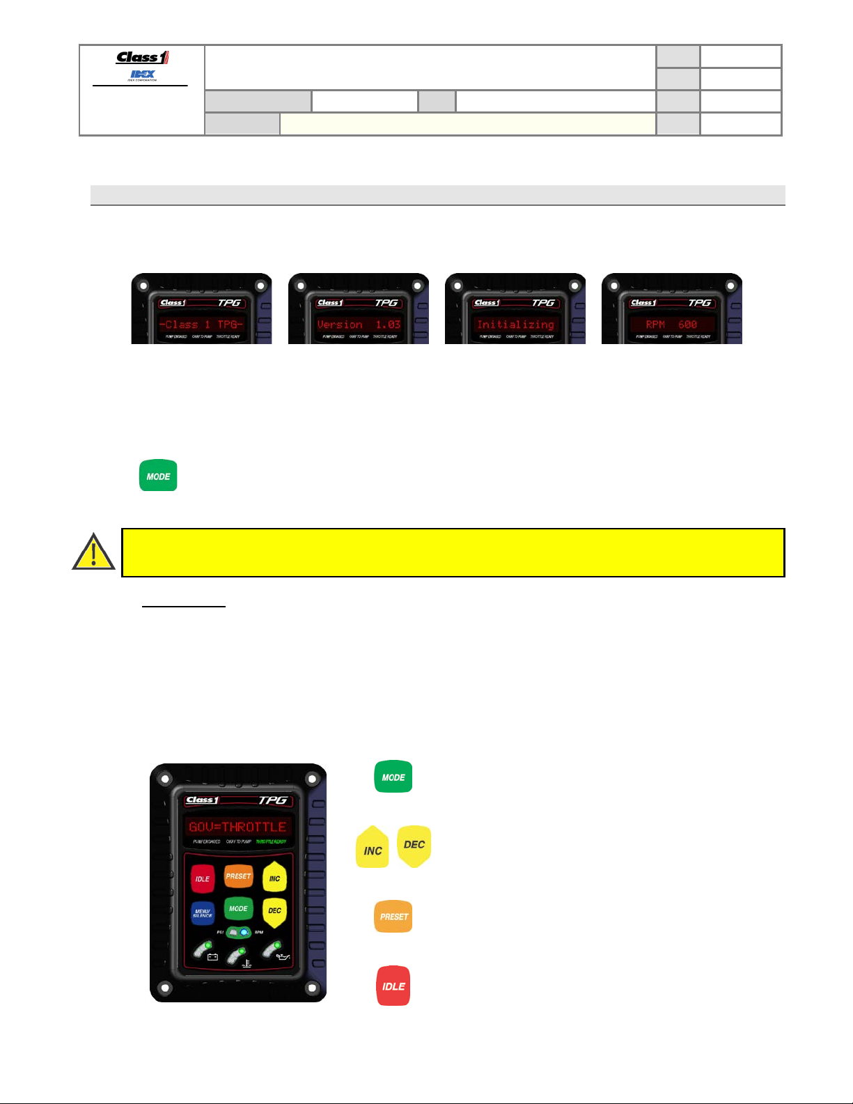
4.1. Initialization
The TPG has a five (5) second power initialization cycle and during this time the display will show:
PRODUCT GROUP
PRODUCT
TOTAL PRESSURE GOVERNOR (TPG)
TECHNICAL DATA SHEET
THROTTLE CONTROL
P/N 117155 REV
PAGE
DATE
BY AMS
9 OF 26
3/28/2012
1.23
“–Class1 TPG–“
for 1 second.
software version number
for 1 second.
“Initializing”
for 3 seconds.
operation by displaying the
engine RPM.
4.2. Operating mode selection
The TPG has two operati ng m odes : throttle mode (RPM) and pressure mode (PSI).
Press the MODE switch to select an operating mode. An operating mode will only be activated if the
required interlock(s) are in place (see section 4.3).
There is no variation in engine RPM or pump pressure when changing between throttle mode and pressure mode.
Pressure mode is the desired operating mode because it offers protection from pressure changes that could
injure personnel.
4.2.1. Throttle mode
Throttle mode (RPM) maintains a set engine RPM and will not deviate until the operator changes the RPM with
the TPG’s control switches.
Throttle mode is typically used when…
• priming the pump
• connected to a stand pipe
(Proper interlocking is required for normal operation – refer to Required Interlocking section 4.3)
• the water supply pressure stability is questionable
• acting as a relay pumper
Press the MODE switch to select throttle mode. The display will
momentarily show “GOV=THROTTLE” and the RPM mode
indicator LED will illuminate blue.
Manual P/N 117684
Press the INC switch to increase or the DEC switch to decrease
the engine RPM set point.
Press the
configured preset RPM - as long as the pump pressure is less
than 10 PSI (see section
Configure the throttle mode preset through the Setup Menu
(see section 5.2.1).
Press the IDLE switch at any time to set the TPG back to
standby. The display will momentarily show “IDLE” and both
mode indicator LEDs will be off (see section 4.5).
switch to set the engine speed to the
4.4).
Page 11

FORM-ENG-0018 REV A 05-27-03
Press the MODE switch to select pressure mode. The display
Press the PRESET switch to set the pump pressure to the
607 NW 27th Ave
Ocala, FL 34475
Ph: 352-629-5020 or 1-800-533-3569
Fax : 352-629-2902 or 1-800-520-3473
4.2.2. Pressure mode
Pressure mode (PSI) maintains a set pump pressure by monitoring the pressure transducer and modifying the
pump speed by adjusting the engine RPM. The operator can modify the set pump pressure with the TPG’s control
switches.
Pressure mode (PSI) affords the most safety to the operator by not allowing potentially hazardous pressure
spikes. The TPG will maintain the set pump pressure even when discharge lines are actively opened and closed
as long as the water supply is sufficient. The TPG will automatically increase engine speed when pump pressure
has decreased due to discharge lines being opened. The increase in engine speed will return the pump pressure
to the desired set pressure (and vice-versa when discharge lines are closed).
PAGE
TECHNICAL DATA SHEET
PRODUCT GROUP
PRODUCT
(Proper interlocking is required for normal operation – refer to Required Interlocking section 4.3)
THROTTLE CONTROL
TOTAL PRESSURE GOVERNOR (TPG)
P/N 117155 REV
will momentarily show “GOV=PRESSURE” and the PSI mode
indicator LED will illuminate yellow.
It may be necessary to press the MODE switch twice depending
on the configured first mode (see section 5.2.5).
DATE
10 OF 26
3/28/2012
1.23
BY AMS
Press the INC switch to increase or the DEC switch to decrease
the pressure set point.
configured preset. The TPG will adjust the engine RPM to
maintain the preset pressure value (see section
Configure the pressure mode preset through the Setup Menu
(see section 5.2.4).
Press the IDLE switch at any time to set the TPG back to
standby. The display will momentarily show “IDLE” and both
mode indicator LEDs will be off (see section 4.5).
4.4).
There are five control properties which can be modified to improve pressure mode performance: pressure
sensitivity, PSI time-out, PSI increase step, pressure lag, and PSI gain.
CONTROL PROPERTY DESCRIPTION DEFAULT SECTION
Controls how much difference between the set pressure and
Pressure sensitivity
actual pressure that is allowed before the TPG actively
adjusts the engine RPM to bring the pump pressure back to
6 PSI 5.2.9
the set pressure.
When the pressure drops below 30 PSI for the number of
Pressure time-out
seconds configured the engine RPM will be reduced to idle,
the alarm will sound and the OPERATOR CMD warning will
3 SEC 5.2.14
be shown in the display window (see section 4.6).
Pressure Gain
The pressure change requested with each INC or DEC switch
press.
3 PSI 5.2.14
While th e increase button is held, controls how much
Pressure lag
pressure change between the desired pressure and actual
pressure can occur before the engine RPM is adjusted to
5 PSI 5.2.29
maintain desired pressure.
Manual P/N 117684
Page 12
FORM-ENG-0018 REV A 05-27-03
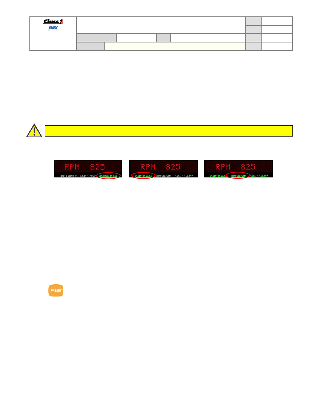
THROTTLE READY interlock
PUMP ENGAGED interlock
OKAY TO PUMP
Apply system power to pin 2 of the
Apply system power to pin 10 of the
When THROTTLE READY and
The PRESET switch brings the discharge pressure (or engine RPM, in throttle mode) to the configured
607 NW 27th Ave
Ocala, FL 34475
Ph: 352-629-5020 or 1-800-533-3569
Fax : 352-629-2902 or 1-800-520-3473
4.3. Required interlocking
The TPG requires interlocks before engi ne contr ol operations are permitted. The TPG provides two interlock inputs
that allow easy separation of pumping operations and throttle/high idle operations through two inputs dedicated as
system interlocks: THROTTLE READY (pin 2 of the 12-pin Deutsch connector) and PUMP ENGAGED (pin 10 of the
12-pin Deutsch connector).
A third interlock input (pin 4 of the 12-pin Deutsch connector) may be configured to control OKAY TO PUMP (menu
level 5, see section 5.2).
These interlock inputs are activated when system power is applied (positive polarity).
The OEM is responsible for creating safe and effecti ve interlocking routines.
The TPG utilizes back lit text below the main display to indicate interlock status.
PRODUCT GROUP
PRODUCT
TECHNICAL DATA SHEET
THROTTLE CONTROL
TOTAL PRESSURE GOVERNOR (TPG)
P/N 117155 REV
PAGE
DATE
BY AMS
11 OF 26
3/28/2012
1.23
12-pin Deutsch connector (through
OEM interlocking).
THROTTLE READY text illuminates
green.
The TPG will operate in throttle
mode (RPM) only.
4.4. PRESET switch operation
Using the PRESET switch is a method of smoothly and expeditiously attaining water pressure and flow, but it is not
intended to be the initial attack pressure. Attack pressures and flows should be determined by the actual fire status
and manually achieved for best operation.
PRESET is an operational convenience and needs to be considered as a fixed point (higher or lower than the current
point) that can be achieved with a single switch press.
Note: Initiating pumping operations is simplified by bringing the pump to a preset pressure with a single switch press.
Consequently, securing or reg aini ng contr ol operations can be aided by returning to this fixed pressure point with a
single switch press.
12-pin Deutsch connector (through
OEM interlocking).
PUMP ENGAGED text illuminates
green.
The TPG will not operate in any
mode until the THROTTLE READY
interlock is applied.
preset point (see section 5.2.2 and 5.2.4).
PUMP ENGAGED interlocks are
applied the OKAY TO PUMP text
illuminates green (default), unless
the OKAY TO PUMP interlock has
been configured to function with pin
4, then the OKAY TO PUMP text
only illuminates when pin 4 of the
12-pin Deutsch connector has
system power applied (through OEM
interlocking).
The TPG will operate in throttle
mode (RPM) or pressure mode
(PSI).
Manual P/N 117684
Page 13
FORM-ENG-0018 REV A 05-27-03
607 NW 27th Ave
Ocala, FL 34475
Ph: 352-629-5020 or 1-800-533-3569
Fax : 352-629-2902 or 1-800-520-3473
4.5. IDLE switch operation
Note: In view of the fact that driveline stress can be induced by quick changes in engine speed, depending on rpm
and torque load, the engine speed is ramped to idle over a short duration to minimize the effect of driveline kick.
4.6. Status and warning messages
The table below details the TPG’s status and warning messages.
• These codes will flash on the display while the error/warning is active.
• Multiple errors/warnings may be sequenced on the display.
• Press and hold the MENU/SILENCE switch for one second to silence the active alarm.
PRODUCT GROUP
PRODUCT
TOTAL PRESSURE GOVERNOR (TPG)
Press and hold the IDLE switch for one second to release engine RPM control back to the engine ECU. The
engine RPM will promptly go to its configured curb idle (see section 5.2.15).
ERROR CODE DESCRIPTION
SENSOR FAIL
LOW PRESSURE
OPERATOR CMD
∆ RPM LIMIT
WATER SUPPLY
∆ PSI LIMIT
NO COMM DATA
CHECK ENGINE
STOP ENGINE
OUTPUT FAIL
SELECT MODE?
SWITCH FAIL
THROT INTLK?
PAGE
TECHNICAL DATA SHEET
THROTTLE CONTROL
P/N 117155 REV
DATE
BY AMS
Signal voltage from pressure sensor is less than +0.30VDC or greater than
+4.90VDC
Pump pressure is less than 15 PSI during pressure mode operation
Pump pressure was greater than 50 PSI, but has dropped to below 30 PSI
Engine speed change of greater than 200 RPM does not yield increase in PSI
PSI decreased while RPM was increased (while in pressure mode)
PSI increased 50 PSI over set pressure point
Not receiving CAN communication data from engine ECU
Received CHECK ENGINE warning from engine ECU via CAN message
Received STOP ENGINE warning from engine ECU via CAN message
Output signal voltage differs from expected (calculated) value (no longer
displayed in version 3.2 and above)
Increase or Decrease request when no active mode (PSI/RPM) selected
Switch panel reporting an improper switch combination
Throttle ready interlock is not present when mode button is pressed
12 OF 26
3/28/2012
1.23
Manual P/N 117684
Page 14

FORM-ENG-0018 REV A 05-27-03
Display shows MENU 04 SECS and begins counting down. Continue holding IDLE and MENU
level then release).
Enter a password while at idle to direct access a menu level.
INC, INC, DEC, INC, DEC, INC, DEC, INC = menulevel 5 (restricted)
607 NW 27th Ave
Ocala, FL 34475
Ph: 352-629-5020 or 1-800-533-3569
Fax : 352-629-2902 or 1-800-520-3473
PRODUCT GROUP
PRODUCT
TOTAL PRESSURE GOVERNOR (TPG)
5. Governor Control Setup Menu
5.1. Engine compatibility
The factory default settings of the TPG make it “out of the box” ready to operate a Cummins engine programmed with
the Emergency Vehicle Calibration. Typically, for the default configuration no values will require modification, other
than changing the desired engine rpm, high-idle rpm and pump pressure preset values.
The governor is capable of controlling any engine that allows J1939 PGN0 (Torque Speed Control) messages from a
unique source address. These engines include various Detroit Diesel DDEC engines, Mercedes Benz (MBE)
engines, Volvo, and others. Programming of the source address or other parameters on the engine ECM may be
required. The Scania engine allows control by proprietary J1939 messages and is supported by the TPG. In cases
where an engine does not support data link control, the TPG can be configured to control the engine with an analog
signal coupled to the engine remote PTO throttle input.
Contact Class 1 or visit our website (www.class1.com) for a complete engine compatibility list.
5.2. Enter the setup menu
The setup menu allows access to the configuration and calibration screens. There are 5 set up menus available:
menu level 1 (basic setup men u), menu level 2, menu level 3, menu level 4 (factory menu), and menu level 5
(restricted). All configurations and calibrations are saved in non-volatile memory and will not be lost with power
disruptions.
TECHNICAL DATA SHEET
THROTTLE CONTROL
P/N 117155 REV
PAGE
DATE
BY AMS
13 OF 26
3/28/2012
1.23
Standard menu level access
The standard menu level access method allows entry into menu levels 1, 2, or 3 only. Use the Direct menu level
access method to enter menu level 4 or 5. Once a menu level has been selected, subsequent menu access will
always enter that menu level and a system re-power is required to reset the first entry menu level.
+
until the display shows *SETUP MENU* (4 seconds) and then release the switches. (If menu level
2 or menu level 3 is desired continue to hold the switches until the display shows the desired menu
Press the MENU switch to cycle through the available setup menu items.
or
Press the INC or DEC switches to modify the current menu item.
Press the PRESET switch to store the configured menu item. The display will show ---STORED---.
Press the MODE switch to exit the setup menu. The display will show --EXITMENU-- and then
resume normal operation.
Direct menu level access
INC, DEC, DEC, INC, DEC, DEC, DEC, INC = menulevel 1
+
Manual P/N 117684
or
INC, DEC, DEC, INC, DEC, DEC, INC, DEC = menulevel 2
INC, DEC, DEC, INC, DEC, DEC, INC, INC = menulevel 3
INC, DEC, DEC, INC, DEC, INC, DEC, DEC = menulevel 4 (factory)
Page 15

FORM-ENG-0018 REV A 05-27-03
607 NW 27th Ave
Ocala, FL 34475
Ph: 352-629-5020 or 1-800-533-3569
Fax : 352-629-2902 or 1-800-520-3473
Menu items in menu levels 1, 2, and 3
MENU ITEM DESCRIPTION DEFAULT MENU LEVEL
UNITS
PRESET RPM
HI-IDLE
PRESET PSI
BRIGHT
DISPLAY TEST
ROUND PSI
ALERT TONE
SENSITIVITY
-SENSOR CAL-
1ST MODE
AUTO MODE
COMM STATUS
CONTROL
RPM IDLE
RPM MAX
SOURCE ID
TSC1 RAMP
DISPLAY
PSI TIME-OUT
ALLOW PRESET
WARNINGS
WARN °F
CRIT °F
WARN PSI
CRIT PSI
PRODUCT GROUP
PRODUCT
Configures units of measure
Configures the throttle mode (RPM) preset (900 – 1400)
(Not available with message type ANLG)
Configures the high idle RPM preset (900-1400)
(Not available with message type ANLG)
Configures the pressure mode (PSI) preset (90 – 130)
Configures the display’s brightness level (1-15)
Tests all of the pixels of the main display
Configures the rounding of the pressure value
Alert tones are indicated by a double chirp of the alarm output and
do not indicate alarm conditions. Enable/disable the alert tones.
Configures the pressure sensitivity window (4 – 12)
Calibrates the zero point of the pressure sensor
Configures the first mode active when the MODE switch is pressed
(interlocks permitting)
Configures if governor automatically enters into psi mode upon
pump engagement.
(Only available when 1st mode menu item is set to PSI and menu level was 3 or greater)
Allows viewing of CAN messages per second and received errors
Configure control mode and message for engine
Configure / adjust the idle rpm
(Not available with message type ANLG)
Configure / adjust the maximum rpm commanded by governor
(Not available with message type ANLG or CFPG)
Configure the CAN source ID for the TPG
(only available with message type PGN0 or SCA N)
Configure the RPM ramp speed of TSC1/PGN0 control mode
(only available with message type PGN0)
Configure primary display while in pressure mode (rpm or pressure)
Configures the amount of seconds the TPG will wait after pressure
has dropped below 30 PSI before dropping to IDLE mode
Configure enable/disable rpm preset if pump is under pressure
Configures source of the panel warning LED’s (data bus or user
defined)
Configure the yellow (warning) engine temp setpoint
(only available when WARNINGS is set to Usr)
Configure the red (critical) engine temp setpoint
(only available when WARNINGS is set to Usr)
Configure the yellow (warning) oil pressure setpoint
(only available when WARNINGS is set to Usr)
Configure the red (critical) oil pressure setpoint
(only available when WARNINGS is set to Usr)
TECHNICAL DATA SHEET
THROTTLE CONTROL
TOTAL PRESSURE GOVERNOR (TPG)
P/N 117155 REV
PAGE
DATE
BY AMS
PSI / ºF
1000
1100
90
15
N/A
N
Y
+/- 6 PSI
142 COUNTS
PSI
NO
N/A
CFPG (Cummins)
700
2200
7
0
RPM
5
NO
Bus
-
-
-
-
14 OF 26
3/28/2012
1.23
1
1*
1*
1
1
1
1
2
2
2
2
3*
2
3
3*
3*
3*
3*
3
3
3
3
3*
3*
3*
3*
Manual P/N 117684
Page 16

FORM-ENG-0018 REV A 05-27-03
607 NW 27th Ave
Ocala, FL 34475
Ph: 352-629-5020 or 1-800-533-3569
Fax : 352-629-2902 or 1-800-520-3473
MENU ITEM DESCRIPTION DEFAULT MENU LEVEL
XDCR
FACTORY DFLT
* Option dependent on other menu selections made
Menu items in menu level 4
MENU ITEM DESCRIPTION DEFAULT MENU LEVEL
POC ASSERT
GOV GAIN
PRESS GAIN
DITHER
LAG (∆PSI)
PUMP HOURS
BCM1 VER
SCANIA MODE
IDLE STEPS
* Option dependent on other menu selections made
PRODUCT GROUP
PRODUCT
TOTAL PRESSURE GOVERNOR (TPG)
Configures transducer type (300 or 600 psi) (300 default)
Returns all menu parameters to the factory default state
(Cummins Control – message type CFPG)
Configures when idle offset is asserted (with power on cycle or mode
switch)
(Only available with message type ANLG)
Configures the RPM change requested per INC or DEC switch press
(Only available with message type ANLG)
Configures the pressure change requested per INC or DEC switch
press
Configure the engine handshake
(Only available with message type PGN0)
Controls the response of the pressure increase when the INC button
is held while in pressure mode.
Set/reset the number of pump hours
Configures the Scania BCM version
(Only available with message type SCAN)
Configures the Scania engine control type: NORMAL or STIFF
(Only available with message type SCAN)
Configures the idle offset voltage for analog control mode
(Only available with message type ANLG)
TECHNICAL DATA SHEET
THROTTLE CONTROL
P/N 117155 REV
PAGE
DATE
BY AMS
300
N/A
NO
15
3 PSI
NO
5 PSI
N/A
1
NORMAL
32
15 OF 26
3/28/2012
1.23
3
3
4*
4*
4
4*
4*
4
4*
4*
4*
Menu items in menu level 5
MENU ITEM DESCRIPTION DEFAULT MENU LEVEL
OK2PUMP
SPN 3350
SPN 696
HIDLE MODE
BUS INTLKS
VOLTS
SMOOTHING
ENGINE ID
* Option dependent on other menu selections made
Manual P/N 117684
Configure the “okay to pump” interlock source
Configure the PGN0 control purpose
(only available with message type PGN0)
Configure the Engine Requested Speed Control Condition
(only available with message type PGN0)
Configure the high idle mode
Configure the bus interlocks
Calibrate the battery voltage display (+0.0 to +0.5 volts)
Configure pressure averaging (smoothing – NO, LO, HI)
Configure the CAN source ID where the TPG receives its engine
information from. Normally this will always be address 0 unless
some kind of interface module is used between the engine and TPG
NORM
P32
3
1
N
+0.0 volts
LO
0
5
5*
5*
5
5
5
5
5
Page 17

FORM-ENG-0018 REV A 05-27-03
607 NW 27th Ave
Ocala, FL 34475
Ph: 352-629-5020 or 1-800-533-3569
Fax : 352-629-2902 or 1-800-520-3473
PRODUCT GROUP
PRODUCT
5.2.1. UNITS (unit of measure configuration)
This menu item allows configuration of the display units of measure.
Use the INC and DEC keys to select the desired units of measure. The options include
Range = PSI / ºF, kPa / ºC, bar / ºC [default = PSI / ºF]
5.2.2. PRESET RPM (throttle preset configuration)
This menu item allows configuration of the throttle mode preset.
The display will show PSETrpm XXXX. Use the INC and DEC switches to adjust the RPM value desired for the
throttle mode preset.
Range = 900 RPM to 1400 RPM (in 25 RPM steps). [default = 1000 RPM]
5.2.3. HI-IDLE (high idle configuration)
This menu item allows configuration of the high idle (fast idle) setpoint.
The display will show Hi-Idle= XXX. Use the INC and DEC switches to adjust the RPM value desired for the high
idle setpoint.
TECHNICAL DATA SHEET
THROTTLE CONTROL
TOTAL PRESSURE GOVERNOR (TPG)
PAGE
DATE
P/N 117155 REV
BY AMS
PSI/°F, kPa/°C, bar/°C.
16 OF 26
3/28/2012
1.23
Range = 900 RPM to 1400 RPM (in 25 RPM steps). [default = 1100 RPM]
5.2.4. PRESET PSI (pressure preset configuration)
This menu item allows configuration of the pressure mode preset.
The display will show PSETpsi XXX. Use the INC and DEC switches to adjust the PSI value desired for the
pressure mode preset.
Range = 90 PSI to 130 PSI (in 10 PSI steps) [default = 100 PSI]
5.2.5. BRIGHT (display brightness)
This menu item allows configuration the display’s brightness level.
The display will show BRIGHTNESS=X. Use the INC and DEC switches to adjust the value desired display
brightness.
Range = 1 to 15 (1 is dimmest sett i ng) [default = 15]
5.2.6. DISPLAY TEST
This menu item allows testing of all of the pixels of the main display and all of the LEDs.
The display will show DISPLAY TEST. Use the INC or DEC switch to turn on all of the LEDs and pixels in the
display.
5.2.7. ROUND PSI (configure rounding of the pressure value)
This menu item allows enabling/disabling of the “round to nearest 5” of the pressure value.
The display will show ROUND PSI: X. Use the INC and DEC switches to sel e ct Y (yes) or N (no).
Round PSI = Y (round to nearest 5) or N (don’t round). [default = N]
5.2.8. ALERT TONE (configure alert tones)
This menu item allows enabling/disabling of the alert tones. The alert tones are sounded through the external
alarm output (pin 3 of the 6-pin connector).
The display will show ALERT TONE:X. Use the INC and DEC switches to select Y (yes, enabled) or N (no,
disabled).
Range = Y (Alert tones ON) or N (Alert tones OFF). [default = Y]
Manual P/N 117684
Page 18

FORM-ENG-0018 REV A 05-27-03
607 NW 27th Ave
Ocala, FL 34475
Ph: 352-629-5020 or 1-800-533-3569
Fax : 352-629-2902 or 1-800-520-3473
PRODUCT GROUP
PRODUCT
5.2.9. SENSITIVITY (pressure sensitivity configuration)
This menu item allows configuration of the pressure mode sensitivity window. This window dictates how much
pressure difference must occur before the TPG adjusts the engine RPM to maintain the desired set pressure.
The display will show GOV± XX PSI. Use the INC and DEC switches to adjust the PSI value desired for the
pressure mode sensitivity.
Range = 4 PSI to 12 PSI (in 1 PSI steps). [default = 6 PSI]
5.2.10. SENSOR CAL (pressure sensor calibration)
This menu item allows calibration of the pressure sensor.
The display will show –SENSOR CAL-. See section 7.3 for the calibration procedure.
5.2.11. 1st MODE (first active mode configuration)
This menu item allows configuration of the governor mode active when the MODE switch is first presse d.
The display will show 1
Proper interlocks must be established for the configured 1st mode to become active during operation.
TECHNICAL DATA SHEET
THROTTLE CONTROL
TOTAL PRESSURE GOVERNOR (TPG)
st
MODE=XXX. Use the INC and DEC switches to select the desired mode (PSI or RPM).
PAGE
DATE
P/N 117155 REV
BY AMS
17 OF 26
3/28/2012
1.23
Range = RPM (throttle mode) or PSI (pressure mode). [default = PSI]
5.2.12. AUTO MODE (pressure mode automatically entered on pump engagement)
This menu item allows configuration of automatically entering pressure mode when pump engagement occurs
(AUTO MODE?:Y). Note that this option will only be available if the 1
st
mode parameter (section 5.2.11) is set to
pressure mode (PSI). When this parameter is enabled, the governor will be put in pressure mode when the pump
is changed from a disengaged to an engaged position (interlocks permitting). Thereafter, when a user selects the
IDLE (standby) mode, the governor will remain in standby mode until a new mode is selected.
Range = Y1 (Automode ON, Throttle Ready first then Pump Engaged),
Y2 (Automode ON, Pump Engaged first then Throttle Ready),
N (Automode OFF). [default = N]
5.2.13. COMM STATUS (view the CAN communication status)
This menu item allows viewing of the number of CAN messages per second and received errors. This menu item is
only available when the CAN message type is set to CFPG.
The display will show COMM STATUS. Use the INC and DEC switches to toggle between message per second
and received errors.
5.2.14. CONTROL (engine control message type)
This menu item allows configuration of the CAN or ANALOG control message type.
CFPG – Cummins Fire Pressure Governor, uses Cummins proprietary control message to control engine speed.
PGN0 – Uses J1939, PGN0 – Torque Speed Control message to control engine speed.
SCAN – SCANia, uses the Scania bodywork control message 1.
ANLG – Uses analog voltage signal to control remote th rottle input on engine.
PWM – Uses pulse width modulation control signal (12-85%, 400 Hz).
VLVO – Uses Volvo specific PTO control commands for Volvo FE/FL series engines running through
a Volvo bodybuilder control module. This method should not be used when the TPG is directly
connected to the engine CAN bus. Volvo FM/FH series engines should use the standard PGN0
control mode and set the Engine ID variable to the address of the body builder module.
The display will show CONTROL=XXXX. Use the INC and DEC switches to adjust the control message type.
Range = CFPG, PGN0, SCAN, ANLG., PWM, VLVO [default = CFPG]
Manual P/N 117684
Page 19

FORM-ENG-0018 REV A 05-27-03
607 NW 27th Ave
Ocala, FL 34475
Ph: 352-629-5020 or 1-800-533-3569
Fax : 352-629-2902 or 1-800-520-3473
5.2.15. RPMidle (idle RPM value)
This menu item allows configuration of the idle RPM.
The display will show RPMIdle=XXXX. Use the INC and DEC switches to adjust the RPM value desired for idle.
Note: cannot be adjusted below the engine’s curb idle sp eed .
Range = 650 RPM to 900 RPM (in 25 RPM steps). [default = 700 RPM]
5.2.16. RPMmaxi (maximum RPM value)
This menu item allows configuration of the maximum RPM that will be commanded when in PGN0 or SCANia
mode. The display will show RPMmaxi=XXXX. Use the INC and DEC switches to adjust the maximum RPM value
desired. This value cannot be adjusted above maximum governed speed.
Range = 1900 RPM to 2500 RPM (in 25 RPM steps). [default = 2200 RPM]
PRODUCT GROUP
PRODUCT
TOTAL PRESSURE GOVERNOR (TPG)
Note: When control type is configured for Volvo (VLVO) or MAN the minimum value can be set down to
1500 RPM.
TECHNICAL DATA SHEET
THROTTLE CONTROL
P/N 117155 REV
PAGE
DATE
BY AMS
18 OF 26
3/28/2012
1.23
5.2.17. SourceID (CAN message source identification)
This menu item allows configuration of the CAN source message ID number.
The display will show
SourceID=X. Use the INC and DEC switches to adjust the CAN source message ID.
Range = 0 – 255. [default = 7]
5.2.18. TSC1 RAMP (TSC1/PGN0 control mode RPM ramp speed)
This menu item allows configuration of the engine RPM ramp speed in TSC 1/P GN 0 control mode .
The display will show
TSC1 RAMP: X. Use the INC and DEC switches to adjust the ramp speed.
Range = 0 – 40. [default = 0]
5.2.19. DISPLAY (primary display in pressure mode) This menu item allow configuration of the display data while operating in pressure mode. The display can show
either engine speed (DISPLAY: RPM), or pump pressure (DISPLAY: PSI). The pump pressure will be displayed in
the correct units of measure (psi, kPa, or bar) selected by the user.
Note: The pressure display cannot be used as the master pressure gauge per NFPA 1901.
Range = RPM or PSI. [default = RPM]
5.2.20. PSI TIME-OUT (pressure time out)
This menu item allows configuration of the low pressure time out. When the TPG is governing in pressure mode
and the pressure falls below 30 PSI the TPG will wait the configured number of seconds to allow the pressure to
rise before dropping to IDLE.
The display will show PSI TIME-OUT. Use the INC and DEC switches to adjust the value desired for the pressure
time out.
Range = 3 seconds to 10 seconds (in 1 second steps). [default = 5 seconds]
5.2.21. ALLOW PRESET (allow RPM preset use when pressure is detected)
This menu item allows enabling/disabling of throttle mode preset usage when pump pressure over 10 PSI is
detected.
The display will show PRESET RPM=X. Use the INC and DEC switches to select Y (yes, enabled) or N (no,
disabled).
Range = Y (enabled) or N (disabled). [default = N]
Manual P/N 117684
Page 20

FORM-ENG-0018 REV A 05-27-03
607 NW 27th Ave
Ocala, FL 34475
Ph: 352-629-5020 or 1-800-533-3569
Fax : 352-629-2902 or 1-800-520-3473
PRODUCT GROUP
PRODUCT
5.2.22. WARNINGS (data monitor warning configuration)
This menu item allows configuration of the source for engine warnings. Warnings can be determined by engine
diagnostic messages (DM1 messages) over the data bus (Bus), or at setpoints defined by the user based on J1939
oil pressure and engine temperature data (Usr).
The preferred and most accurate method is to use Bus warnings from the engine diagnostic system. Note that not
all engines support this feature, contact Class1 customer support for more information.
Range = Bus (bus controlled) or Usr (user configured). [default = Bus]
When the Usr configuration is selected the following setpoints will be assigned next.
A. WARN ºF (USER DEFINED ENGINE TEMPERATURE HIGH WARNING - YELLOW LED)
B. CRIT ºF (USER DEFINED ENGINE TEMPERATURE HIGH CRITICAL - RED LED)
C. WARN PSI (USER DEFINED OIL PRESSURE LOW WARNING - YELLOW LED)
D. CRIT PSI (USER DEFINED OIL PRESSURE LOW CRITICAL - RED LED)
5.2.23. XDUCR (discharge pressure transducer range)
This menu item allows configuration the discharge pressure transducer’s range (0 to 300 PSI, or 0 to 600 PSI).
The display will show XDCR= XXXPSI. Use the INC and DEC switches to adjust the value desired for the pressure
change per button press.
TECHNICAL DATA SHEET
THROTTLE CONTROL
TOTAL PRESSURE GOVERNOR (TPG)
PAGE
DATE
P/N 117155 REV
BY AMS
19 OF 26
3/28/2012
1.23
Range = 300 PSI or 600 PSI. [default = 300 PSI]
5.2.24. FACTORY DFLT (Set factory defaults)
This menu item allows setting the TPG back to the factory defaults.
The display will show FACTORY DFLT. Press the PRESET switch to load the defaults.
Refer to the menu level tables for the default values (section 5.2).
5.2.25. POC ASSERT (Power On Cycle assertion)
This menu item allows enabling/disabling of the analog control signal idle voltage assertion at power-up. When the
POC ASSERT is enabled the analog control signal will be set to the configured idle voltage at the start of the TPG’s
power cycle. If the POC ASSERT is disabled the analog control signal will be set to the minimum configured level
at the start of the TPG’s power cycle.
The display will show POC ASSERT:X. Use the INC and DEC switches to select Y or N.
Range = Y (enabled) or N (disabled). [default = N]
5.2.26. GOV GAIN (RPM change per step)
This menu item allows configuration of the RPM change per step. A larger number changes the RPM more with
each INC or DEC switch press.
The display will show GOV GAIN :XX. Use the INC and DEC switches to adjust the value.
Range = 0 to 35 [default = 15]
5.2.27. PRESS GAIN (PSI change per step)
This menu item allows configuration of the psi change per step. A larger number changes the PSI more with eac h
INC or DEC switch press.
The display will show X PSI/STEP. Use the INC and DEC switches to adjust the value.
Range = 1 to 5 [default = 3 PSI/STEP]
Manual P/N 117684
Page 21

FORM-ENG-0018 REV A 05-27-03
607 NW 27th Ave
Ocala, FL 34475
Ph: 352-629-5020 or 1-800-533-3569
Fax : 352-629-2902 or 1-800-520-3473
5.2.28. DITHER (Engine handshake)
This menu item allows enabling/disabling of engine handshake. When enabled, the TPG will vary the engine speed
+/- 5 RPM around the desired engine speed. Some engines may require consistent RPM modification in order to
maintain remote RPM control.
The display will show DITHER=X. Use the INC and DEC switches to select Y or N.
Range = Y (enabled) or N (disabled). [default = N]
5.2.29. LAG ∆PSI (Pressure lag)
This menu item allows configuration of the pressur e lag which defines the maximum allowable difference that the
actual pressure is behind the commanded set-point before a “wait” (catch up) state is introduced while operating in
pressure mode.
The display will show LAG (∆PSI)=X. Use the INC and DEC switches to adjust the pressure lag value.
Range = 1 PSI to 20 PSI (in 1 PSI steps). [default = 5 PSI]
5.2.30. PUMP HOURS
This menu item allows setting/resetting of the total pump hours.
The display will show PUMP X.Xh. Use the INC and DEC switches to adjust the pump hours.
PRODUCT GROUP
PRODUCT
TECHNICAL DATA SHEET
THROTTLE CONTROL
TOTAL PRESSURE GOVERNOR (TPG)
P/N 117155 REV
PAGE
DATE
BY AMS
20 OF 26
3/28/2012
1.23
Range = 0.0 to 999.9 hours (in 0.1 hour steps). [default = 0]
5.2.31. BCM1 VER (Body Control Message 1 version)
This menu item allows configuration of the message configuration version transmitted in the Scania
Body Control Message 1.
The display will show BCM1 VER: X. Use the INC and DEC switches to adjust the value.
Range = 0 to 255. [default = 1]
5.2.32. SCANIA MODE? (Scania governor type)
This menu item allows configuration of the Scania requested governor type in the Body Control Message 1.
The display will show MODE: XXXXXX. Use the INC and DEC switches to adjust the value.
Range = NORMAL or STIFF. [default = NORMAL]
5.2.33. IDLE STEPS (Analog control idle)
This menu item allows the configuration of the analog control signal idle voltage.
The display will show IdleSteps:XX. Use the INC and DEC switches to adjust the value.
Range = 0 to 60 [default = 32]
5.2.34. OKAY2PUMP (Okay to pump interlock source)
This menu item allows the configuration of the “okay to pump” interlock source.
NORM – The OKAY TO PUMP text only illuminates when the throttle ready and pump engaged interlocks are
active.
PIN4 – The OKAY TO PUMP text only illuminates when pin 4 of the 12-pin Deutsch connector has power
applied.
The display will show OK2PUMP=X. Use the INC and DEC switches to adjust the value.
Range = NORM or PIN4 [default = NORM]
Manual P/N 117684
Page 22

FORM-ENG-0018 REV A 05-27-03
607 NW 27th Ave
Ocala, FL 34475
Ph: 352-629-5020 or 1-800-533-3569
Fax : 352-629-2902 or 1-800-520-3473
PRODUCT GROUP
PRODUCT
5.2.35. SPN 3350 (TSC1 – SPN 3350)
This menu item allows configuration of the Torque Speed Control 1 (TSC1) control purpose message.
P03 – PTO governor control p ur pos e.
P32 – Temporary power-trai n control purpose.
The display will show SPN 3350:XXX
Range = P03 or P32. [default = P32]
5.2.36. SPN 696 (Engine Requested Speed Control Condition)
This menu item allows configuration of the CAN Engine Requested Speed Control Condition (SPN 696), as defined
in SAE J1939 for the TSC1/PGN0 speed control command. Possible values are:
0 – Transient optimized for driv eline dis eng aged and non-lo c kup con diti on s.
1 – Stability optimized for driv e line di seng age d and non-lockup conditions.
2 – Stability optimized for driveline engaged and/or and in lockup condition 1 (e.g. vehicle driveline).
3 – Stability optimized for driveline engaged and/or and in lockup condition 2 (e.g. PTO driveline).
The display will show SPN 696:X. Use the INC and DEC switches to adjust the Engine Requested Speed Control
Condition.
TECHNICAL DATA SHEET
THROTTLE CONTROL
TOTAL PRESSURE GOVERNOR (TPG)
. Use the INC and DEC switches to adjust the CAN purpose.
P/N 117155 REV
PAGE
DATE
BY AMS
21 OF 26
3/28/2012
1.23
Range = 0 to 3. [default = 3]
5.2.37. HI IDLE MODE
This menu item allows configuration of the high idle mode.
1 – Normal.
2 – Only allow high idle if engine speed > 600 RPM, transmission is in neutral, and okay to pump interlock is OFF.
Forces t he throttle ready interlock OFF when transmission is NOT in neutral or 4th gear.
The display will show HIDLE MODE:X
. Use the INC and DEC switches to adjust the value.
Range = 1 or 2. [default = 1]
5.2.38. BUS INTLKS (Bus message control of throttle ready interlock)
This menu item allows configuration of the bus interlocks.
N – Normal, throttle ready interlock ON with its physical input pin.
Y – Forces throttle ready interlock ON when transmission is in Neutral.
The display will show BUS INTLKS:X
. Use the INC and DEC switches to adjust the value.
Range = Y or N. [default = N]
5.2.39. VOLTS (Voltage display calibration)
This menu item allows calibration of the voltage display.
The display will show VOLTS XX.X V. Use the INC and DEC switches to adjust the voltage level.
Range = voltage + 0.0 to voltage + 0.5 [default = 0]
5.2.40. SMOOTHING (Pressure display averaging)
This menu item allows configuration of the smoothing (averaging) method of the pres sure d ispl ay .
NO – No averaging of pressure.
LO – Average of 4 pressure samples while within pressure stasis window.
HI – Average of 8 pressure samples while within pressure stasis window.
The display will show SMOOTHING:XX. Use the INC and DEC switches to adjust the value.
Range = NO, LO, or HI [default = NO]
Manual P/N 117684
Page 23

FORM-ENG-0018 REV A 05-27-03
607 NW 27th Ave
Ocala, FL 34475
Ph: 352-629-5020 or 1-800-533-3569
Fax : 352-629-2902 or 1-800-520-3473
PRODUCT GROUP
PRODUCT
5.2.41. ENGINE ID (Source ID of received engine messages)
This menu item allows configuration of the CAN source ID for engine messages received by the TPG.
The display will show
EngineID=X. Use the INC and DEC switches to adjust the CAN engine source ID.
If the TPG continuously displays the NO COMM DATA message with the engine running and the CAN bus
connected verify the setting of this parameter. Where the TPG is directly connected to the engine’s CAN bus the
address should usually be 0 but if there is a gateway module between the engine and TPG then this parameter
needs to be set to the address from which the gateway module transmits.
Range = 0 – 255. [default = 0]
TECHNICAL DATA SHEET
THROTTLE CONTROL
TOTAL PRESSURE GOVERNOR (TPG)
PAGE
DATE
P/N 117155 REV
BY AMS
22 OF 26
3/28/2012
1.23
Manual P/N 117684
Page 24

FORM-ENG-0018 REV A 05-27-03
607 NW 27th Ave
Ocala, FL 34475
Ph: 352-629-5020 or 1-800-533-3569
Fax : 352-629-2902 or 1-800-520-3473
PRODUCT GROUP
PRODUCT
TOTAL PRESSURE GOVERNOR (TPG)
TECHNICAL DATA SHEET
THROTTLE CONTROL
P/N 117155 REV
PAGE
DATE
BY AMS
23 OF 26
3/28/2012
1.23
6. Special Function Passwords (See section 5.2 for procedure on entering passwords)
6.1. Setting control message transmission requirements
DEC, INC, INC, INC, DEC, DEC, DEC, DEC
Engine control message is not transmitted when at idle (no mode selected) - displays message "NOTX AT IDLE" after
password is entered. This can be useful if there is more than one device on a vehicle which is controlling the RPM externally
over the CAN bus.
DEC, INC, INC, INC, DEC, DEC, DEC, INC
Engine control message is transmitted whenever the throttle interlock is active - displays message "TX AT IDLE" after
password is entered. This was the standard operation for TPG version 3.2 and below and is the default on newer versions.
6.2. Setting control for specific engine types
DEC, INC, DEC, INC, DEC, DEC, DEC, DEC
NORMAL_Engine = standard TSC1, no transmit at IDLE or without throttle ready interlock.
DEC, INC, DEC, INC, DEC, DEC, DEC, INC
NORMAL_Engine_2 = standard TSC1, but transmits at idl e without throttle ready interlock.
DEC, INC, DEC, INC, DEC, DEC, INC, DEC
FAW_Engine = special TSC1, transmits at idle without throttle ready interlock, always "speed control".
DEC, INC, DEC, INC, DEC, DEC, INC, INC
FAW_Engine_2 = special TSC1, transmits at idle without throttle ready interlock, standard "override disabled" and
"speed control".
DEC, INC, DEC, INC, DEC, INC, DEC, DEC
MAN_Engine = special TSC1, no transmit at IDLE or without throttle ready interlock.
DEC, INC, DEC, INC, DEC, INC, DEC, INC
MAN_Engine_2 = special TSC1, but transmits at idle without throttle ready interlock.
6.3. Configuring transmission of Hydraulic Pressure Governor message
DEC, INC, INC, DEC, DEC, DEC, DEC, DEC
Transmit HPG message (default) - displays message "HPG = ON" after password is entered.
DEC, INC, INC, DEC, DEC, DEC, DEC, INC
Don't transmit HPG message - displays message "HPG = OFF" after password is entered.
DEC, INC, INC, DEC, INC, DEC, DEC, DEC
HPG message transmits mode normally - displays message "HPG MODE = NOR" after password is entered.
DEC, INC, INC, DEC, INC, DEC, DEC, INC
HPG message transmits PSI mode always - displays message "HPG MODE = PSI" after password is entered.
Manual P/N 117684
Page 25

FORM-ENG-0018 REV A 05-27-03
INC, DEC, DEC, INC, DEC, DEC, INC, INC
607 NW 27th Ave
Ocala, FL 34475
Ph: 352-629-5020 or 1-800-533-3569
Fax : 352-629-2902 or 1-800-520-3473
PRODUCT GROUP
PRODUCT
TOTAL PRESSURE GOVERNOR (TPG)
7. Configuration
7.1. Configure the unit of measure
The TPG can be configured for English (PSI, ºF) of Metric (kPa or bar, ºC) units of measure.
TECHNICAL DATA SHEET
THROTTLE CONTROL
P/N 117155 REV
PAGE
DATE
BY AMS
24 OF 26
3/28/2012
1.23
Follow the sequence below to set the TPG’s unit of measure.
+
ONCE
ONCE
ONCE
ONCE
Display shows MENU 04 SECS and begins counting down. Continue holding IDLE and
MENU until the display shows *SETUP MENU* (4 seconds).
The display shows the menu item: UNITS: XXX/ºX.
Press the INC switch to select the desired unit of measure: PSI/ºF, kPa/ºC, or bar/ ºC.
Press the PRESET switch once. The display shows ---STORED---. The unit of
measure has been saved.
Press the IDLE switch once. The display shows —EXITMENU— and then restarts
normal operation.
7.2. Select pressure transducer range (300 PSI, 600 PSI)
Normally the default 300 PSI transducer is sufficient for most pump applications but if a higher pump pressure range
is required the TPG can be programmed to use a 600 PSI transducer.
Follow the sequence below to select the desired pressure transducer range.
Enter menu level 3 by pressing and holding the IDLE switch while entering
+
or
the following password.
ONCE
ONCE
Manual P/N 117684
Toggle the MENU/SILENCE switch until the display shows XDCR= XXX.
(XXX = 300 or 600)
Press the INC switch to select the desired pressure transducer range (300 or 600).
Press the PRESET switch once. The display shows --- STORED---. The pressure
transducer range has been saved.
Press the IDLE switch once. The display shows —EXITMENU— and then restarts
normal operation.
Page 26
FORM-ENG-0018 REV A 05-27-03
MENU 04 SECS
(2 seconds).
Press the INC switch and hold. The display shows DIS:LIVE=XXX. Verify the value is
DIS:ZERO=XXX.
Enter menu level 3 by pressing and holding the IDLE switch while entering
INC, DEC, DEC, INC, DEC, DEC, INC, INC
Press the IDLE switch once. The display shows —EXITMENU— and then restarts
607 NW 27th Ave
Ocala, FL 34475
Ph: 352-629-5020 or 1-800-533-3569
Fax : 352-629-2902 or 1-800-520-3473
PRODUCT GROUP
PRODUCT
7.3. Zero calibrate the pressure transducer
The pressure indicated by the TPG may not show ‘0’ when the pump discharge pressure is actually zero due to
ambient pressure and altitude at your locale.
TECHNICAL DATA SHEET
THROTTLE CONTROL
TOTAL PRESSURE GOVERNOR (TPG)
PAGE
DATE
P/N 117155 REV
BY AMS
25 OF 26
3/28/2012
1.23
Follow the sequence below to zero calibrate the pressure transducer.
+
3 times
ONCE
+ HOLD
ONCE
ONCE
Display shows
MENU until the display shows *SETUP MENU* (4 seconds) and then MENU LEVEL 2
The display shows the menu item: -SENSOR CAL-.
Press the INC switch once. The display shows INT:ZERO=XXX.
between 130 and 155. Release the INC switch. The display will show
Press the PRESET switch once. The display shows NEW ZERO=XXX. Verify the
value is between 130 and 155.
Press the IDLE switch once. The display shows —EXITMENU— and then restarts
normal operation.
and begins counting down. Continue holding IDLE and
7.4. Configure the engine control method
The TPG has 4 engine control methods to cover several engine types and configuration.
CFPG – Cummins Fire Pressure Governor, uses Cummins proprietary control message to control engine speed.
PGN0 – Uses J1939, PGN0 – Torque Speed Control message to control engine speed.
SCAN – SCANia, uses the Scania bodywork control message 1.
ANLG – Uses analog voltage signal to control remote throttle input on engine.
PWM – Uses pulse width modulation control signal (12-85%, 400 Hz).
VLVO – Uses Volvo specific PTO control commands for Volvo FE/FL series engines running through a bodybuilder
module.
+
ONCE
OR
ONCE
ONCE
Manual P/N 117684
or
The display shows the menu item: CONTROL=XXXX (CFPG, PGN0, SCAN, ANLG,
PWM)
Select the desired engine control method: CFPG, PGN0, SCAN, or ANLG
Press the PRESET switch once. The display shows ---STORED---. The engine control
method has been saved.
normal operation.
the following password.
Page 27

FORM-ENG-0018 REV A 05-27-03
Enter the Auto Scale mode by pressing and holding the IDLE switch while
shows STORING DATA.
607 NW 27th Ave
Ocala, FL 34475
Ph: 352-629-5020 or 1-800-533-3569
Fax : 352-629-2902 or 1-800-520-3473
PRODUCT GROUP
PRODUCT
7.5. Configure the IDLE voltage and GAIN setting using Auto Scale
A TPG set to Analog control mode (see section 5.2.14) may use the Auto Scale configure method to automatically set
the IDLE voltage (5.2.33) and GAIN setting (Error! Reference source not found.).
The engine must be running and the interlocks (as defined in section 4.3) must be enabled when running the Auto
Scale mode.
The TPG will actively control the engine RPM during Auto Scale. Make certain that all operational
precautions are observed and a trained operator is present.
+
or
TECHNICAL DATA SHEET
THROTTLE CONTROL
TOTAL PRESSURE GOVERNOR (TPG)
entering the following password.
INC, DEC, DEC, DEC, INC, DEC, DEC, DEC
The display shows: MODE = START
P/N 117155 REV
PAGE
DATE
BY AMS
26 OF 26
3/28/2012
1.23
Press the MODE button to start the Auto Scale.
The display shows: IDLE SET = X.X (where X.X is the current output voltage).
The TPG begins ramping the output voltage until it detects a change in RPM.
ONCE
Once IDLE point is detected the display shows FINDING GAIN
The TPG then configures the GAIN setting required and the display shows GAIN = XX
(where XX is the GAIN setting).
The Auto Scale mode completes by saving the IDLE and GAIN data and the display
Manual P/N 117684
Page 28
FORM-ENG-0018 REV A 05-27-03
607 NW 27th Ave
Ocala, FL 34475
Ph: 352-629-5020 or 1-800-533-3569
Fax : 352-629-2902 or 1-800-520-3473
PRODUCT GROUP
PRODUCT
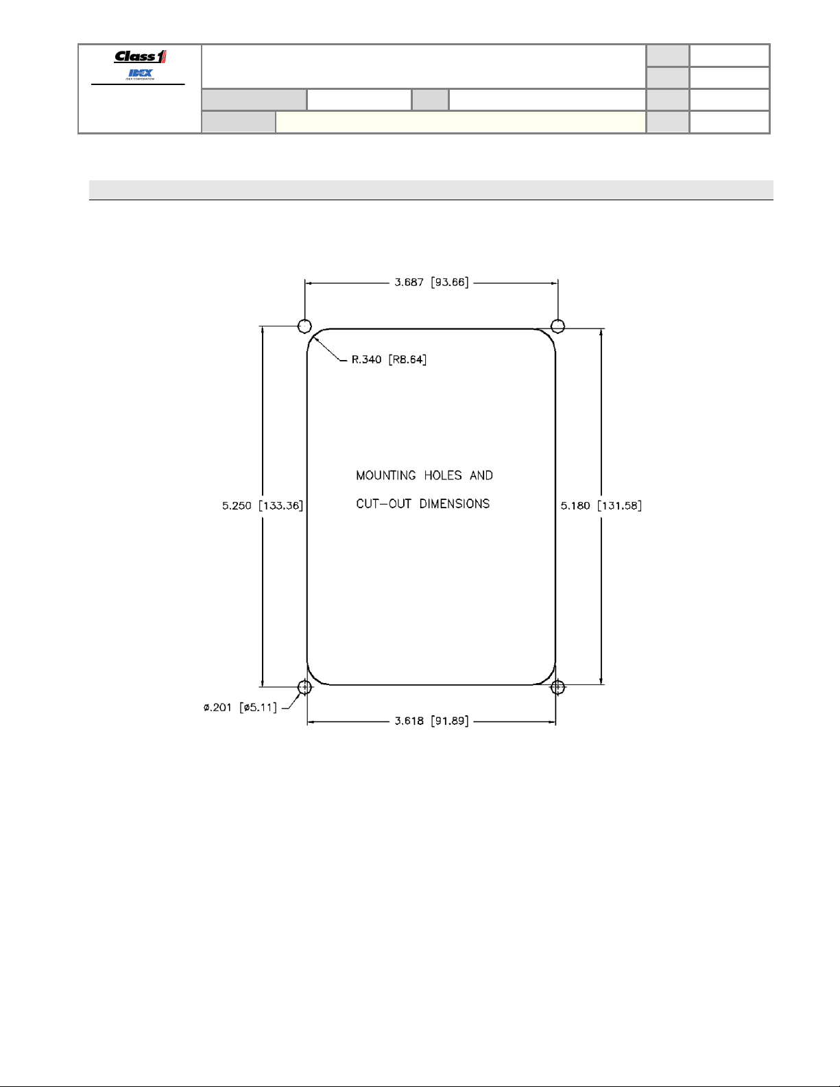
8. Mounting & installation
8.1. Panel cutout dimensions
TECHNICAL DATA SHEET
THROTTLE CONTROL
TOTAL PRESSURE GOVERNOR (TPG)
P/N 117155 REV
PAGE
DATE
BY AMS
27 OF 26
3/28/2012
1.23
Manual P/N 117684
Figure 5. Installation dimensions in inches [millimeters].
Page 29

FORM-ENG-0018 REV A 05-27-03
Mating connector: Deutsch DT06-6SA GRAY
PIN
CIRCUIT
DESCRIPTION
1
SUPPLY (+)
(
) – battery voltage
3
ALARM (-)
(OUTPUT) – alarm active
4
CAN HIGH
(
) – SAE J1939 CAN 2.0B, 250Kbits/s *
6
CAN SHIELD
(DATA) – SAE J1939 CAN 2.0B, 250Kbit s/s *
Mating connector: Deutsch DT06-12SA GRAY
PIN
CIRCUIT
DESCRIPTION
2
THROT INTLK
(INPUT) – throttle ready interlock
3
HI IDLE
(
) – high idle enable
4
OKAY TO PUMP
(
) – okay to pump interlock
5
Sensor GND
(OUTPUT) – pressure sensor ground
6
Sensor REF
(OUTPUT) – pressure sensor supply
7
Sensor SIGNAL
(
) – pressure sensor signal
8
ENG SIGNAL
(OUTPUT) – analog signal control (+0.5VDC to +4.5VDC) *
9
ENG REF (-)
(INPUT) – analog signal reference
10
PUMP INTLK
(
) – pump engaged interlock
12
RELAY N.O.
(OUTPUT) – remote throttle activate
Mating connector: Packard 12078090
PIN
CIRCUIT
DESCRIPTION
A
SUPPLY (-)
(INPUT) – pressure sensor ground
B
SUPPLY (+)
(
) – pressure sensor supply
C
Signal
(
) – pressure sensor signal
607 NW 27th Ave
Ocala, FL 34475
Ph: 352-629-5020 or 1-800-533-3569
Fax : 352-629-2902 or 1-800-520-3473
PRODUCT GROUP
PRODUCT
9. Connector Description
9.1. TPG connectors
The module has two connectors and the following definitions apply:
TECHNICAL DATA SHEET
THROTTLE CONTROL
TOTAL PRESSURE GOVERNOR (TPG)
P/N 117155 REV
PAGE
DATE
BY AMS
28 OF 26
3/28/2012
1.23
Mating sockets: Deutsch 0462-201-16141
Gold mating sockets: Deutsch 0462-201-1631
Wedge lock: W6S Recommended wire gage: 16-18 AWG
INPUT
(+9VDC…+32VDC)
2 SUPPLY (-) (INPUT) – battery ground
DATA
(ground polarity, 250mA)
5 CAN LOW (DATA) – SAE J1939 CAN 2.0B, 250Kbits/s *
* Gold pins recommended for CAN connections.
Mating sockets: Deutsch 0462-201-16141
Wedge lock: W12S Recommended wire gage: 16-18 AWG
1 ENG REF (+) (INPUT) – analog signal reference (+5VDC) *
INPUT
INPUT
INPUT
INPUT
11 RELAY COM (INPUT) – remote throttle (ground polarity) *
(positive polarity)
(positive polarity)
(positive polarity)
(+5VDC)
(+0.5VDC to +4.5VDC)
(ground) *
(positive polarity)
(ground polarity) *
(1)
* These pins and wires are avai labl e w ith th e anal og si gn al har ness (p/n 117683)
1
This input must be configured for operation – see section 5.2.34
9.2. Pressure sensor connector
The pressure sensor has one connector and the following definitions apply:
Mating sockets: Packard 12089290
Recom mended wire gage: 16-18 AW G
Manual P/N 117684
INPUT
OUTPUT
(+5VDC)
(+0.5VDC to +4.5VDC)
Page 30
FORM-ENG-0018 REV A 05-27-03
Product category
Throttle Control
Power consumption
Logic supply+ input (pin 1 of the 6-pin Deutsch connector)
Output power
Operational temperature range
-40ºC…+85ºC
Environmental range
IP 67
CAN specification
SAE CAN 2.0B J1939 , 250 Kbits/second (engine, transmission)
Internal thermal fuse (1850mA on pin 1 of the 6-pin Deutsch connector)
Dimensions (W x H x D) in inches [mm]
4.437 [112.70] x 6.000 [152.39] x 2.250 [57.15]
607 NW 27th Ave
Ocala, FL 34475
Ph: 352-629-5020 or 1-800-533-3569
Fax : 352-629-2902 or 1-800-520-3473
PRODUCT GROUP
PRODUCT
TECHNICAL DATA SHEET
THROTTLE CONTROL
TOTAL PRESSURE GOVERNOR (TPG)
10. Module Operating Parameters
Voltage range +9VDC…+32VDC
PAGE
DATE
P/N 117155 REV
BY AMS
29 OF 26
3/28/2012
1.23
@13.8VDC
@27.6VDC
Alarm
Protection
350mA
195mA
250mA (ground polarity)
Reverse voltage protection (pins 1 and 2 of the 6-pin Deutsch connector)
CAN buses protected to 24V
ESD voltage protected to SAE J1113 specification for heavy duty trucks (24V)
Transient voltage protected to SAE J1113 specification for heavy duty trucks (24V)
Load dump voltage protected to SAE J1113 specification for heavy duty trucks (24V)
Outputs protected for short circuit and thermal overload
Manual P/N 117684
 Loading...