

Page 1
ISO 9001 CERTIFIED
607 NW 27th Ave
Phone: (352) 629-5020 or 800-533-3569
Ocala, FL 34475
Fax: (352)-629-2902
OPERATION MANUAL
Total System Manager
Page 2

FORM-ENG-0018 REV A 05-27-03
607 NW 27th Ave
Ocala, FL 34475
Ph: 352-629-5020 or 1-800-533-3569
Fax : 352-629-2902 or 1-800-520-3473
PAGE
OPERATION MANUAL
PRODUCT GROUP System Manager P/N 610-00015 REV 1.01
PRODUCT
Total System Manager
DATE 03/01/2013
BY GMC
1 of 18
1.
REVISION LOG ........................................................................................................................................... 3
2. SYSTEM OVERVIEW .................................................................................................................................. 4
2.1. SCOPE .................................................................................................................................................... 4
2.2. FEATURES ............................................................................................................................................... 4
3. OPERATIONAL DATA ................................................................................................................................ 5
3.1. 12 VOLT SYSTEM. .................................................................................................................................... 5
3.2. 24 VOLT SYSTEM. .................................................................................................................................... 5
3.3. SEQUENCING. .......................................................................................................................................... 5
3.4. SHEDDING. .............................................................................................................................................. 5
3.5. FAST DLE. ................................................................................................................................................ 5
3.6. LOW VOLTAGE ALARM. ............................................................................................................................. 6
3.7. SWITCH SOURCES. ................................................................................................................................... 6
3.8. USER SETPOINT / VARIABLE TRIP. ............................................................................................................. 6
3.9. AUXILIARY BATTERY MONITORING. ............................................................................................................ 6
3.10. OUTPUT MODES. ...................................................................................................................................... 6
3.11. OUTPUT POLARITY. .................................................................................................................................. 6
3.12. OPERATING VOLTAGE. .............................................................................................................................. 6
3.13. OUTPUTS. ................................................................................................................................................ 6
3.14. TRANSIENT PROTECTION. ......................................................................................................................... 6
3.15. OVERRIDE. .............................................................................................................................................. 7
3.16. CAN. ...................................................................................................................................................... 7
4. PROGRAMMING ......................................................................................................................................... 7
4.1. PROGRAM MENU. ..................................................................................................................................... 7
4.2. PROGRAM SWITCH. .................................................................................................................................. 7
4.3. NEXT SWITCH. ......................................................................................................................................... 8
4.4. PRIORITY SWITCH. ................................................................................................................................... 8
4.5. ACTIVE SWITCH. ...................................................................................................................................... 8
4.6. MODE SWITCH. ........................................................................................................................................ 8
4.7. USER SWITCH. ......................................................................................................................................... 8
4.8. STORE SWITCH. ....................................................................................................................................... 8
4.9. INPUT OUTPUT POLARITY. ........................................................................................................................ 9
4.10. SYSTEM VOLTAGE SELECTION. ................................................................................................................. 9
5. PROGRAMMING EXAMPLE ..................................................................................................................... 10
5.1. PROGRAMMING EXAMPLE ....................................................................................................................... 10
6. CONNECTOR INFORMATION .................................................................................................................. 10
6.1. TERMINAL FUNCTION AND POLARITY ....................................................................................................... 10
7. DEFAULT SETTINGS ................................................................................................................................ 11
7.1. DEFAULTS. ............................................................................................................................................ 11
8. LEGACY SETTINGS ................................................................................................................................. 12
8.1. HISTORY. ............................................................................................................................................... 12
8.2. 101490. ................................................................................................................................................ 12
8.3. 101540. ................................................................................................................................................ 12
8.4. 101750. ................................................................................................................................................ 12
9. INSTALLATION ......................................................................................................................................... 13
DATASHEET P/N:FSG-MNL-00103 - UNCONTROLLED IN PRINTED FORMAT - PRINTED: 4/2/14
Page 3

FORM-ENG-0018 REV A 05-27-03
607 NW 27th Ave
Ocala, FL 34475
Ph: 352-629-5020 or 1-800-533-3569
Fax : 352-629-2902 or 1-800-520-3473
PAGE
OPERATION MANUAL
PRODUCT GROUP System Manager P/N 610-00015 REV 1.01
PRODUCT
Total System Manager
DATE 03/01/2013
BY GMC
2 of 18
9.1. MOUNTING DIMENSIONS .......................................................................................................................... 13
10. EXAMPLE INSTALLATIONS .................................................................................................................... 14
10.1. EXAMPLE. .............................................................................................................................................. 14
11. DEVICE NETWORK TX CAN MESSAGES .............................................................................................. 17
11.1. SOFTWARE VERSION MESSAGE (ES-KEY DESIGNATION 0X9A TO 0XFF) .................................................... 17
11.2. OUTPUT STATES MESSAGE (ES-KEY DESIGNATION 0X9A TO 0X9B) ......................................................... 17
11.3. INPUT STATES MESSAGE (ES-KEY DESIGNATION 0X9A TO 0X9C) ............................................................. 17
12. TECHNICAL DETAILS .............................................................................................................................. 18
12.1. TECHNICAL DETAILS ............................................................................................................................... 18
DATASHEET P/N:FSG-MNL-00103 - UNCONTROLLED IN PRINTED FORMAT - PRINTED: 4/2/14
Page 4

FORM-ENG-0018 REV A 05-27-03
607 NW 27th Ave
Ocala, FL 34475
Ph: 352-629-5020 or 1-800-533-3569
Fax : 352-629-2902 or 1-800-520-3473
1. Revision Log
Rev Date Approved Changes
1.01 4-02-2014 MH Corrected part number for 101750 configuration and added PCB drawing to technical details section.
1.00 3-01-2013 GMC Initial requirements
PAGE
OPERATION MANUAL
PRODUCT GROUP System Manager P/N 610-00015 REV 1.01
PRODUCT
Total System Manager
DATE 03/01/2013
BY GMC
3 of 18
DATASHEET P/N:FSG-MNL-00103 - UNCONTROLLED IN PRINTED FORMAT - PRINTED: 4/2/14
Page 5

FORM-ENG-0018 REV A 05-27-03
607 NW 27th Ave
Ocala, FL 34475
Ph: 352-629-5020 or 1-800-533-3569
Fax : 352-629-2902 or 1-800-520-3473
PRODUCT GROUP System Manager P/N 610-00015 REV 1.01
PRODUCT
2. System Overview
2.1. Scope
The Total System Manager provides a highly flexible electrical load management system that is user programmable
for each load output.
2.2. Features
Total System Manager C1 – p/n 610-00015
12 and 24 volt Selectable Operation.
Main Battery Monitoring.
Auxiliary Battery Monitoring.
Electrical Load Shedding.
Electrical Load Sequencing.
Reverse Polarity / Short Circuit Protection.
Sixteen Available Outputs.
Priorities can be set for Individual Loads.
Each load can be tied to Response and/or Scene Mode.
Individual loads can be configured to the Ignition or Master Warning Switch.
Dedicated output for a Fast Idle Function.
Low Voltage Alarm Output for main Battery (NFPA 1901).
Low voltage Alarm Output for Auxiliary Battery.
Variable Trip 'User Selectable' Output Selectable 10.5 to 15 VDC and 21 to 29 VDC.
Master, Park Brake, and Load Manage Enable Switch polarity selectable.
Digital Display shows System Voltage in Normal Operation.
Digital Display shows Configuration Information while in Program Mode.
Default Configurations can be restored at any time.
Polarity Selectable Outputs .250 AMPS
OPERATION MANUAL
Total System Manager
PAGE
DATE 03/01/2013
BY GMC
4 of 18
DATASHEET P/N:FSG-MNL-00103 - UNCONTROLLED IN PRINTED FORMAT - PRINTED: 4/2/14
Page 6

FORM-ENG-0018 REV A 05-27-03
607 NW 27th Ave
Ocala, FL 34475
Ph: 352-629-5020 or 1-800-533-3569
Fax : 352-629-2902 or 1-800-520-3473
PRODUCT GROUP System Manager P/N 610-00015 REV 1.01
PRODUCT
3. Operational Data
3.1. 12 Volt System.
SHED POINTS UNSHED POINTS
Level 0 Never Shed Level 1 11.4 Volts
Level 1 11.0 Volts Level 2 11.6 Volts
Level 2 11.4 Volts Level 3 12.0 Volts
Level 3 11.8 Volts Level 4 12.2 Volts
Level 4 12.0 Volts Level 5 12.4 Volts
Level 5 12.2 Volts Level 6 12.6 Volts
Level 6 12.4 Volts Level 7 12.8 Volts
Level 7 12.6 Volts Level 8 13.0 Volts
Level 8 12.7 Volts
3.2. 24 Volt System.
SHED POINTS UNSHED POINTS
Level 0 Never Shed Level 1 22.8 Volts
Level 1 22.0 Volts Level 2 23.6 Volts
Level 2 22.8 Volts Level 3 24.0 Volts
Level 3 23.6 Volts Level 4 24.4 Volts
Level 4 24.0 Volts Level 5 24.8 Volts
Level 5 24.4 Volts Level 6 25.2 Volts
Level 6 24.8 Volts Level 7 25.6 Volts
Level 7 25.2 Volts Level 8 26.0 Volts
Level 8 25.4 Volts
3.3. Sequencing.
Electrical loads will turn on sequentially in priority order form 1 to 8 when their respective switch is activated (either
ignition or warning master) and the vehicle is operated in the mode selected for that output (response and/or scene).
loads will sequence off in the reverse order. Priority zero loads will be sequenced on and off but will not shed.
3.4. Shedding.
Electrical loads will be turned off (shed) when the system voltage drops to the shed point for a minimum of 1 minute
(this prevents load shedding due to momentary system power loading such as high current start up devices). Once
shed, loads will remain off for a minimum of 5 minutes and until the unshed voltage is achieved for a minimum of 1
minute. Loads will only shed if the Parking Brake is set and the Load Manage Enable input is active.
3.5. Fast dle.
A fast idle output is activated whenever the system voltage is reduced to 12.8 volts on a 12 volt system or 25.6 volts
on a 24 volt system for a least one minute. The fast idle will remain ON for a minimum of 10 minutes and until 13.0
volts on a 12 volt system or 26 volts on a 24 volt system is achieved. The fast idle output is dependent on the Parking
Brake and Load Manage Enable Input.
Note:
1. This output should only be us ed as part of a fast idle control system when the proper safety interlocks are
present.
2. The FAST IDLE output will turn off immediately when the Load Manage Enable Input is disengaged.
OPERATION MANUAL
Total System Manager
PAGE
DATE 03/01/2013
BY GMC
5 of 18
DATASHEET P/N:FSG-MNL-00103 - UNCONTROLLED IN PRINTED FORMAT - PRINTED: 4/2/14
Page 7

FORM-ENG-0018 REV A 05-27-03
607 NW 27th Ave
Ocala, FL 34475
Ph: 352-629-5020 or 1-800-533-3569
Fax : 352-629-2902 or 1-800-520-3473
3.6. Low Voltage Alarm.
Whenever the system voltage drops below 11.9 volts for a 12 volt system or 23.8 volts for a 24 volt system a low
voltage alarm output is activated. This complies with the N.F.P.A. 1901 requirements.
3.7. Switch Sources.
Each load can be programmed to activate by either the Ignition switch or the Warning Master switch.
Ignition: Loads programmed for ignition will sequence on when the vehicle ignition switch is turned ON.
Warning Master: Loads programmed for master warning will sequence on when the master warning switch is turned
ON.
3.8. User Setpoint / Variable Trip.
This is the user definable output. The user has the option of selecting a 'trip' voltage between 10.5 and 14 .5 volts for a
12 volt system or between 21.0 and 29.0 volts for a 24 volt system. If the trip point is set to 13.8 volts or above on a
12 volt system or set to 27.6 volts or above on a 24 volt system the output acts as an overvoltage indicator and will
turn on when the selected voltage is reached. If the 'trip' voltage is set below 13.8 volts for a 12 volt system or 27.6
volts for a 24 volt system the output will activate when the voltage drops to the setpoint.
3.9. Auxiliary Battery Monitoring.
Terminal #23 can be used to monitor an auxiliary battery. There should be no connections to this terminal if a remote
battery is not monitored. If the auxiliary battery voltage drops below 11.9 volts on a 12 volt system or 23.8 volts on a
24 volt system the auxiliary battery output will turn on.
3.10. Output Modes.
Each load can be programmed for RESPONSE MODE, SCENE MODE, OR BOTH.
Response Mode: The output is ON only when the Park Brake is NOT set.
Scene Mode: The output is ON only when the Park Brake IS set.
Both: The output is ON in both Response and Scene Mode.
3.11. Output Polarity.
All Outputs can be user selected to operate as a High Side or Low side Output.
3.12. Operating voltage.
The unit will operate from 7 to 32 volts DC.
3.13. Outputs.
Every output is user selectable to be a High side or a Low Side driver.
High Side: Vmain at 0.5 amp (source).
Low Side: Ground at 0.5 amp (sink).
3.14. Transient protection.
The main power supply and all outputs are protected against direct shorts and transi ent spikes.
PRODUCT GROUP System Manager P/N 610-00015 REV 1.01
PRODUCT
Total System Manager
OPERATION MANUAL
PAGE
DATE 03/01/2013
BY GMC
6 of 18
DATASHEET P/N:FSG-MNL-00103 - UNCONTROLLED IN PRINTED FORMAT - PRINTED: 4/2/14
Page 8

FORM-ENG-0018 REV A 05-27-03
607 NW 27th Ave
Ocala, FL 34475
Ph: 352-629-5020 or 1-800-533-3569
Fax : 352-629-2902 or 1-800-520-3473
PAGE
OPERATION MANUAL
PRODUCT GROUP System Manager P/N 610-00015 REV 1.01
PRODUCT
Total System Manager
DATE 03/01/2013
BY GMC
7 of 18
3.15. Override.
When the Override switch is activated Outputs 1 through 12 will turn on no matter what state they currently operating
in. The Override LED will flash at a 500mS rate to indicate that the Override feature has been activated. Caution
should be paid attention to the Override feature is intended for quickly turning on all Output loads in time of need. If
used to verify that the outputs work in a trouble shooting capacity if the corresponding output LED is turned on and
the load attached to the output does not turn on check for a short or proper output polarity.
3.16. CAN.
The unit transmits the output states and input states VIA CAN (Control Area Network) utilizing the SAE J1939
proprietary, 250 Kbits/second protocol. See section 9 for more information.
4. Programming
4.1. Program Menu.
Programming the Total System Manager is accomplished using push button switches and a straightforward menu
approach. A digital display and 4 LED's provide feedback to the programmer.
4.2. Program Switch.
The program switch has three modes.
Mode 1:
If you press and hold the USER switch and then press the PROG switch this will place the unit into program mode
indicated by displaying 3 dashes (---) on the digital display and the displaying L01.
Mode 2:
If you press and hold the USER switch and then press the PROG switch. Continue to hold the PROG switch for
(aprox. 10 seconds) will load the factory defaults. Indicated by displaying dEF on the digital display.
Mode 3:
When the unit is in program mode holding the PROG switch will save the new values. Indicated by displaying Pro on
the digital display.
DATASHEET P/N:FSG-MNL-00103 - UNCONTROLLED IN PRINTED FORMAT - PRINTED: 4/2/14
Page 9

FORM-ENG-0018 REV A 05-27-03
607 NW 27th Ave
Ocala, FL 34475
Ph: 352-629-5020 or 1-800-533-3569
Fax : 352-629-2902 or 1-800-520-3473
4.3. Next Switch.
Pressing the NEXT switch while in program mode will cycle through each output, The Output LOAD LED will turn on
for the active output and the digital display will indicate the load selected by displayi ng L01-L13.
4.4. Priority Switch.
The PRIORITY switch selects the sequence and shed priority level for the selected output. The digital display will
show the current priority as the switch cycles through from P00 to P08. Loads sequence on in priority from 1 to 8 and
they shed off in priority from 8 to 1. loads set to priority 0 will never shed but they will sequence on and off.
4.5. Active Switch.
The ACTIVE switch toggles the switch source either ignition or warning master for the selected output.
IGNITION LED: Output is tied to the Ignition switch.
WRN MASTER LED: Output is tied to the master switch.
4.6. Mode Switch.
The MODE switch toggles through the available modes for load management.
RESPONSE LED: Output in ON only when the Parking Brake is NOT set.
SCENE LED: Output is ON only when the Parking brake IS set.
BOTH LED: Output is on regardless of the Parking Brake status.
4.7. User Switch.
The USER switch adjust the setpoint voltage for output #13 (term 19). Pressing the button increases the 'trip' point in
0.1 volt increments from 10.5 volts to 14.5 volts for a 12 volt system and 21 volts to 29 volts for a 24 volt system. If the
trip point is set to 13.8 volts or above on a 12 volt system or set to 27.6 volts or above on a 24 volt system the output
acts as an overvoltage indicator and will turn on when the selected voltage is reached. If the 'trip' voltage is set below
13.8 volts for a 12 volt system or 27.6 volts for a 24 volt system the output will activate when the voltage drops to the
setpoint.
4.8. Store Switch.
The STORE switch saves the current configuration for the selected output. The display will indicate that the value has
been saved by showing 3 dashes (---) and then the load number (Lxx) on the digital displa y.
PAGE
OPERATION MANUAL
PRODUCT GROUP System Manager P/N 610-00015 REV 1.01
PRODUCT
Total System Manager
DATE 03/01/2013
BY GMC
8 of 18
DATASHEET P/N:FSG-MNL-00103 - UNCONTROLLED IN PRINTED FORMAT - PRINTED: 4/2/14
Page 10

FORM-ENG-0018 REV A 05-27-03
607 NW 27th Ave
Ocala, FL 34475
Ph: 352-629-5020 or 1-800-533-3569
Fax : 352-629-2902 or 1-800-520-3473
4.9. Input Output Polarity.
PRODUCT GROUP System Manager P/N 610-00015 REV 1.01
PRODUCT
OPERATION MANUAL
Total System Manager
PAGE
DATE 03/01/2013
BY GMC
9 of 18
The output polarity switches control the output polarity for loads 1 through 16. The polarity of the outputs is set on
power up of the unit. changes to the polarity switches will not take place until the next power c ycle. Caution should be
taken to make sure the polarity is selected correctly for the individual output based on the load it is attached to.
The input polarity shunts control the polarity for Master Warning, Park Brake, and Load Manage Enable inputs.
4.10. System Voltage selection.
When the unit is in programming mode press the NEXT switch until the digital display reads either -12 or -24 (the
default setting is -12). Selecting the USER switch will change between -12 or -24. Once the desired setting has been
selected press the STORE switch until 3 dashes (---) are displayed on the digital display. Press and hold the PROG
switch until Pro appears on the digital display this will indicate the setting has been saved.
DATASHEET P/N:FSG-MNL-00103 - UNCONTROLLED IN PRINTED FORMAT - PRINTED: 4/2/14
Page 11

FORM-ENG-0018 REV A 05-27-03
607 NW 27th Ave
Ocala, FL 34475
Ph: 352-629-5020 or 1-800-533-3569
Fax : 352-629-2902 or 1-800-520-3473
PRODUCT GROUP System Manager P/N 610-00015 REV 1.01
PRODUCT
Total System Manager
5. Programming Example
5.1. Programming Example
You want load #3 to shed at a voltage level of 12.0 volts. It needs to be tied to the Master Switch and be activated in
the Scene Mode.
1. Depress the USER and PROG switches until (---) is displayed.
2. Press the NEXT switch until L03 is displayed on the digital display.
3. Press the MODE switch until only the SCENE LED is on.
4. Press the ACTIVE switch until only the WRM MASTER LED is on.
5. Press the PRIORITY switch until P04 is displayed on the digital display.
6. Press the STORE switch until 3 dashes (---) are displayed on the digital display.
7. If you want to configure another output select the NEXT s witch and repeat the procedure to program that
output.
8. When all the outputs are programmed press and hold PROG switch until Pro is displayed on the digital
display.
Note: If you do not press the STORE switch after each Output is configured that Output will not be changed.
6. Connector Information
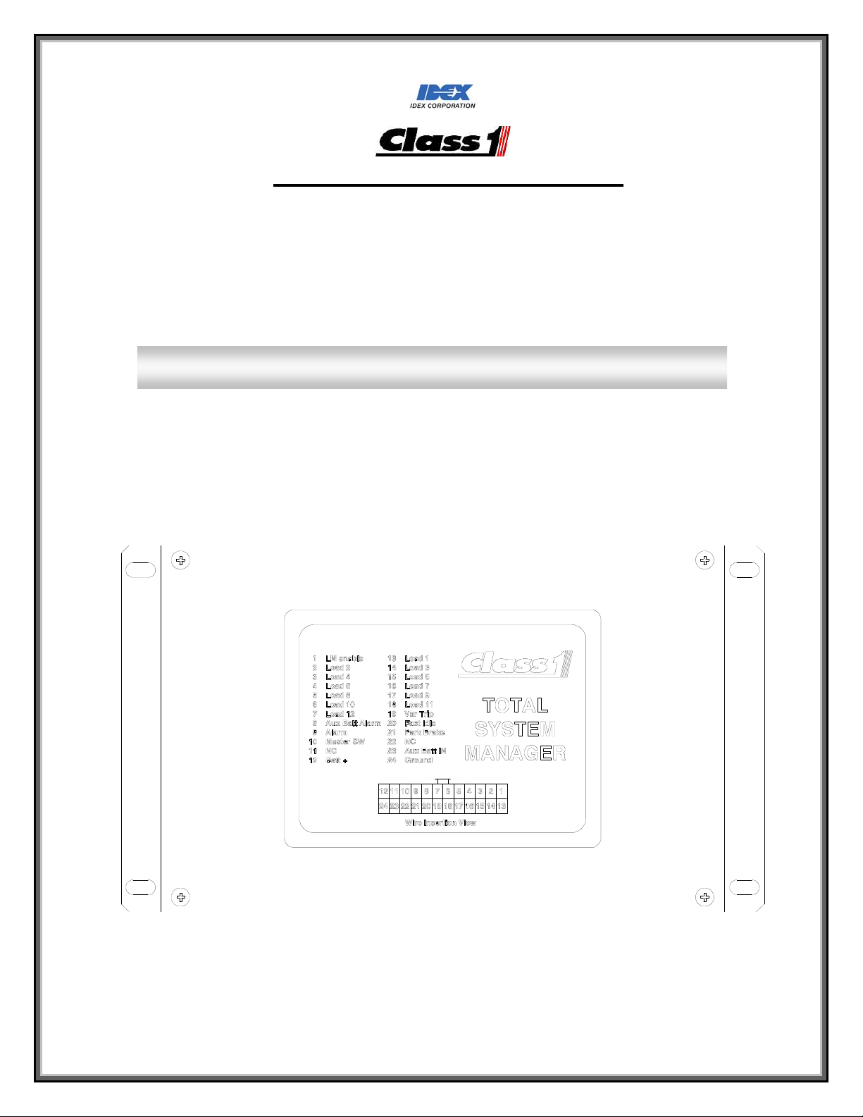
6.1. Terminal Function and Polarity
Terminal Function Polarity Terminal Function Polarity
1 Load Manage Enable POS/GND 13 Output Load # 1 POS/GND
2 Output Loa d # 2 POS/GND 14 Output Load # 3 POS/GND
3 Output Loa d # 4 POS/GND 15 Output Load # 5 POS/GND
4 Output Loa d # 6 POS/GND 16 Output Load # 7 POS/GND
5 Output Loa d # 8 POS/GND 17 Output Load # 9 POS/GND
6 Output Loa d # 10 POS/GND 18 Output Load # 11 POS/GND
7 Output Loa d # 12 POS/GND 19 VAR Trip Output POS/GND
8 AUX Batter y Alarm POS/GND 20 Output Fast Idle POS/GND
9 Low Voltage Alarm POS/GND 21 Parking Brake Input POS/GND
10 Master Switch Input POS/GND 22 CAN LOW N/A
11 CAN HIGH N/A 23 Aux Battery Input Positive
12 Main Battery Power Positive 24 Ground Ground
Mating connector AMP 770587-1
Socket(Loose Form) AMP 171639-1 16-18 Ga
Socket(Strip form) AMP 171637-1 16-18 Ga
Crimping Tool AMP 90760-1 Pro Crimper
Contact Extraction Tool AMP 189727-1
Connector and Socket Kit Class1 P.N. 101536
Mating Pigtail Class1 P.N. 101538
The Main battery power (term #12) and ground (term #24) should be wired direct to the battery as possible.
OPERATION MANUAL
PAGE
DATE 03/01/2013
BY GMC
10 of 18
DATASHEET P/N:FSG-MNL-00103 - UNCONTROLLED IN PRINTED FORMAT - PRINTED: 4/2/14
Page 12

FORM-ENG-0018 REV A 05-27-03
607 NW 27th Ave
Ocala, FL 34475
Ph: 352-629-5020 or 1-800-533-3569
Fax : 352-629-2902 or 1-800-520-3473
PRODUCT GROUP System Manager P/N 610-00015 REV 1.01
PRODUCT
7. Default Settings
7.1. Defaults.
The Total System manager is shipped with the following default settings.
Priority Shed Point UnShed Point
8 12.7 13.0
7 12.6 12.8
6 12.4 12.6
5 12.2 12.4
4 12.0 12.2
3 11.8 12.0
2 11.4 11.6
1 11.0 11.4
Unit is set to work for a 12 volt system
Loads 1 through 8 are set to priority 1 through 8 respectively and are tied to the Master Warning Switch. These loads
will sequence on 1 through 8 and sequence off 8 through 1. They will shed 8 through 1 when the system voltage falls
to the shed point for that priority level.
Loads 9 through 12 are set to priority zero and come on with the ignition switch. These loads will sequence on and off
but will not shed due to voltage.
Load 1 through 12 are configured to BOTH modes SCENE and RESPONSE. The default polarity for outputs 1
through 12 is positive.
Load 13 is the user configurable Output. The default polarity setting output 13 is positive. The default setting for the
'Variable Trip' Point is 14.5 volts.
Load 14 is the AUXILIARY Battery Alarm. The default polarity setting output 14 is positive.
Load 15 is the Fast Idle Output. The default polarity setting for output 15 is positive. This load becomes active when
the system voltage drops to 12.8 volts.
Load 16 is the Low Voltage Alarm Output. The default polarity for output 16 is negative. This load becomes active
when the system voltage drops below 11.9 volts.
The default polarity for the Master Warning Input, Park Brake Input, and Load Manage Enable input is negative.
OPERATION MANUAL
Total System Manager
PAGE
DATE 03/01/2013
BY GMC
11 of 18
DATASHEET P/N:FSG-MNL-00103 - UNCONTROLLED IN PRINTED FORMAT - PRINTED: 4/2/14
Page 13

FORM-ENG-0018 REV A 05-27-03
607 NW 27th Ave
Ocala, FL 34475
Ph: 352-629-5020 or 1-800-533-3569
Fax : 352-629-2902 or 1-800-520-3473
PRODUCT GROUP System Manager P/N 610-00015 REV 1.01
PRODUCT
8. Legacy Settings
8.1. History.
The Total System Manager historically was shipped under different part numbers. 101490, 101540, and 101750. The
101490 had positive outputs for loads 1-12 and the 101540 and 101750 had negative outputs for loads 1-12. If
replacing either of these part number use the following setup configurations.
8.2. 101490.
Two configure the unit to work as the 101490 use the following configuration.
Set the Input polarity shunts to the negative position.
Set the Output polarity switch 1-12 to the positive position.
Set the Output polarity switch A (Low voltage alarm) to the negative position.
Set the Output polarity switch I (Auxiliary Voltage alarm) to the positive position.
Set the Output polarity switch V (Variable Trip) to the positive position.
Set the Output polarity switch HI (High Idle) to the positive position.
Set the system voltage to 12 volts (see section 4.10).
8.3. 101540.
Two configure the unit to work as the 101540 use the following configuration.
Set the Input polarity shunts to the negative position.
Set the Output polarity switch 1-12 to the negative position.
Set the Output polarity switch A (Low voltage alarm) to the negative position.
Set the Output polarity switch I (Auxiliary Voltage alarm) to the positive position.
Set the Output polarity switch V (Variable Trip) to the positive position.
Set the Output polarity switch HI (High Idle) to the positive position.
Set the system voltage to 12 volts (see section 4.10).
8.4. 101750.
Two configure the unit to work as the 101750 use the following configuration.
Set the Input polarity shunts to the negative position.
Set the Output polarity switch 1-12 to the negative position.
Set the Output polarity switch A (Low voltage alarm) to the negative position.
Set the Output polarity switch I (Auxiliary Voltage alarm) to the positive position.
Set the Output polarity switch V (Variable Trip) to the positive position.
Set the Output polarity switch HI (High Idle) to the positive position.
Set the system voltage to 24 volts (see section 4.10).
OPERATION MANUAL
Total System Manager
PAGE
DATE 03/01/2013
BY GMC
12 of 18
DATASHEET P/N:FSG-MNL-00103 - UNCONTROLLED IN PRINTED FORMAT - PRINTED: 4/2/14
Page 14

FORM-ENG-0018 REV A 05-27-03
607 NW 27th Ave
Ocala, FL 34475
Ph: 352-629-5020 or 1-800-533-3569
Fax : 352-629-2902 or 1-800-520-3473
PRODUCT GROUP System Manager P/N 610-00015 REV 1.01
PRODUCT
9. Installation
9.1. Mounting dimensions
OPERATION MANUAL
Total System Manager
PAGE
DATE 03/01/2013
BY GMC
13 of 18
Unit of scale: inches
DATASHEET P/N:FSG-MNL-00103 - UNCONTROLLED IN PRINTED FORMAT - PRINTED: 4/2/14
Page 15
FORM-ENG-0018 REV A 05-27-03
607 NW 27th Ave
Ocala, FL 34475
Ph: 352-629-5020 or 1-800-533-3569
Fax : 352-629-2902 or 1-800-520-3473
PRODUCT GROUP System Manager P/N 610-00015 REV 1.01
PRODUCT
10. Example Installations
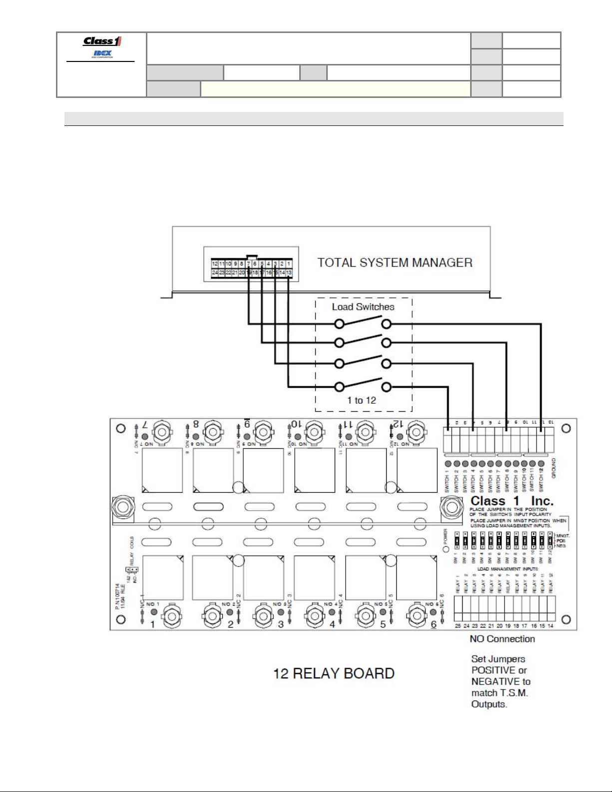
10.1. Example.
Connections to the vehicle electrical system can be simplified by using the Class1 12 relay board. Simply install the
cab loads switches in series between the Total System Manager and the 12 relay board switch inputs. This
installation allows the dash switches to illuminate only when a load is enabled, giving the operator a qui ck check of
the vehicles electrical system ready status.
OPERATION MANUAL
Total System Manager
PAGE
DATE 03/01/2013
BY GMC
14 of 18
DATASHEET P/N:FSG-MNL-00103 - UNCONTROLLED IN PRINTED FORMAT - PRINTED: 4/2/14
Page 16

FORM-ENG-0018 REV A 05-27-03
607 NW 27th Ave
Ocala, FL 34475
Ph: 352-629-5020 or 1-800-533-3569
Fax : 352-629-2902 or 1-800-520-3473
PAGE
OPERATION MANUAL
PRODUCT GROUP System Manager P/N 610-00015 REV 1.01
PRODUCT
Total System Manager
DATE 03/01/2013
BY GMC
15 of 18
DATASHEET P/N:FSG-MNL-00103 - UNCONTROLLED IN PRINTED FORMAT - PRINTED: 4/2/14
Page 17

FORM-ENG-0018 REV A 05-27-03
607 NW 27th Ave
Ocala, FL 34475
Ph: 352-629-5020 or 1-800-533-3569
Fax : 352-629-2902 or 1-800-520-3473
PAGE
OPERATION MANUAL
PRODUCT GROUP System Manager P/N 610-00015 REV 1.01
PRODUCT
Total System Manager
DATE 03/01/2013
BY GMC
16 of 18
DATASHEET P/N:FSG-MNL-00103 - UNCONTROLLED IN PRINTED FORMAT - PRINTED: 4/2/14
Page 18

FORM-ENG-0018 REV A 05-27-03
607 NW 27th Ave
Ocala, FL 34475
Ph: 352-629-5020 or 1-800-533-3569
Fax : 352-629-2902 or 1-800-520-3473
PAGE
OPERATION MANUAL
PRODUCT GROUP System Manager P/N 610-00015 REV 1.01
PRODUCT
Total System Manager
DATE 03/01/2013
BY GMC
17 of 18
11. Device Network TX CAN messages
11.1. Software version message (ES-Key designation 0x9A to 0xFF)
Priority: 6 Datapage: 0
PDU Format: 239 PDU Specific: 255
Source addr: 154 Message frequency: 10 per second
Byte 5 – Software version (high nibble = major rev, low nibble = minor rev)
11.2. Output States message (ES-Key designation 0x9A to 0x9B)
Priority: 6 Datapage: 0
PDU Format: 239 PDU Specific: 30
Source addr: 154 Message frequency: 10 per second
Byte 0 – Load 1 through Load 8 state (Load 0 is in the LSb position)
Byte 1 – Load 9 through Load 16 state (Load 9 is in the LSb position)
Byte 2 – System Voltage (Low Byte)
Byte 3 – System Voltage (High Byte)
Byte 4 – Iso Battery Voltage (Low Byte)
Byte 5 – Iso Battery Voltage (High Byte)
Byte 6 – User Set Point (Low Byte)
Byte 7 – User Set Point (High Byte)
11.3. Input States message (ES-Key designation 0x9A to 0x9C)
Priority: 6 Datapage: 0
PDU Format: 239 PDU Specific: 30
Source addr: 154 Message frequency: 10 per second
Byte 0 – Master Switch state (0x00 OFF 0x01 ON)
Byte 1 – Park Brake Switch state (0x00 OFF 0x01 ON)
Byte 2 – Load Manage Switch state (0x00 OFF 0x01 ON)
Byte 3 – System Voltage Mode (0x00 12 volt system 0x01 24 volt system)
Byte 4 – Override State (0x00 OFF 0x01 ON)
Byte 5 – Fast Mode (0x00 OFF 0x01 ON) used for factory testing
Byte 6 – 0x00
Byte 7 – 0x00
DATASHEET P/N:FSG-MNL-00103 - UNCONTROLLED IN PRINTED FORMAT - PRINTED: 4/2/14
Page 19

FORM-ENG-0018 REV A 05-27-03
607 NW 27th Ave
Ocala, FL 34475
Ph: 352-629-5020 or 1-800-533-3569
Fax : 352-629-2902 or 1-800-520-3473
PRODUCT GROUP System Manager P/N 610-00015 REV 1.01
12. Technical details
12.1. Technical details
Product category Load Managers
Voltage range +7VDC…+32VDC
Power consumption with no loads
@13.8VDC (25ºC)
@27.6VDC (25ºC)
Operational temperature range -40ºC…+85ºC
Environmental range IP 63 - IP 64 unit is conformal coated
CAN specification SAE J1939 proprietary, 250 Kbits/second
Protection
Dimensions (W x H x D) in inches [mm] 8.125 x 4.875 x 1.625
PRODUCT
OPERATION MANUAL
Total System Manager
125 mA
125 mA
Internal thermal fuse
Reverse voltage protection (pins 1 and 12 of connector)
CAN buses protected to 24V
ESD voltage protected to SAE J1113 specifications
Transient voltage protected to SAE J1113 specifications
PAGE
DATE 03/01/2013
BY GMC
18 of 18
DATASHEET P/N:FSG-MNL-00103 - UNCONTROLLED IN PRINTED FORMAT - PRINTED: 4/2/14
 Loading...