

Page 1

PTEC II
Pump Throttle Electronic Control
Series II
PTEC II PN 100509
For Mechanical Diesel Engines
1
Page 2

PTEC II
System Overview
The Series II Pressure Governor is a computer controlled throttle and pump interlock monitoring system. The system uses a linear throttle actuator and a set of toggle switches to control
engine RPM. It will maintain a selected pump discharge pressure or engine speed in response to the selected mode and desired operating parameter. Pressure sensing is done
with a 0-300 PSI transducer and RPM is monitored with a magnetic pick-up.
There are seven (7) major components:
ECU Microsentry Unit PN 108082
PSI Transducer PN 100581
Linear Actuator PN 101702
RPM Sensor PN 102902
Actuator Control Module PN 100328
Control Head PN 100478
Harness PN100454-D
In PSI Mode, the system monitors the pressure transducer and changes the actuator position
to maintain the set pressure. In essence, cruise control for the pump. In RPM Mode, the
system maintains a constant engine RPM regardless of varying torque loads or pressure.
Both modes are dependent on the capability of the engine to respond to changes.
The system has diagnostic capability through the Control Head Assembly and requires a
“diagnostic pigtail” for access. The system stores fault codes for key components and these
are also accessed through the Control Head.
Installation requirements are 12 Volt power with circuit protection and a safety interlock system.
2
Page 3

PTEC II
Hardware
Electronic Control Unit (ECU)
Microprocessor control logic to operate the system. The ECU contains internal memory for
system setup and diagnostic information. Inputs and outputs at the ECU determine system
operation. The ECU should be mounted in an accessible area but protected as much as
possible from physical damage especially the wiring.
P.E.D. # 12034398
CONN:
TERM:
P.E.D. # 12047680
SOCKET
CONN:
TERM:
SOCKET
WIRE
1B DEC
MAGPU
2B
3B INC
1C
DIAGNOSTIC
1E
INTLK #1A
GOVMODE
2E
PPSI
2G
PSI GND
3J
ACT IN/ON3K
P.E.D. # 12040921
P.E.D. # 12047680
WIRE
ACTOUT
3A
GOV LT
2C
GROUND
3D
1F SYS ACTIVE
5V-OUT
3F2FMAGGND
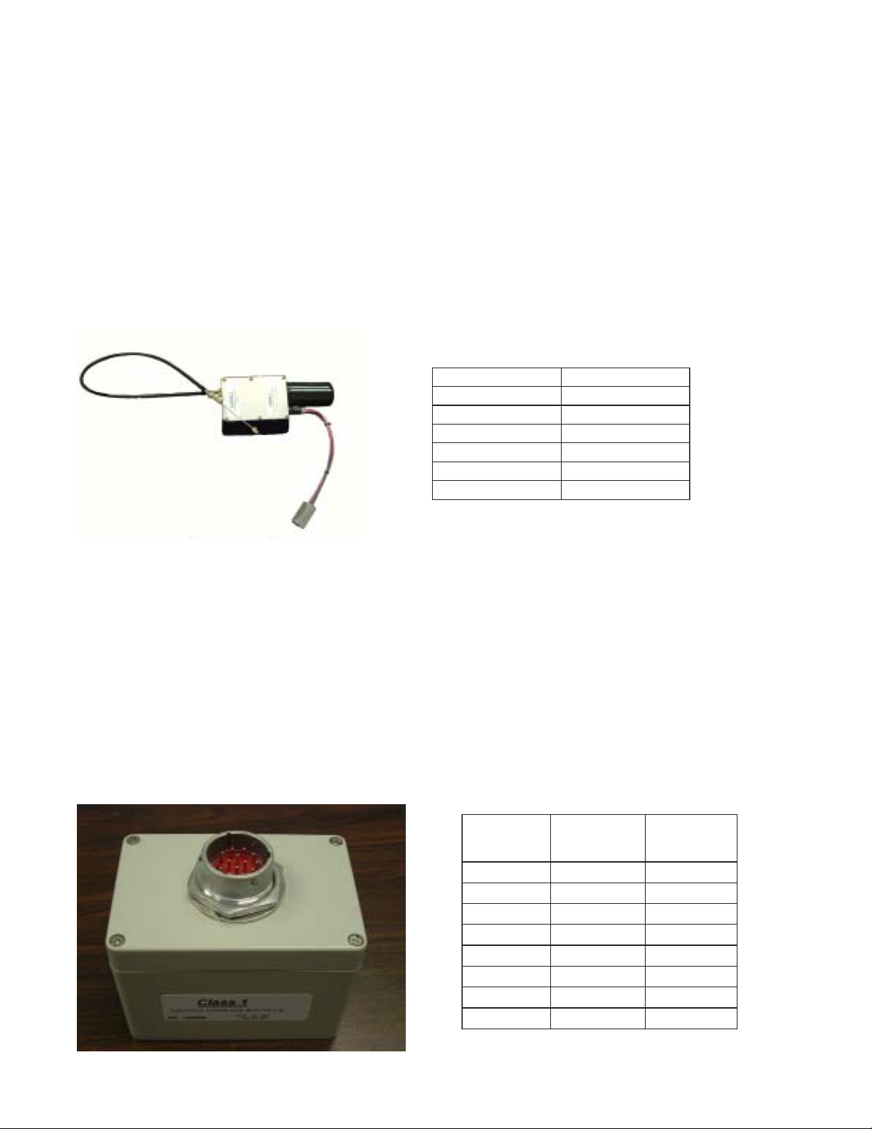
Control Head
This unit contains the switches and LED’s for the user interface to the system. Diagnostics
and System Setup can be performed using the Control Head and a diagnostic connector.
This part of the system is the operator interface and should be mounted on the pump panel at
a height that allows easy operation and viewing.
UCE
-41DHhcstueD
P61-9
LANIMRETTEKCOSNOITCNUF
----------A YDAERSYS
rotcennoC
F1-2C
E1-1C
----------
E2-1C
B3-1C
B1-1C
C2-2C
D3-2C
BEVITCASYS
CA1#KLTNI
D1#KLTNI
EEDOMVOG
FCNI
GCED
HTLVOG
JDNUORG
lanimreT
-0640hcstueD
14161-202
3
Page 4
PTEC II
Hardware (cont.)
Linear Actuator
This is a 12 VDC, 2 Amp nominal DC motor incorporating fast braking on direction change,
adjustable limits (max. 3 inch) and a high pull force (50 lbs). The resolution of the actuator
installation is perhaps the most critical of the system. The least RPM change with the greatest actuator movement possible works best.
The actuator should be mounted in an area that subjects it to least amount of vibration, heat
and water. The actuator body should be mounted higher than the linkage point to prevent
water intrusion through the cable.. It should NOT be mounted directly to the engine or engine
mounts or brackets.
ROTAUTCAROTCENNOC
TEKCOSNOITCNUF
A----------
B---------CDNUORG
DARIDTCA
EBRIDTCA
Vehicle Interface Box
The Actuator Interface Module connects to the harness with a Deutsch connector and is
sealed against the environment. It contains the relays for actuator direction and mechanical
force to idle. Anytime the Park Brake interlock is lost or the governor switch is turned of f, the
module disconnects the actuator from the ECU and forces it to Idle.
This is a sealed unit and can be mounted in any convenient location that provides protection
from physical damage.
ROTAUTCA
ECAFRETNI
UCETEKCOSNOITCNUF
A3-2CA TUOTCA
D3-2CE DNUORG
----------F+TTAB
E1-1CL A1#KLTNI
K3-1CM NONITCA
----------N BRIDTCA
----------P ARIDTCA
ROTCENNOC
HCSTUED
NS41-81-63DH
SLANIMRET
HCSTUED
14161-102-2640
4
Page 5
PTEC II
I
l
+12 VDC
Hardware (cont.)
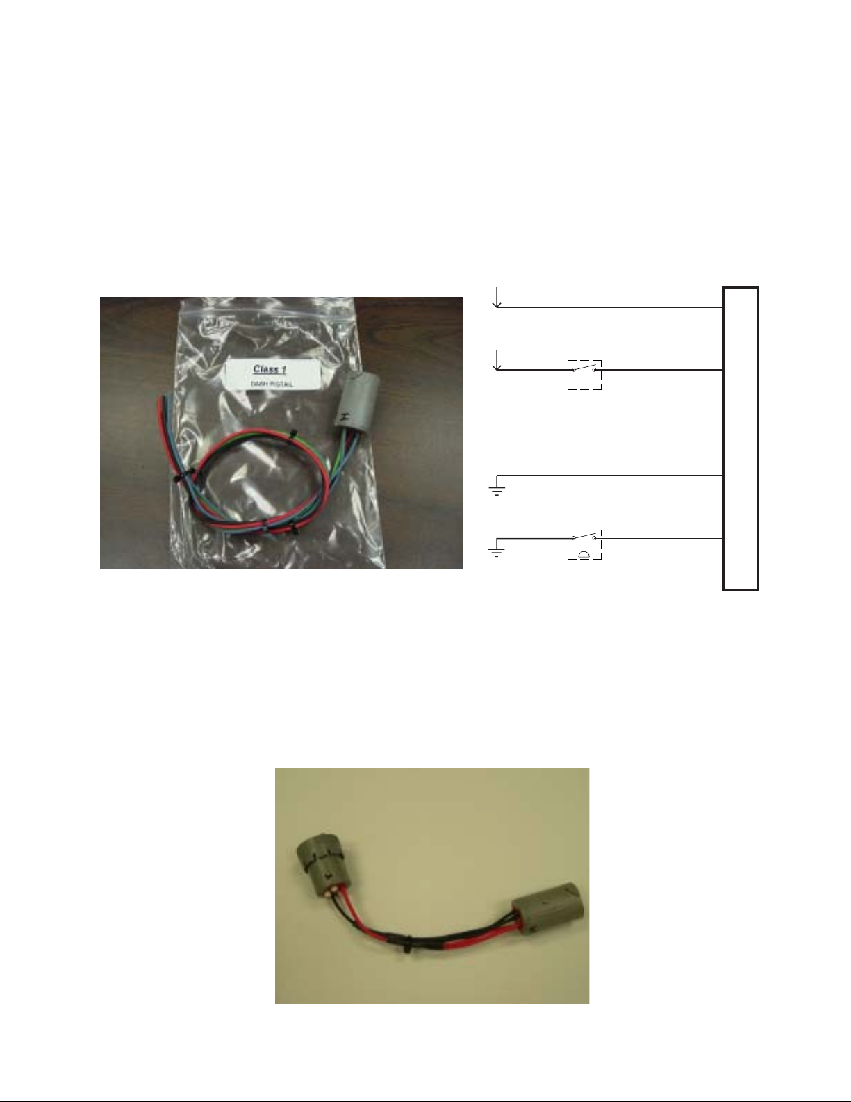
Dash Interlock Connections
System Power and Ground are connected to the harness through this connector . They should
be clean and as direct to the battery as possible. Two safety interlocks are connected to
system at this point. SYS READY, 12 VDC when Okay to Pump is achieved and INTLK#1
which is a ground typically when the Park Brake is set. INTLK #1 must be below 700mV to be
valid at the ECU.
+12 VDC
Okay to Pump
12 VDC Signal
Park Brake
Switch Ground
Batt +
Sys Ready
System Ground
Direct Battery
Interlock#1
A
D
a
s
h
B
n
t
e
r
o
c
k
D
C
o
n
n
e
c
E
t
o
r
The system diagnostic cable is placed between the Dash Interlock Connector and the Harness to facilitate set-up and diagnostics.
5
Page 6

PTEC II
Hardware (cont.)
Pressure Transducer
The transducer is a 300 PSI gauge pressure sensor. The PSI sensor is a voltage generator
based on pressure with a range of 4 volts DC starting at 700 mV atmospheric pressure. It is
connected to the harness with a 3 pin Packard Metri-pack connector and provided with a 5
VDC source and signal ground by the ECU. It should be mounted on the discharge side of
the pump. At the rear of the Pressure Test Port or Master Discharge Gauge is a desirable
location. The transducer is a critical component of the system that is the only piece that
provides pump pressure information to the ECU.
UCE
dnuorGISPJ3-1CAA
CDV5ISPF2-2CCB
langiSISPG2-1CBC
talF
rotcennoC
recudsnarT
rotcennoC
Speed Sensor
Magnetic Pickup type (13/16 NC thread) operating typically off the flywheel for pulse generation (frequency input to the ECU). It connects to the harness with a 2 pin Packard Weatherpack connector. It must be mounted to the bell housing where it is in close proximity to the
engine flywheel teeth.
6
rotcennoC
29751021drakcaP
UCEtekcoSeriW
B2-1CA UPgaM
F3-2CB dnGgaM
lanimreT
28101021drakcaP
Page 7

PTEC II
Linear Actuator
3" Stroke
2" Stroke
1"Stroke
Fuel Control Arm
The further out on the control arm that the actuator cable is installed,
the better the actuator resolution.
In most cases the fuel control arm needs to be extended to make best
use of the 3" actuator stroke.
Ideally, a small amount of actuator movement should result in very minor
changes in RPM.
If the actuator installation has poor resolution, the result will be uncontrollable
engine oscillations as the governor attempts to find the setpoint and overshoots
that setpoint each time. There are adjustments that can be made to the ECU that
will adjust for minor inadequacies, but CAN NOT compensate for a bad
installation
Linear Throttle Actuator Setup
NOTE: the engine should not be running during setup.
Actuator Resolution
Linkage Assembly
Cable Support Bracket
There is a limit switch at the end of the actuator travel, this should be set so that the actuator can not travel further
than the engine throttle linkage full throttle position.
It is important that the ram be adjusted and that the tangs on the limit switches are not bent.
The actuator cable should be attached to the throttle linkage and there should be no interference with normal
throttle movement. The cable should not bind or bend at either extreme of travel.
Adjust this pin to limit retraction of the actuator rod.
THROTTLE ACTUATOR BODY SHOULD BE LOCATED
ABOVE THE LINKAGE ASSEMBLY POINT TO PREVENT
WATER DAMAGE IN THE EVENT THE CABLE SHEATH
IS DAMAGED OR SCORED.
MAINTAIN A SMOOTH RADIUS TRANSITION
IN THE ACTUATOIR CABLE. CABLE MUST
NOT EXCEED A 90 DEGREE CORRECTION
CHANGE.
LINKAGE ASSEMBLY
3" STROKE
THROTTLE ACTUATOR
THROTTLE ACTUATOR CABLE
CABLE SUPPORT BRACKET
MOTOR
FUEL CONTROL ARM
7
Page 8

PTEC II
INTERFACE BOX CONN.
DEUTSCH HD36-18-14SN
0462-201-16141
P.E.D. # 12047680
P.E.D. # 12040921
1F SYS ACTIVE
3F
2F
MAGGND
5V-OUT
3A2C3D
TERM:
CONN:
SOCKET
GROUND
GOV LT
ACTOUT
WIRE
N
P
LMF
PSI GND
18"
6"
MAGGND
6"
SOCKET
A
E
CONN:
TERM:
SOCKET
CONN:
TERM:
P.E.D. # 12047680
GOVMODE
PPSI
PSI GND
ACT IN/ON3K
2E2G3J
WIRE
INTLK #1A
DIAGNOSTIC
MAGPU
2B1E1C
3B INC
1B DEC
P.E.D. # 12034398
DCB
SOCKET
CONN:
TERM:
E
A
SYS READY
DIAGNOSTIC
INTLK #1
GROUND
0462-201-16141
DEUTSCH HD16-5-16S
BATT +
WIRE
ACTDIRB
ACTDIRA
BATT +
ACTINON
INTLK #1A
MIN
PACKARD # 12015793
# 12089305 (PINS)
ACTUATOR CONNECTION
ACTDIRB
ACTDIRA
GROUND
252"
GROUND
ACTOUT
WIRE
SOCKET
CBA
TERM:
CONN:
EDCBA
SOCKET
PLUG
PLUG
WIRE
24"
MIN
WIRE
PSI GND
PPSI
5V-OUT
78"
60"
INTLK #1A
GOVMODE
PUMP LIGHT CONN
F
G
H
J
CDE
INC
GOV LT
GROUND
DEC
INTLK #1
SYS ACTIVE
SYS READY
DEUTSCH HD14-9-16P
0460-202-16141
CONN:
SOCKET
A
B
TERM:
WIRE
84"
MIN
WIRE
MAGPU
MAGGND
B
SOCKET
A
DEUTSCH HD16-5-16S
0462-201-16141
CONN:
TERM:
# 12010182 (SOCKETS)
PACKARD 12015792
TERM:
CONN:
C
A
M
P
N
D
E
F
L
J
K
B
G
H
TO LIMIT RETRACTION OF
MOTOR
ACTUATOR ROD.
SLIDE THIS PIN OUT
3
21
4 5
6 7
8
BLACK
RED
CDBAE
PURPLE
ACTPOTW
5V-OUT
ACTDIRB
BLUE
PINK
TAN
ACTDIRA
GROUND
BLACK
A
C
B
A
B
GOVERNOR CONTROL PANEL
ON/OFF
ECU
S/N #####
PN 102082
DASH CONNECTION
INTERFACE BOX
CONNECTOR
P/N 102702
ACTUATOR
LINEAR
TOWARD CABLE
THIS END OF
ACTUATOR LID
ACTUATOR COVER
ACTUATOR CONNECTOR
CONTROL PANEL
CONNECTION
RP
M
SENS
OR CONN
P
R
E
S
S
U
R
E
S
E
N
S
O
R
C
O
N
N
READY ACTIVE PSI RPM
PSI INCREASE
DECREASE
RPM
Harness Layout
8
Page 9

PTEC II
SYSTEM OPERA TION
The governor will NOT operate unless the RDY light is illuminated on the Control Panel. If the
ready light is not on, it indicates a problem with the interlock circuits or wiring.
Once the Ready Light is on, the pressure governor becomes operational when the Govern
Switch is toggled to the ON position. The ACTIVE Light on the Control Panel will then be
illuminated and the system will be active. The system will control the throttle to maintain
either engine speed (RPM Mode) or Pump Pressure (PSI Mode). Whenever the Govern
Switch is turned off, the Actuator Interface will return the actuator to its idle position.
RPM MODE
When the Mode Switch is in the RPM Position, the PTEC II will control the throttle to maintain
the engine speed attained with the INC/DEC Switches or the current engine speed if the
Mode Switch is toggled from PSI to RPM. The engine speed can be changed by using the
INC or DEC switches. The engine speed obtained when the INC/DEC switch is released will
become the set speed and the system will provide throttle control to maintain this speed.
PSI MODE
Whenever the Mode Switch is in the PSI position and the Govern Switch is on, the system will
provide pump pressure control using the linear actuator to adjust engine speed. The set
pressure can be adjusted using the INC or DEC switches to achieve a new operating pressure.
The pressure is monitored with a 300 PSIG transducer located on the discharge side of the
pump.
PUMP CA VIT ATION
If discharge pressure drops below 30 PSI for 5 seconds, the actuator will be returned to idle.
The INC switch must be toggled to increase engine RPM (pump pressure) after this event.
SWITCHING MODES
The PTEC II can be changed from RPM to PSI or PSI to RPM Mode without going to Idle.
The setpoint becomes either the current engine speed or pump pressure at the time of the
change as appropriate.
MECHANICAL FORCE to IDLE
The Actuator Interface Module cont ains a relay that is activated with the Park Brake. Whenever
this input is lost the actuator is forced to its maximum extension.
9
Page 10

PTEC II
DIAGNOSTIC MODE
The system stores fault information and these fault indications
can be retrieved from the Control Switch ‘ACTIVE LIGHT’ using
a diagnostic cable.
NOTE: The Diagnostic Wire from Terminal C can be grounded to
enter the Diagnostic Mode, the interlocks must be present .
Enter the diagnostic mode by installing the diagnostic harness
and turning the GOVERN Switch to ON.
The sequence of information is as follows:
SWITCH STATUS
The ECU will cycle through the switches and flash the ACTIVE Light twice if the switch is ON
and three times if it is OFF.
1 Park Brake Switch
2 DECrease Switch
3 INCrease Switch
4 RPM/PSI Switch 2=RPM and 3=PSI
A 2-3-3-2 would indicate the Park Brake is ON, the DEC is OFF, INC is OFF and Mode is PSI.
SENSITIVITY SETTINGS
After the Switch Status, a short pause on the ACTIVE Switch and then the SENSITIVITY
Settings are flashed on the ACTIVE Light in this sequence:
1 Pressure Sensitivity Range is 6 to 15 with 6 being the most sensitive
2 RPM Sensitivity Range is 1 to 5 with 1 being the most sensitive
3 Ramp Speed Range is 5 to 25 with 5 being the fastest speed
DIAGNOSTIC CODES
The Diagnostic Codes are flashed in two digit codes with a short pause between the digits
and a long pause between the codes.
flash flash flash flash (short pause) flash flash flash (long pause)
flash flash flash (short pause) flash flash flash (long pause)
This would be a code 43 and then code 33
CODE CHART
23 Pressure Sensitivity Error, PSI Sensitivity is reset to twelve (12)
25 RPM Sensitivity Error, RPM Sensitivity is reset to two (2)
27 Ramp Speed Error, Ramp Speed is reset to ten (10)
33 Interlock Error, Interlock drops out when the governor is active
43 Pressure Sensor Error, Pressure Transducer reading is out of range
45 Pump Cavitation, logged when discharge pressure drops below 30 PSI
53 INC/DEC Error, fault is detected in the INC/DEC switch circuit
ERASING CODES
Hold the INC/DEC Switch in the INC position while the codes are being flashed or hold the
INC switch ON with the Mode Switch in RPM Mode when Diagnostic Mode is entered.
10
Page 11

PTEC II
System Setup
ECU SETUP
To enter SETUP Mode, place the Diagnostic Connector in-line between the Dash Connector
and the Governor Harness.
PSI and RPM SENSITIVITY
Place the MODE Switch in the PSI position
HOLD the INC/DEC Switch in the INC Position
Turn the GOVERN Switch ON
Release the INC switch after approximately 5 seconds
Use the INC/DEC Switch to adjust the desired setting (count the flashes on the ACTIVE Light)
Typical PSI values range from 6 to 15 with 6 being more sensitive, the default value is 12
Exit by turning off the GOVERN Switch OR
toggle the MODE Switch to the RPM position to set RPM Sensitivity
Use the INC/DEC Switch to adjust RPM Sensitivity
Typical RPM values lie between 1 and 5 with 1 being more sensitive, the default is 2
RAMP SPEED
Place the MODE Switch in the RPM Position
Hole the INC/DEC Switch in the DEC Position
Turn the GOVERN Switch ON
Release DEC after approximately 5 seconds
Use the INC/DEC Switch to adjust the Ramp Speed, the range is 5 to 25 with 5 being the
faster value. Default Ramp Speed is ten (10)
Exit by turning the Govern Switch OFF
FLYWHEEL TEETH
Place the MODE Switch in the PSI Position
HOLD the INC/DEC Switch in the DEC Position
Turn the GOVERN Switch ON
Release the INC switch after approximately 5 seconds
Use the INC/DEC Switch to adjust the flywheel teeth
The ACTIVE Light will flash the setting in increments of ten (10), you must count the number
of toggles until the next 10’s increment is reached, the count should = half the number of
flywheel teeth Flywheel teeth = 134, count should be 67 or 6 flashes and 7 toggles
Exit by turning the Govern Switch OFF
11
Page 12

PTEC II
Actuator Interface
NOTE: ACTINON is 12VDC from ECU and is active only when the ECU is controlling the actuator!
ACTINON
ACTOUT
IGNITION
GROUND
M
J1
A
J7
F
E
5 AMP
J5
J4
DIR IDLE
P
ACTDIRA
ACTDIRB
N
D1
FORCE
L
PARK BRAKE
D2
The Actuator Interface Module contains several relays that control the Linear Actuator. One
important function is the Mechanical Force to Idle on Park Brake Loss.
The ACTINON signal is a pulsed 12 VDC from the ECU. It is only present when the ECU is
actively positioning the actuator.
ACTDIRA and ACTDIRB are the Ignition and Ground feed to the actuator motor, direction is
controlled by the polarity on this pair of wires.
ACTOUT controls the direction of the actuator motor, when active the motor will move the
throttle toward its idle position.
12
Page 13

PTEC II
For any operation, the INTERLOCKS must be present.
These can be checked in to the Control Head at A and D and out to the ECM at B and C.
EC (YELLOW)
OCKET "G" OUT
ROUND (BLK)
OCKET "J" IN
NC (BLUE)
OCKET "F" OUT
SYS-READY (GRN)
SOCKET "A" IN
RPM
(R) (R) (G) (G)
MOMENTARY
1
2
33
SYS-ACTIVE (YEL)
SOCKET "B" OUT
2
1
ON/OFF
4
5
ACT RDY
PSI
INTLK 1A (WHITE)
SOCKET "C" OUT
INTLK 1 (BLUE)
SOCKET "D" IN
A SYS Ready Positive Input
B SYS Active P ositiv e Output
C INTLK 1A Ground Output
D INTLK 1 Ground Input
ON/OFF
4
E GOV Mode Ground Output
F INC Ground Output
G DEC Ground Output
2
5
6
H GOV LT Positive Input
J Ground Ground Input
GOV LT (YELLOW)
SOCKET "H" IN
GOV MODE (WHT)
SOCKET "E" OUT
The interlocks can be visually checked with the LED’s on the panel. If both the READY and
ACTIVE LED’s are ON, then the interlocks are present and the ECU is operational.
Any ground input to the ECU must be below 700 mV potential. The most common source of
erratic or unexpected operation is resistance in the ground interlock circuit, most notably from
the Park Brake Switch.
Pressure Transducer
This is a voltage output device based on pressure. The ECU provides 5 VDC and Signal
Ground to the transducer at terminals B and A respectively. This is a gauge type sensor and
the range is 680 mV at atmospheric pressure (0 Pump PSI) and 4.7 VDC at 300 PSI pump
pressure. The output is linear, so at 150 Pump PSI the output would be 2.7 VDC at terminal
C. There is a Packard Weatherpack 3 pin terminal to connect the transducer to the harness.
The signal and 5 VDC wires are “crossed” at this connector. Use caution when troubleshooting that you have the correct wires.
CONN: P ACKARD # 12015793
ACB
TERM: # 12089305 (PINS)
SOCKET WIRE
A PSI GND
B PPSI
C 5VDC
kcaprehtaeW
lanimreT
ADNGISPA DNGISP
BISPPB CDV5
CCDV5C ISPP
noitcnuF
kcapirteM
lanimreT
noitcnuF
If the transducer voltage goes out of limits low (300 mV) or high (4.85 VDC) the ECU will code
the error (43) for review with the diagnostic connector (page 11).
The most common symptom of a failed transducer will be that the governor “does not respond to pressure changes”.
13
Page 14

PTEC II
Notes:
The most common failure in an older system is the transducer circuit. This can be either
wiring, corrosion or a failure in the transducer itself. The common complaint is of no response to changing pressures
The second most common failure is with the Park Brake circuit ground. Either a failing
pressure switch or high resistance wiring and connections. It is usually evidenced by
intermittent operation and the engine dropping to Idle unexpectedly.
Connector Pinout
ECU Connector 1 PUMP LIGHT CONNECTOR
1 2 3 A SYS READY
A PLUG PLUG PLUG B SYS ACTIVE
B DEC MAG PU INC C INTLK #1A
C DIAGNOSTIC PLUG PLUG D INTLK #1
D PLUG PLUG PLUG E INC
E INTLK 1A GOV MODE PLUG F DEC
G GOV LGT
F PLUG PLUG PLUG H GROUND
G PLUG PPSI PLUG
H PLUG PLUG PLUG DASH CONNECTOR
J PLUG PLUG PSI GND A BATT +
K PLUG PLUG ACT IN/ON B SYS READY
C DIAGNOSTIC
ECU Connector 2 D GROUND
1 2 3 E INTLK #1
A PLUG PLUG ACT OUT
B PLUG PLUG PLUG
C PLUG GOV LIGHT PLUG ACTUAT OR Connector
A PLUG
D PLUG PLUG GROUND B PLUG
E PLUG PLUG PLUG C Ground
F SYS ACTIVE 5V OUT MAG GND D Act Dir A
E Act Dir B
INTERFACE Connector PRESSURE TRANSDUCER
A Act OUT A PSI GND
B PLUG B +5 VDC
C PLUG C PPSI
E GROUND
FBATT + SPEED SENSOR
L INTLK #1A A MAG PU
M ACT IN/ON B MAG GND
N ACT DIR A
P ACT DIR B
14
 Loading...