

Page 1
FORM-ENG-0018 REV A 06-02-03
ISO 9001 CERTIFIED
607 NW 27th Ave
Phone: (352) 629-5020 or 800-533-3569
Ocala, FL 34475
Fax: (352)-629-2902
SUITABLE FOR EXTERNAL DISTRIBUTION
OPERATION MANUAL
4 LIGHT INTELLI-TANK
WITH 1-WIRE AND CAN COMMUNICATION
Page 2

FORM-ENG-0018 REV A 05-27-03
607 NW 27th Ave
Ocala, FL 34475
Ph: 352-629-5020 or 1-800-533-3569
Fax : 352-629-2902 or 1-800-520-3473
SUITABLE FOR EXTERNAL DISTRIBUTION
OPERATION MANUAL
PRODUCT GROUP ITL P/N 12V: 113739 ; 24V: 114378 REV 1.20
PRODUCT
4 LIGHT INTELLI-TANK DISPLAY WITH 1-wire and CAN
PAGE
1 of 22
DATE 10/23/2007
BY AMS
1. REVISION LOG .............................................................................................................................................................................................................. 2
2. SYSTEM OVERVIEW ..................................................................................................................................................................................................... 2
2.1. P
2.2. MODES OF OPERATION.............................................................................................................................................................................................. 2
3. OPERATION................................................................................................................................................................................................................... 3
3.1. LED INDICATIONS ..................................................................................................................................................................................................... 3
3.1.1. Initial power ON indications.............................................................................................................................................................................. 3
3.1.2. Level indications............................................................................................................................................................................................... 3
3.1.3. Error indications ............................................................................................................................................................................................... 4
3.2. M
3.3. C
3.3.1. 1 Point Calibration............................................................................................................................................................................................ 6
3.3.2. 2 Point Calibration............................................................................................................................................................................................ 6
3.3.3. 5 Point Calibration............................................................................................................................................................................................ 6
3.3.4. 9 Point Calibration............................................................................................................................................................................................ 7
3.3.5. Calibration retention ......................................................................................................................................................................................... 7
3.3.6. Invalid calibration ............................................................................................................................................................................................. 7
3.3.7. Calibration incomplete...................................................................................................................................................................................... 7
3.4. S
3.5. SETTING THE DIM LED LEVEL ..................................................................................................................................................................................... 8
3.6. S
3.7. CONFIGURING THE COMMUNICATION METHOD............................................................................................................................................................... 8
3.7.1. Configuring a display as a Master with 1-wire communications........................................................................................................................ 9
3.7.2. Configuring a display as a Remote with 1-wire communications ...................................................................................................................... 9
3.7.3. Configuring a display as a Master with CAN communications.......................................................................................................................... 9
3.7.4. Configuring a display as a Remote with CAN communications ........................................................................................................................ 9
4. PASSWORD LIST ........................................................................................................................................................................................................ 10
ART NUMBERS ........................................................................................................................................................................................................ 2
AGNETIC SWITCHES ................................................................................................................................................................................................ 5
ALIBRATION............................................................................................................................................................................................................ 6
ELF TEST ............................................................................................................................................................................................................... 7
HOW DISPLAY TYPE AND ADDRESS INDICATIONS (CAN COMMUNICATION) ...................................................................................................................... 8
5. SOFTWARE REVISION CHECK .................................................................................................................................................................................. 11
6. INSTALLATION............................................................................................................................................................................................................ 12
6.1. C
UTOUT DIMENSIONS .............................................................................................................................................................................................. 12
6.2. OUTER BEZEL DIMENSIONS....................................................................................................................................................................................... 12
6.3. LABEL ORIENTATION................................................................................................................................................................................................ 13
6.4. PRESSURE TRANSDUCER ......................................................................................................................................................................................... 13
6.4.1. Approved fluids .............................................................................................................................................................................................. 13
7. WIRING......................................................................................................................................................................................................................... 14
7.1. P
OWER AND GROUND ............................................................................................................................................................................................. 14
7.2. DIM FUNCTION........................................................................................................................................................................................................ 14
7.3. T
RANSDUCER CONNECTION ..................................................................................................................................................................................... 14
7.4. COMMUNICATION DATA LINE(S) ................................................................................................................................................................................ 14
7.5. C
OMMUNICATION WIRING EXAMPLES ......................................................................................................................................................................... 15
7.5.1. 1-wire method, 1 master and 3 remotes ......................................................................................................................................................... 15
7.5.2. 1-wire method, 2 masters and 2 remotes ....................................................................................................................................................... 15
7.5.3. CAN method, 1 master and 3 remotes ........................................................................................................................................................... 16
7.5.4. CAN method, 2 masters and 2 remotes ......................................................................................................................................................... 16
7.5.5. CAN method, pump sensor module and 1 remote.......................................................................................................................................... 17
7.5.6. Terminating resistor requirement (CAN communication) ................................................................................................................................ 17
7.6. S
YSTEM COMPATIBILITY ........................................................................................................................................................................................... 18
7.6.1. 1-wire compatibility......................................................................................................................................................................................... 18
7.6.2. CAN compatibility........................................................................................................................................................................................... 18
8. TROUBLESHOOTING.................................................................................................................................................................................................. 18
8.1. E
8.2. U
VALUATION TABLE ................................................................................................................................................................................................. 18
SING THE DISPLAY TO VERIFY VOLTAGE ................................................................................................................................................................... 20
9. GLOSSARY.................................................................................................................................................................................................................. 20
10. PRODUCT SPECIFICATION ........................................................................................................................................................................................ 21
10.1. T
ECHNICAL DETAILS ................................................................................................................................................................................................ 21
10.2. WEEE (WASTE OF ELECTRICAL AND ELECTRONIC EQUIPMENT) DIRECTIVE .................................................................................................................. 21
10.3. CE
STATEMENT ...................................................................................................................................................................................................... 21
11. 板料信息声明 (ROHS 声明) – DECLARATION INFORMATION SHEET (ROHS DECLARATION) .............................................................................. 22
11.1. 产品中有毒和有害的物质或成份的名称和含量
– (NAMES AND CONTENTS OF THE TOXIC AND HAZARDOUS SUBSTANCES OR ELEMENTS
IN THE PRODUCTS)............................................................................................................................................................................................................... 22
DATASHEET P/N:114356 - UNCONTROLLED IN PRINTED FORMAT - PRINTED: 10/24/07
Page 3
FORM-ENG-0018 REV A 05-27-03
607 NW 27th Ave
Ocala, FL 34475
Ph: 352-629-5020 or 1-800-533-3569
Fax : 352-629-2902 or 1-800-520-3473
PRODUCT GROUP ITL P/N 12V: 113739 ; 24V: 114378 REV 1.20
PRODUCT
1. Revision Log
Rev Date Approved Changes
1.00 12-12-2005 Initial requirements
1.10 2-26-2007 AK Added CAN harness part numbers
1.20 10-23-2007 AK Added WEEE, CE, and RoHS details
2. System Overview
The Intelli-Tank 4 light tank level (ITL) is designed to display a liquid’s volume to an eighth of a tank level accuracy
through 180-degree viewable ultra-bright LEDs. The unit set as a Master uses a 0 – 5 PSI pressure transducer to
obtain tank level information and then relays that information along the communication line(s) (1-Wire or CAN) to units
set as Remotes. Multiple Remote units can be linked to the Master tank level unit.
2.1. Part numbers
Tank Level Gauge C1 – p/n 113739 – 12V
p/n 114378 – 24V
Labels C1 – p/n 106280 – water
p/n 106281 – foam
Pressure Transducer C1 – p/n 102162 – 0 to 5 PSI gage
Adapter bushing C1 – p/n 102219 – ¾ to ¼ NPT
Installation Harness C1 – p/n 106690 – Master 1-wire
p/n 106691 – Remote 1-wire
p/n 116032-10 – Master CAN, 10 feet length
p/n 116032-20 – Master CAN, 20 feet length
p/n 116032-30 – Master CAN, 30 feet length
p/n 116032-40 – Master CAN, 40 feet length
Terminating resistor (CAN) C1 – p/n DT06-3S-P006
“Y” connector (CAN) C1 – p/n DT04-3P-P007
Operation Manual C1 – p/n 114356
2.2. Modes of Operation
Master When the ITL display is calibrated with a proper pressure signal it automatically becomes a Master display
and will send tank level information along the communication line(s) (either 1-wire or CAN) to all other
Remote displays.
Remote ITL displays are initially shipped as Remote displays. A Remote display only requires power, ground and
communications line(s) (either 1-wire or CAN). The Remote display mimics the Master display’s LEDs by
reading the appropriate information on the communication line(s).
SUITABLE FOR EXTERNAL DISTRIBUTION
OPERATION MANUAL
4 LIGHT INTELLI-TANK DISPLAY WITH 1-wire and CAN
p/n 106282 – foam A
p/n 106283 – foam B
PAGE
DATE 10/23/2007
BY AMS
2 of 22
DATASHEET P/N:114356 - UNCONTROLLED IN PRINTED FORMAT - PRINTED: 10/24/07
Page 4
FORM-ENG-0018 REV A 05-27-03
607 NW 27th Ave
Ocala, FL 34475
Ph: 352-629-5020 or 1-800-533-3569
Fax : 352-629-2902 or 1-800-520-3473
PRODUCT GROUP ITL P/N 12V: 113739 ; 24V: 114378 REV 1.20
PRODUCT
3. Operation
3.1. LED indications
The ITL display uses the 4 LEDs to show the unit status (section 3.1.1), water level (section 3.1.2), and error
conditions (section 3.1.3).
3.1.1. Initial power ON indications
When the display is first powered up the LEDs will cycle on individually starting with the bottom LED (LED 1) and
then the LEDs will show current status.
• A Master display properly connected to a functioning transducer will display current tank level information.
• A Master display not connected to a pressure transducer will alternately flash the bottom two LEDs.
• A Remote display connected to a Master display (through the 1-wire or CAN communication line(s)) will
mimic the Master display’s LED condition and flash pattern.
• A Remote display not connected to a Master display will alternately flash the upper two LEDs and the lower
two LEDs. This indicates a “no communication” condition.
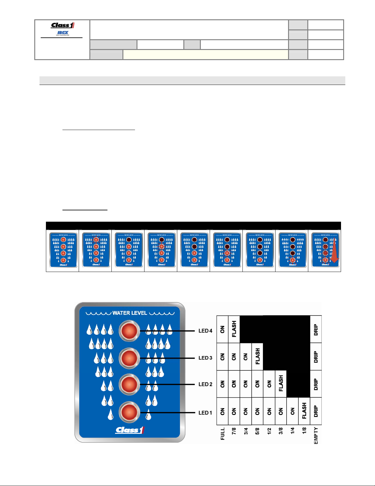
3.1.2. Level indications
FULL 7/8 3/4 5/8 1/2 3/8 1/4 1/8 EMPTY
SUITABLE FOR EXTERNAL DISTRIBUTION
OPERATION MANUAL
4 LIGHT INTELLI-TANK DISPLAY WITH 1-wire and CAN
PAGE
DATE 10/23/2007
BY AMS
3 of 22
DRIP = cascades from top (LED 4) to bottom (LED 1), pauses, and repeats.
DATASHEET P/N:114356 - UNCONTROLLED IN PRINTED FORMAT - PRINTED: 10/24/07
Page 5
FORM-ENG-0018 REV A 05-27-03
607 NW 27th Ave
Ocala, FL 34475
Ph: 352-629-5020 or 1-800-533-3569
Fax : 352-629-2902 or 1-800-520-3473
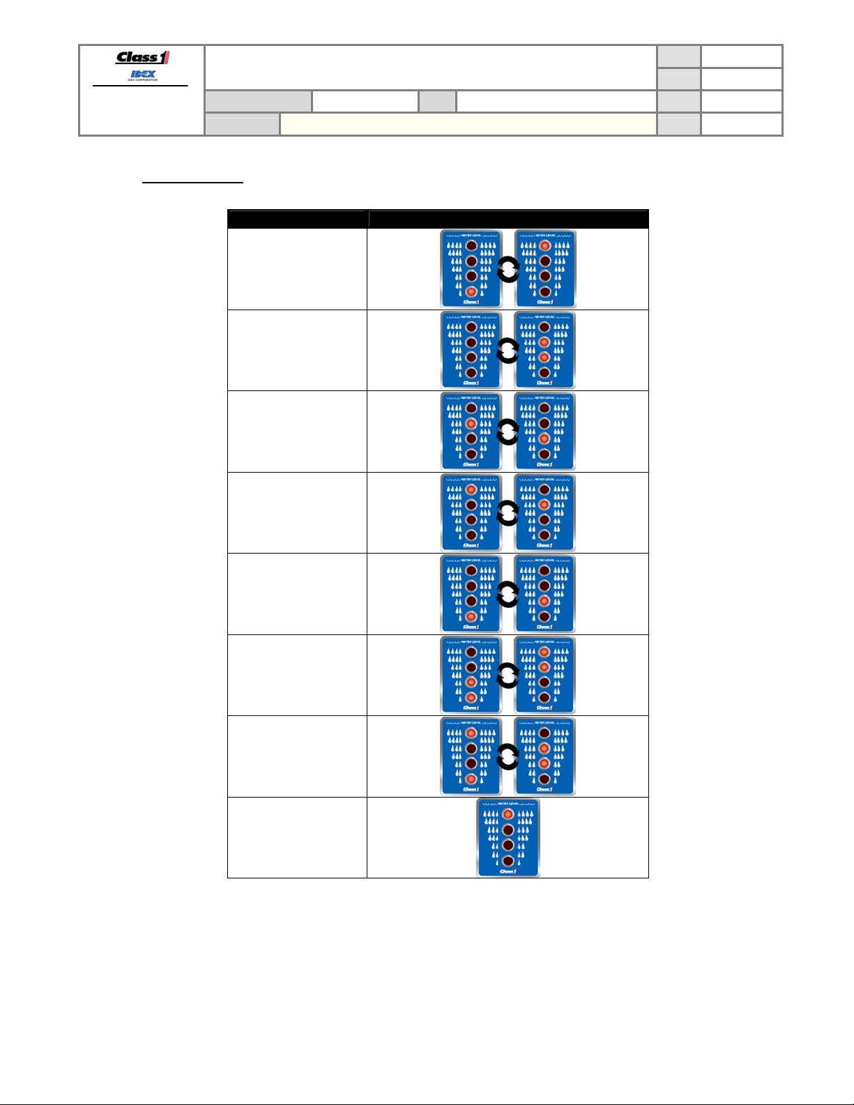
3.1.3. Error indications
SUITABLE FOR EXTERNAL DISTRIBUTION
OPERATION MANUAL
PRODUCT GROUP ITL P/N 12V: 113739 ; 24V: 114378 REV 1.20
PRODUCT
4 LIGHT INTELLI-TANK DISPLAY WITH 1-wire and CAN
PAGE
DATE 10/23/2007
BY AMS
4 of 22
Condition Visual
Invalid calibration
Incomplete calibration
EEPROM error
Transducer signal
voltage above 4.8V
Transducer signal
voltage below .4V
Remote “NO DATA”
Password Error
“wave off”
Unit type error
(1)
(2)
DATASHEET P/N:114356 - UNCONTROLLED IN PRINTED FORMAT - PRINTED: 10/24/07
(1)”
Wave off” pattern: two center LEDs and then two outer LEDs flashing quickly for 8 cycles.
(2)
Indicates that the unit type has erroneously changed. The two valid unit types are Remote and Master.
Page 6
FORM-ENG-0018 REV A 05-27-03
607 NW 27th Ave
Ocala, FL 34475
Ph: 352-629-5020 or 1-800-533-3569
Fax : 352-629-2902 or 1-800-520-3473
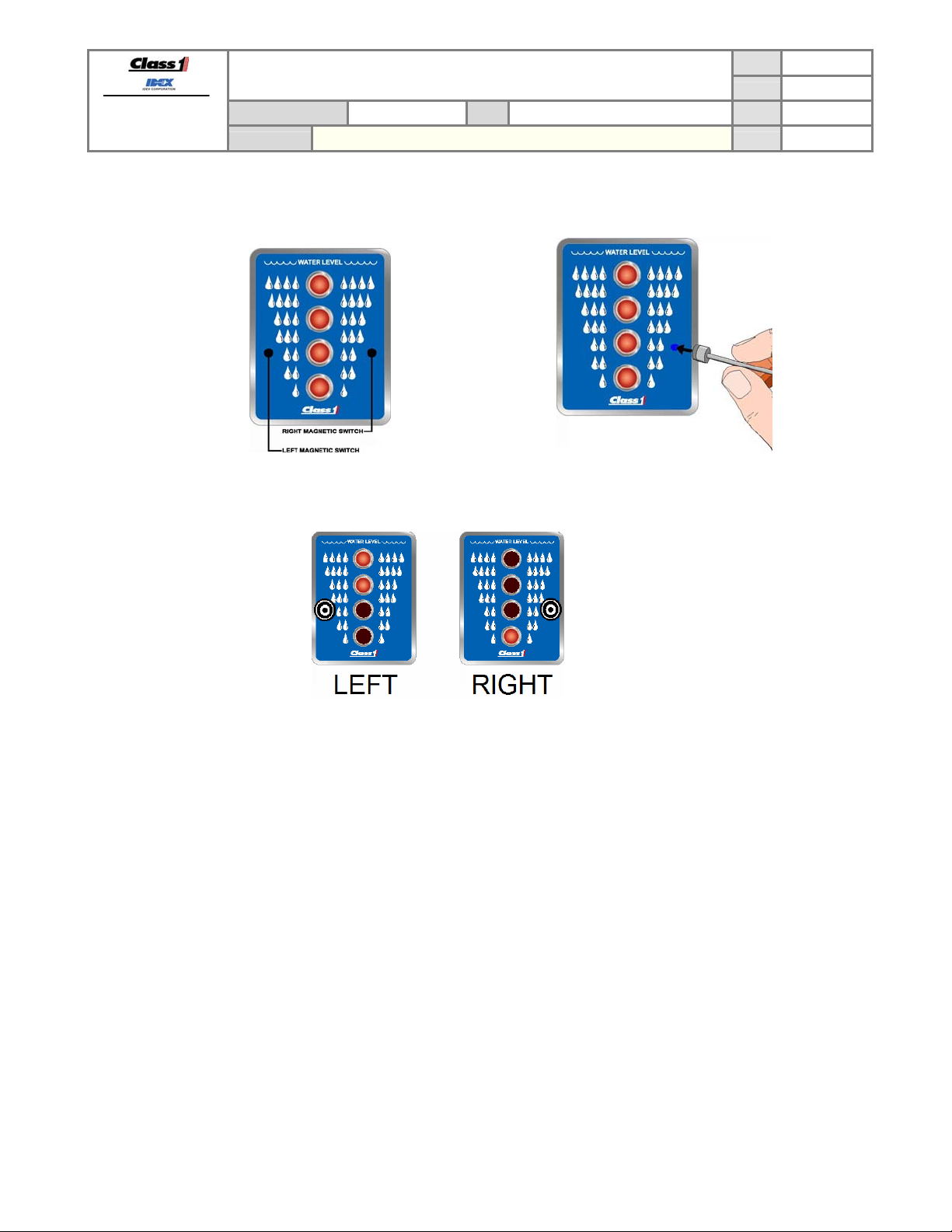
3.2. Magnetic switches
The display has two magnetic switches (left and right). The magnetic switches are activated by using a magnet and
touching the front of the display on either side of LED 2.
For best results the magnet should be positioned over the desired magnet approximately 2 inches from the front of
the display, pushed directly to the front of the display, and then pulled back to the start position.
PRODUCT GROUP ITL P/N 12V: 113739 ; 24V: 114378 REV 1.20
PRODUCT
SUITABLE FOR EXTERNAL DISTRIBUTION
OPERATION MANUAL
4 LIGHT INTELLI-TANK DISPLAY WITH 1-wire and CAN
PAGE
DATE 10/23/2007
BY AMS
5 of 22
The LEDs on the display will indicate which switch was activated (upper two LEDs = left switch, bottom LED = right
switch) for approximately half a second and then the display will go blank.
The maximum time between magnetic switch activations is two seconds. If longer than two seconds have passed
between activations the unit will resume normal operation and the password attempted will be reset.
DATASHEET P/N:114356 - UNCONTROLLED IN PRINTED FORMAT - PRINTED: 10/24/07
Page 7
FORM-ENG-0018 REV A 05-27-03
607 NW 27th Ave
Ocala, FL 34475
Ph: 352-629-5020 or 1-800-533-3569
Fax : 352-629-2902 or 1-800-520-3473
3.3. Calibration
The ITL display can be calibrated four different ways: 1-point (quick calibration), 2-point (level calibration), 5-point and
9-point (volume calibration).
To enter calibration mode use a magnet and activate the magnetic switches in the order of the appropriate password.
SUITABLE FOR EXTERNAL DISTRIBUTION
OPERATION MANUAL
PRODUCT GROUP ITL P/N 12V: 113739 ; 24V: 114378 REV 1.20
PRODUCT
4 LIGHT INTELLI-TANK DISPLAY WITH 1-wire and CAN
PAGE
DATE 10/23/2007
BY AMS
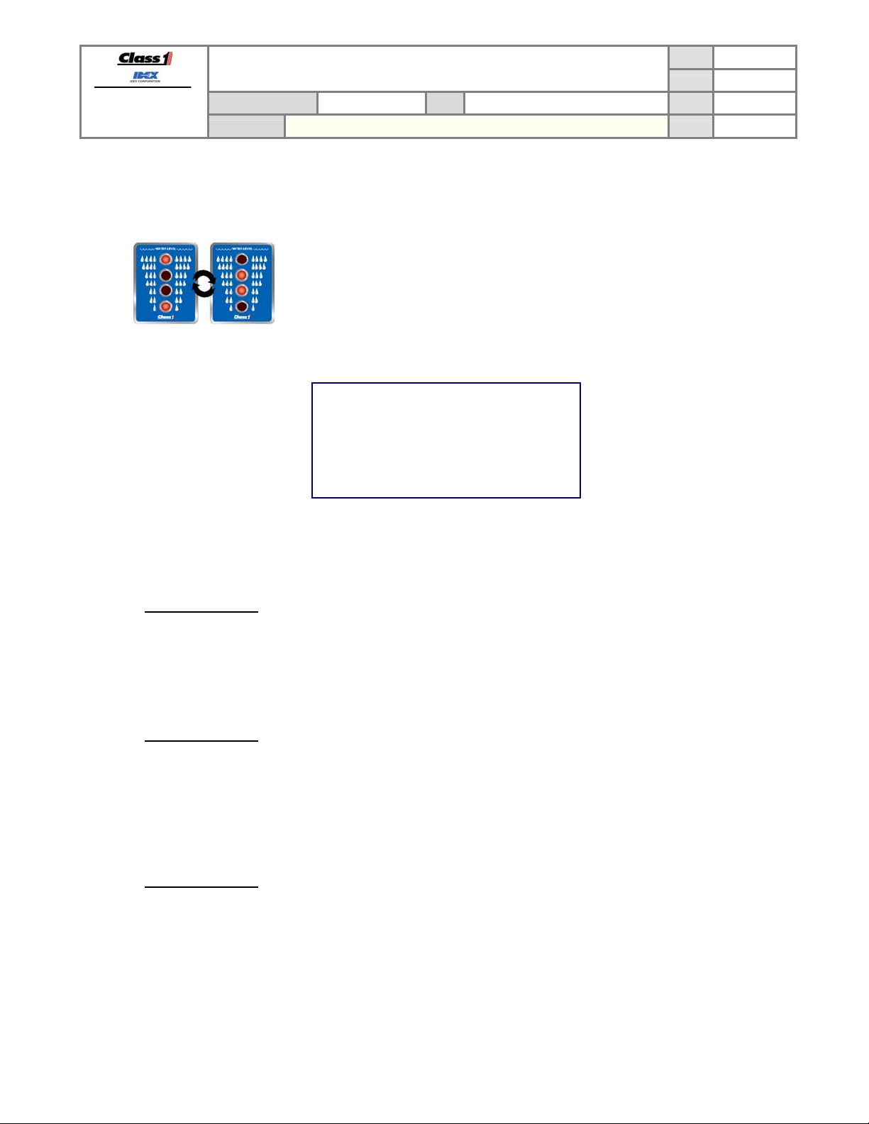
Entering an invalid password will initiate a “wave off” pattern on the display. (Two
center LEDs, two outer LEDs flashing quickly for 8 cycles.) The unit will then
resume its normal operation and the user can attempt to re-enter the password.
Calibrate the unit by entering the desired point calibration password –
1 point RLLR LRRL
(see section 3.3.1)
6 of 22
2 point RLLR LLRL
5 point RLLR LRLR
9 point RLLR RLLR
(see section 3.3.2)
(see section 3.3.3)
(see section 3.3.4)
During calibration, the process can be cancelled at any time by activating the LEFT magnetic switch. This will
allow the display to exit without showing an “incomplete calibration error” (section 3.1.3) on the next power
cycle.
3.3.1. 1 Point Calibration
1 point calibration only calibrates the full point. The empty calibration is always set to 0.55V (approximately 1.5
inches of liquid).
1. Make certain that the tank is FULL.
2. Enter the password RLLR LRRL. The display will respond by flashing the top LED twice. The display will
then revert to normal operation by displaying FULL (all LEDs on).
3.3.2. 2 Point Calibration
1. Enter the password RLLR LLRL. The display will respond by flashing the two center LEDs twice. The
display will then begin cascading the LEDs from top to bottom (drip).
2. Make certain that the tank is EMPTY and then activate the RIGHT switch to store that point. The display will
flash the top LED and then turn on all four LEDs.
3. Fill the tank and then activate the RIGHT switch. The display will respond by flashing the top LED then
lighting the two center LEDs and then reverting to normal operation by displaying FULL (all LEDs on).
3.3.3. 5 Point Calibration
1. Enter the password RLLR LRLR. The display will respond by flashing the two center LEDs five times. The
display will then begin cascading the LEDs from top to bottom (drip).
2. Make certain that the tank is EMPTY and then activate the RIGHT switch to store that point. The display will
flash the top LED and then turn on the bottom LED.
3. Fill the tank to the one-quarter tank point and then activate the RIGHT switch. The display will flash the top
LED and then turn on the bottom two LEDs.
4. Fill the tank to the one-half tank point and then activate the RIGHT switch. The display will flash the top LED
and then turn on the bottom three LEDs.
DATASHEET P/N:114356 - UNCONTROLLED IN PRINTED FORMAT - PRINTED: 10/24/07
Page 8

FORM-ENG-0018 REV A 05-27-03
607 NW 27th Ave
Ocala, FL 34475
Ph: 352-629-5020 or 1-800-533-3569
Fax : 352-629-2902 or 1-800-520-3473
SUITABLE FOR EXTERNAL DISTRIBUTION
OPERATION MANUAL
PRODUCT GROUP ITL P/N 12V: 113739 ; 24V: 114378 REV 1.20
PRODUCT
4 LIGHT INTELLI-TANK DISPLAY WITH 1-wire and CAN
PAGE
DATE 10/23/2007
BY AMS
7 of 22
5. Fill the tank to the three-quarter tank point and then activate the RIGHT switch. The display will flash the top
LED and then turn on all four LEDs.
6. Fill the tank to the full point and then activate the RIGHT switch. The display will respond by flashing the top
LED then lighting the two center LEDs and then reverting to normal operation by displaying FULL (all LEDs
on).
3.3.4. 9 Point Calibration
1. Enter the password RLLR RLLR. The display will respond by flashing the two center LEDs nine times. The
display will then begin cascading the LEDs from top to bottom (drip).
2. Make certain that the tank is EMPTY and then activate the RIGHT switch to store that point. The display will
flash the top LED and then begin flashing the bottom LED.
3. Fill the tank to the one-eighth point and then activate the RIGHT switch. The display will flash the top LED
and then turn on the bottom LED.
4. Fill the tank to the one-quarter tank point and then activate the RIGHT switch. The display will flash the top
LED and then turn on the bottom LED and flash the second LED.
5. Fill the tank to the three-eighths point and then activate the RIGHT switch. The display will flash the top LED
and then turn on the bottom two LEDs.
6. Fill the tank to the one-half point and then activate the RIGHT switch. The display will flash the top LED and
then turn on the bottom two LEDs and flash the third LED.
7. Fill the tank to the five-eighths point and then activate the RIGHT switch. The display will flash the top LED
and then turn on the bottom three LEDs.
8. Fill the tank to the three-quarter point and then activate the RIGHT switch. The display will flash the top LED
and then turn on the bottom three LEDs and flash the fourth LED.
9. Fill the tank to the seven-eighths point and then activate the RIGHT switch. The display will flash the top
LED and then turn on all four LEDs.
10. Fill the tank to the full point and then activate the RIGHT switch. The display will respond by flashing the top
LED then lighting the two center LEDs and then reverting to normal operation by displaying FULL (all LEDs
on).
3.3.5. Calibration retention
Calibration data is saved in non-volatile memory (EEPROM) and the display does not need power to retain
calibration data.
3.3.6. Invalid calibration
Calibration automatically makes the display a master if the calibration is valid. An invalid calibration is determined
when any calibrated point is not at a higher level than the previous calibrated point, or if the transducer voltage falls
outside of the valid minimum (.4V) or maximum (4.8V) range. An invalid calibration is acknowledged by giving the
“wave off” and if this was a master display previously will show an “invalid calibration error” (section 3.1.3), while a
Remote will revert to Remote operation.
3.3.7. Calibration incomplete
If the calibration is not completed the display will continually flash the “incomplete calibration error” (section 3.1.3),
during all subsequent power cycles. This indicates that a calibration was attempted but never completed.
Recalibrate the display completely to remove this error condition.
3.4. Self test
The Tank Level can check its hardware for proper operation by entering the password RLLR LLRR.
The display will then cycle each LED ON individually starting with the bottom LED and then all LEDs will come on and
begin flashing between full bright and the calibrated dim level for 5 seconds. The display will then show the condition
of the self test for 5 seconds.
DATASHEET P/N:114356 - UNCONTROLLED IN PRINTED FORMAT - PRINTED: 10/24/07
Page 9

FORM-ENG-0018 REV A 05-27-03
607 NW 27th Ave
Ocala, FL 34475
Ph: 352-629-5020 or 1-800-533-3569
Fax : 352-629-2902 or 1-800-520-3473
PRODUCT GROUP ITL P/N 12V: 113739 ; 24V: 114378 REV 1.20
PRODUCT
SUITABLE FOR EXTERNAL DISTRIBUTION
OPERATION MANUAL
4 LIGHT INTELLI-TANK DISPLAY WITH 1-wire and CAN
A PASS condition is indicated when only the top LED (LED 4) is on.
A FAIL condition exists if LED 4 is off and any other LED is on.
LED 3 ON Memory (EEPROM) failure.
LED 2 ON Data communication error.
LED 1 ON Transducer signal line out of tolerance high (above 4.8V) or shorted to +5V.
LED 1 Flashing Transducer signal out of tolerance low (below 0.4V) or shorted to ground.
If the self test password is used on a Master display all Remote displays will also perform their self test.
3.5. Setting the dim LED level
The display can be dimmed by applying system power to pin 3 (Dim Display input). To select the dim level of the
display use the magnetic switches to enter the password RLLR LLLR.
All of the LEDs will be illuminated during the set-up. Hold the magnet against the RIGHT switch and the display will
either brighten or dim. Release the magnet and again hold it against the RIGHT switch and the display’s brightness
will move in the opposite direction. When the dim level is at the desired point activate the LEFT switch.
3.6. Show display type and address indications (CAN communication)
Hold a magnet to the right magnetic switch during power up and the LED states will verify the display type, display
address, and communication method.
LED 4 shows the communication method, LED3 shows the display type, and LEDs 2 and 1 show the CAN
communication address.
PAGE
DATE 10/23/2007
BY AMS
8 of 22
3.7. Configuring the communication method
A Master display can communicate to other displays that are configured as remotes via CAN or 1-wire.
The 1-wire communication method was used on the original ITL displays. Use this method if older ITL displays will be
utilized along with the new display. This method also only uses 1 communication wire (make certain that all displays
on the 1-wire communication line have the exact same ground potential).
DATASHEET P/N:114356 - UNCONTROLLED IN PRINTED FORMAT - PRINTED: 10/24/07
Page 10

FORM-ENG-0018 REV A 05-27-03
607 NW 27th Ave
Ocala, FL 34475
Ph: 352-629-5020 or 1-800-533-3569
Fax : 352-629-2902 or 1-800-520-3473
PRODUCT GROUP ITL P/N 12V: 113739 ; 24V: 114378 REV 1.20
PRODUCT
SUITABLE FOR EXTERNAL DISTRIBUTION
OPERATION MANUAL
4 LIGHT INTELLI-TANK DISPLAY WITH 1-wire and CAN
The CAN communication method is new for the ITL displays and is a more robust communication method. This
method requires two wires (CAN high, CAN low) and approved J1939 CAN wiring and connectors. There should be
two 120 ohm terminating resistors located at the ends of the CAN bus.
3.7.1. Configuring a display as a Master with 1-wire communications
Enter the password LRLL LLLR to set the communication method to 1-wire. If the display was not previously a
Master display, calibrate the display
(see section 3.3).
3.7.2. Configuring a display as a Remote with 1-wire communications
Enter the password LRLL LLLR to set the communication method to 1-wire. If the display is a Master display,
enter the password LRLR LRLR to turn the display into a Remote.
3.7.3. Configuring a display as a Master with CAN communications
Enter the password LRLL LLRL to set the communication method to CAN. If the display was not previously a
Master display, calibrate the display
(see section 3.3).
Choose the CAN identification address to use (either address 1, 2, or 3) and enter the appropriate password to set
the address (LRRR LLLL address 1, LRRR LLLR address 2, LRRR LRRR address 3). All Remote displays that
are to mimic this Master display must have their addresses matching the Master’s.
3.7.4. Configuring a display as a Remote with CAN communications
Choose the CAN identification address to use (either address 1, 2, or 3) and enter the appropriate password to set
the address (LRRR LLRL address 1, LRRR LLRR address 2, LRRR LRRL address 3). All Remote displays that
are to mimic the Master display must have their addresses matching the Master’s.
The display can also be configured to mimic a Class 1 Pump Sensor Module by entering the password (LRRR
LRLL).
PAGE
DATE 10/23/2007
BY AMS
9 of 22
DATASHEET P/N:114356 - UNCONTROLLED IN PRINTED FORMAT - PRINTED: 10/24/07
Page 11

FORM-ENG-0018 REV A 05-27-03
607 NW 27th Ave
Ocala, FL 34475
Ph: 352-629-5020 or 1-800-533-3569
Fax : 352-629-2902 or 1-800-520-3473
4. Password list
RLLR LRRL
SUITABLE FOR EXTERNAL DISTRIBUTION
OPERATION MANUAL
PRODUCT GROUP ITL P/N 12V: 113739 ; 24V: 114378 REV 1.20
PRODUCT
4 LIGHT INTELLI-TANK DISPLAY WITH 1-wire and CAN
PAGE
DATE 10/23/2007
BY AMS
10 of 22
1 point calibration (section 3.3.1)
RLLR LLRL
2 point calibration (section 3.3.2)
RLLR LRLR 5 point calibration (section 3.3.3)
RLLR RLLR 9 point calibration (section 3.3.4)
RLLR LLRR Self test (section 3.4)
LRLR LRLR Configure display as Remote display (section 2.2)
RLLR LLLR Configure dim level (section 3.5)
LLRR LLRR Display voltage (section 8.2)
LRLL LLLR Configure for 1-wire communications (section 3.7)
LRLL LLRL Configure for CAN communications (section 3.7)
LRRR LLLL Configure as Master display with CAN address 1 (section 3.7.3)
LRRR LLLR Configure as Master display with CAN address 2 (section 3.7.3)
LRRR LRRR Configure as Master display with CAN address 3 (section 3.7.3)
LRRR LLRL Configure as Remote display with CAN address 1 (section 3.7.4)
LRRR LLRR Configure as Remote display with CAN address 2 (section 3.7.4)
LRRR LRRL Configure as Remote display with CAN address 3 (section 3.7.4)
Configure as Remote display for use with Pump Sensor Module
LRRR LRLL
(Tank 1)
Configure as Remote display for use with Pump Sensor Module
LRRR RLRL
(Tank 2)
Configure as Remote display for use with Pump Sensor Module
LRRR RLRR
DATASHEET P/N:114356 - UNCONTROLLED IN PRINTED FORMAT - PRINTED: 10/24/07
(Tank 3)
Page 12

FORM-ENG-0018 REV A 05-27-03
607 NW 27th Ave
Ocala, FL 34475
Ph: 352-629-5020 or 1-800-533-3569
Fax : 352-629-2902 or 1-800-520-3473
PRODUCT GROUP ITL P/N 12V: 113739 ; 24V: 114378 REV 1.20
PRODUCT
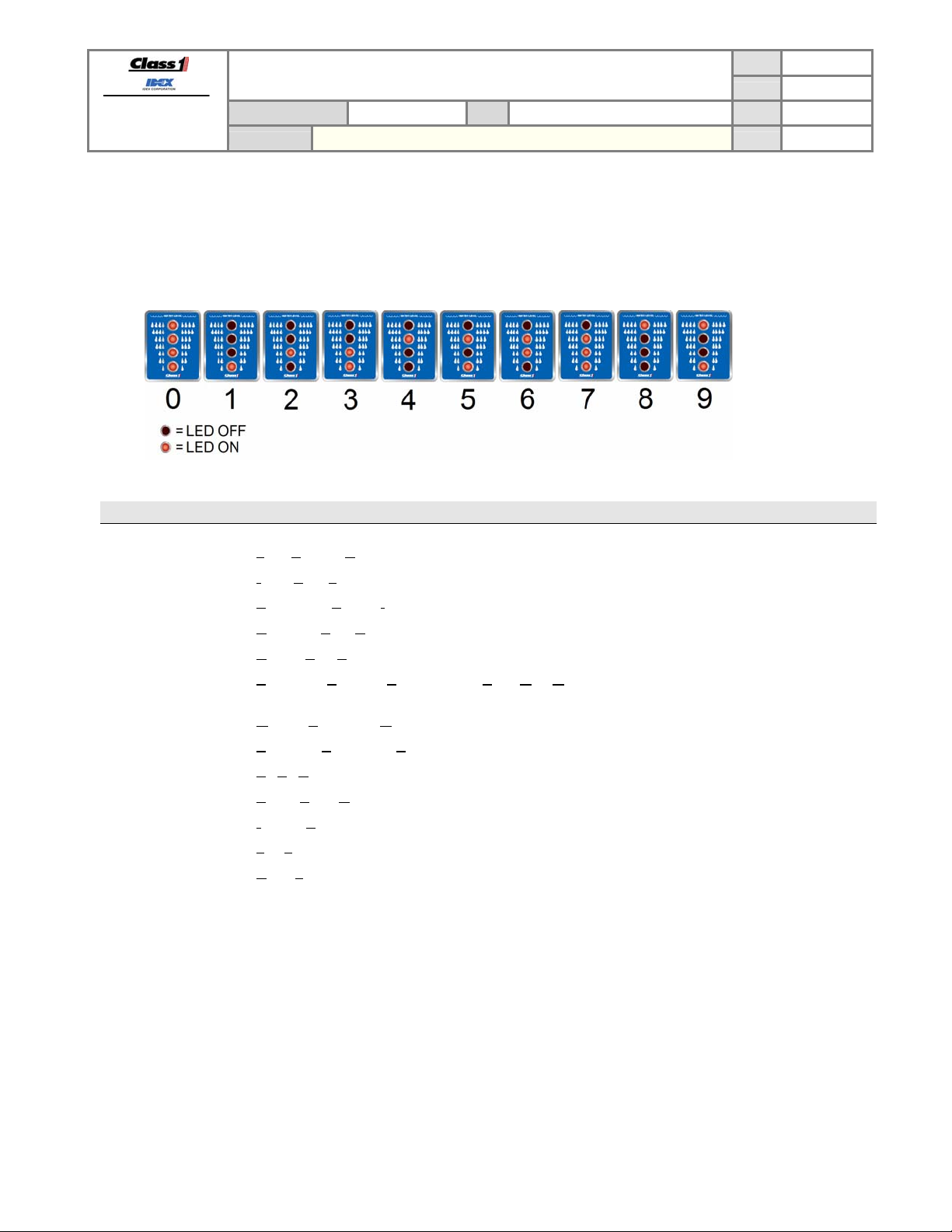
5. Software revision check
Hold a magnet on the LEFT magnetic switch while powering the display. The LEDs will display the software revision.
(Use the chart below to decipher).
SUITABLE FOR EXTERNAL DISTRIBUTION
OPERATION MANUAL
4 LIGHT INTELLI-TANK DISPLAY WITH 1-wire and CAN
PAGE
DATE 10/23/2007
BY AMS
11 of 22
Example. (LED 4 – OFF, LED 3 – ON, LED 2 – OFF, LED 1 – ON) = Ver 1.1
DATASHEET P/N:114356 - UNCONTROLLED IN PRINTED FORMAT - PRINTED: 10/24/07
Page 13

FORM-ENG-0018 REV A 05-27-03
607 NW 27th Ave
Ocala, FL 34475
Ph: 352-629-5020 or 1-800-533-3569
Fax : 352-629-2902 or 1-800-520-3473
PRODUCT GROUP ITL P/N 12V: 113739 ; 24V: 114378 REV 1.20
PRODUCT
6. Installation
6.1. Cutout dimensions
The display requires a cutout as shown. The display is water tight and may be mounted in any location on the
operator’s panel.
SUITABLE FOR EXTERNAL DISTRIBUTION
OPERATION MANUAL
4 LIGHT INTELLI-TANK DISPLAY WITH 1-wire and CAN
PAGE
DATE 10/23/2007
BY AMS
12 of 22
Unit of scale: inches [millimeters]
6.2. Outer bezel dimensions
Unit of scale: inches [millimeters]
DATASHEET P/N:114356 - UNCONTROLLED IN PRINTED FORMAT - PRINTED: 10/24/07
Page 14
FORM-ENG-0018 REV A 05-27-03
607 NW 27th Ave
Ocala, FL 34475
Ph: 352-629-5020 or 1-800-533-3569
Fax : 352-629-2902 or 1-800-520-3473
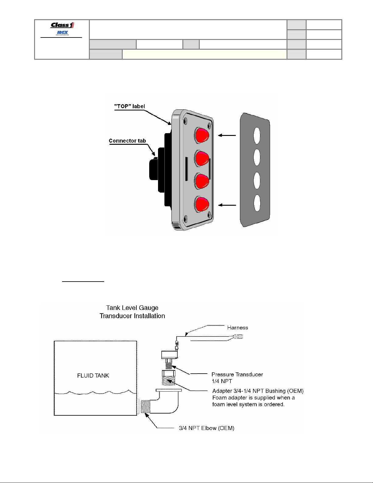
6.3. Label orientation
Before mounting the display and adhering the label insure that the display is situated correctly (TOP is UP). Refer to
the drawing for orientation.
PRODUCT GROUP ITL P/N 12V: 113739 ; 24V: 114378 REV 1.20
PRODUCT
SUITABLE FOR EXTERNAL DISTRIBUTION
OPERATION MANUAL
4 LIGHT INTELLI-TANK DISPLAY WITH 1-wire and CAN
PAGE
DATE 10/23/2007
BY AMS
13 of 22
6.4. Pressure transducer
The transducer has a ¼” NPT mount and must be mounted vertically as depicted to insure an accurate reading.
6.4.1. Approved fluids
The pressure transducer has been tested and approved for water, foam A, and foam B.
DATASHEET P/N:114356 - UNCONTROLLED IN PRINTED FORMAT - PRINTED: 10/24/07
Page 15

FORM-ENG-0018 REV A 05-27-03
607 NW 27th Ave
Ocala, FL 34475
Ph: 352-629-5020 or 1-800-533-3569
Fax : 352-629-2902 or 1-800-520-3473
PRODUCT GROUP ITL P/N 12V: 113739 ; 24V: 114378 REV 1.20
PRODUCT
7. Wiring
7.1. Power and Ground
It is imperative that a system utilizing Master and Remote tank level displays connected by the 1-wire data line have a
common ground. The remote displays will not follow the master display otherwise.
Pin 1 System voltage
Pin 2 Ground
7.2. Dim Function
The LEDs on the tank level display can be dimmed to a user selectable dim setting by applying system voltage to the
Dim display Input.
Pin 3 Dim display input (system voltage)
7.3. Transducer Connection
Pin 6 Sensor power (+5)
Pin 7 Sensor signal
Pin 8 Sensor ground
SUITABLE FOR EXTERNAL DISTRIBUTION
OPERATION MANUAL
4 LIGHT INTELLI-TANK DISPLAY WITH 1-wire and CAN
PAGE
DATE 10/23/2007
BY AMS
14 of 22
7.4. Communication Data Line(s)
Pin 4 CAN high communication line (or 1-wire communication line)
Pin 5 CAN low communication line
DATASHEET P/N:114356 - UNCONTROLLED IN PRINTED FORMAT - PRINTED: 10/24/07
Page 16

FORM-ENG-0018 REV A 05-27-03
607 NW 27th Ave
Ocala, FL 34475
Ph: 352-629-5020 or 1-800-533-3569
Fax : 352-629-2902 or 1-800-520-3473
PRODUCT GROUP ITL P/N 12V: 113739 ; 24V: 114378 REV 1.20
PRODUCT
SUITABLE FOR EXTERNAL DISTRIBUTION
OPERATION MANUAL
4 LIGHT INTELLI-TANK DISPLAY WITH 1-wire and CAN
7.5. Communication wiring examples
The displays can be set up to use the 1-wire or CAN communication methods. A standard system could be
comprised of as few as 1 master display. Two master displays may be used in a system where two fluid levels must
be displayed (for example, 1 water tank and 1 foam tank).
7.5.1. 1-wire method, 1 master and 3 remotes
PAGE
DATE 10/23/2007
BY AMS
15 of 22
System configured with 1-wire communication method. Make certain that the ground for each display is tied to a
common point or the remote displays will not follow the master display.
7.5.2. 1-wire method, 2 masters and 2 remotes
System configured with 1-wire communication method. Make certain that the two master 1-wire data lines are not
connected and that the ground for each display is tied to a common point or the remote displays will not follow the
master displays.
DATASHEET P/N:114356 - UNCONTROLLED IN PRINTED FORMAT - PRINTED: 10/24/07
Page 17
FORM-ENG-0018 REV A 05-27-03
607 NW 27th Ave
Ocala, FL 34475
Ph: 352-629-5020 or 1-800-533-3569
Fax : 352-629-2902 or 1-800-520-3473
PRODUCT GROUP ITL P/N 12V: 113739 ; 24V: 114378 REV 1.20
PRODUCT
SUITABLE FOR EXTERNAL DISTRIBUTION
OPERATION MANUAL
4 LIGHT INTELLI-TANK DISPLAY WITH 1-wire and CAN
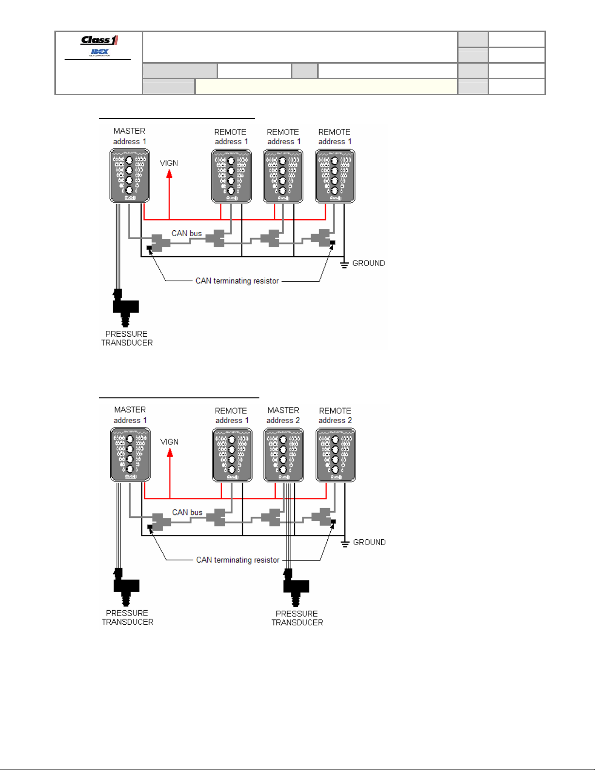
7.5.3. CAN method, 1 master and 3 remotes
PAGE
DATE 10/23/2007
BY AMS
16 of 22
System configured with CAN communication method. This example shows one master display (address 1)
communicating with 3 remote displays (address 1).
7.5.4. CAN method, 2 masters and 2 remotes
System configured with CAN communication method. This example shows two master displays (address 1 and 2)
communicating with 2 remote displays (address 1 and 2). Remote display address 1 only follows the indications of
master display address 1, and remote display address 2 only follows the indications of master display address 2.
DATASHEET P/N:114356 - UNCONTROLLED IN PRINTED FORMAT - PRINTED: 10/24/07
Page 18
FORM-ENG-0018 REV A 05-27-03
607 NW 27th Ave
Ocala, FL 34475
Ph: 352-629-5020 or 1-800-533-3569
Fax : 352-629-2902 or 1-800-520-3473
PRODUCT GROUP ITL P/N 12V: 113739 ; 24V: 114378 REV 1.20
PRODUCT
SUITABLE FOR EXTERNAL DISTRIBUTION
OPERATION MANUAL
4 LIGHT INTELLI-TANK DISPLAY WITH 1-wire and CAN
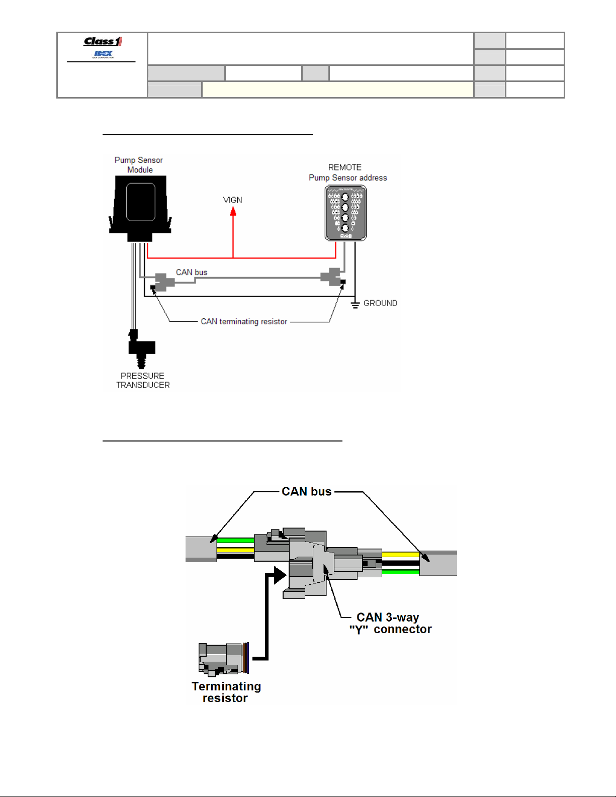
7.5.5. CAN method, pump sensor module and 1 remote
PAGE
DATE 10/23/2007
BY AMS
17 of 22
System configured with CAN communication method. This example shows one remote display (using pump
sensor module address) following the indications of the Class 1 Pump Sensor Module.
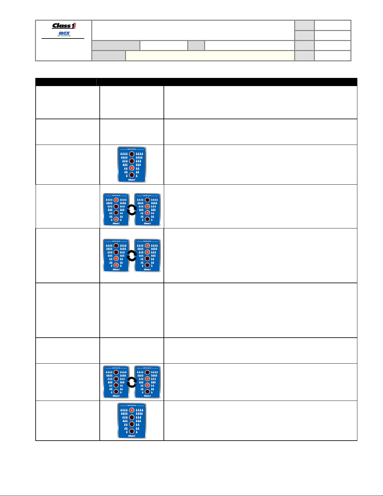
7.5.6. Terminating resistor requirement (CAN communication)
A terminating resistor (120 Ohm) is required on both ends of the CAN bus for proper operation. Only two
terminating resistors are allowed on a CAN bus.
Terminating resistor p/n DT06-3S-P006
CAN “Y” connector p/n DT04-3P-P007
DATASHEET P/N:114356 - UNCONTROLLED IN PRINTED FORMAT - PRINTED: 10/24/07
Page 19

FORM-ENG-0018 REV A 05-27-03
607 NW 27th Ave
Ocala, FL 34475
Ph: 352-629-5020 or 1-800-533-3569
Fax : 352-629-2902 or 1-800-520-3473
PRODUCT GROUP ITL P/N 12V: 113739 ; 24V: 114378 REV 1.20
PRODUCT
7.6. System compatibility
The ITL display is compatible with other Class 1 CAN and 1-wire products.
7.6.1. 1-wire compatibility
An ITL display configured with 1-wire communication is compatible with the 4 light remote driver module (p/n
106877), Pump input sensor module (p/n 111097), mini remote driver module (p/n 112648), mini remote dash
gauge (p/n 112649), and all older 4 and 5 light ITL displays (p/n 106299, 106296, 108858, 108859).
7.6.2. CAN compatibility
The ITL display configured with CAN communications is compatible with the Command Master (p/n 111084,
111085, 111086), Pump input sensor module (p/n 111097), and future Class 1 ES-Key CAN products.
8. Troubleshooting
8.1. Evaluation table
Condition Visual Evaluate
Bottom two LEDs
alternate flashing.
Unit fails self test, LED 1
flashing.
Top two LEDs alternate
flashing.
Unit fails self test, LED 1
on.
SUITABLE FOR EXTERNAL DISTRIBUTION
OPERATION MANUAL
4 LIGHT INTELLI-TANK DISPLAY WITH 1-wire and CAN
Check transducer wiring. Ensure +5V at pin A, ground at pin B and at least .4V at
pin C (Signal).
Check transducer wiring. Ensure +5V at pin A, ground at pin B and no more than
4.8V at pin C (Signal).
PAGE
DATE 10/23/2007
BY AMS
18 of 22
Middle two LEDs
alternate flashing.
Perform self test. If it fails with LED 3 on replace display.
Try to recalibrate. If condition remains, check if transducer signal voltage (pin C)
Outer two LEDs
alternate flashing.
changes as tank level increases. If it doesn’t, replace transducer. If it does, verify
depth of tank. It may be impossible to calibrate a tank with a depth of less than 6
inches.
Bottom two and Upper
two LEDs alternate
flashing.
The display is configured as a Remote. Recalibrate if a Master is required. If the
display is required to be a Remote check Data line(s) (Pin 4, 5) continuity and
insure line(s) is(are) not grounded.
No LEDS on.
Check power (Pin 1) and ground (Pin 2) connection.
DATASHEET P/N:114356 - UNCONTROLLED IN PRINTED FORMAT - PRINTED: 10/24/07
Page 20
FORM-ENG-0018 REV A 05-27-03
607 NW 27th Ave
Ocala, FL 34475
Ph: 352-629-5020 or 1-800-533-3569
Fax : 352-629-2902 or 1-800-520-3473
Condition Visual Evaluate
Master Tank level unit
does not change when
actual tank level is
changing.
SUITABLE FOR EXTERNAL DISTRIBUTION
OPERATION MANUAL
PRODUCT GROUP ITL P/N 12V: 113739 ; 24V: 114378 REV 1.20
PRODUCT
4 LIGHT INTELLI-TANK DISPLAY WITH 1-wire and CAN
PAGE
DATE 10/23/2007
BY AMS
19 of 22
Check transducer wiring. Ensure transducer signal voltage (Pin C) is varying. If it
No picture
does, check for same signal changes at Pin 6 of tank level connector (if it is not
the same repair wiring). If signal is good at both locations try re-calibrating.
Remote Tank level unit
does not follow Master
display.
Unit fails self test, LED 2
on.
No passwords are
accepted.
The bottom two LEDs
are on and occasionally
they go out and the top
two flash and then return
to the bottom two LEDs
on (or vice-versa).
(REMOTE).
The points calibrated
seemed to have
changed.
No picture
No picture
Perform self test. If self test is good, check pin 4 (data line) for continuity and
insure it is not shorted to ground or power. Insure data line is not routed near
noisy power or RF sources.
Check pin 4 (data line) for continuity and insure it is not shorted to ground or
power.
If the display issues the “wave off” after entering a password, insure the display is
installed upright. During power-up the display should cycle on each LED
individually starting with the bottom LED.
Check that the left and right magnetic switches are recognized by activating each
switch and verifying that the associated LEDs illuminate.
Check for large noise spikes on the 1-wire data line.
Insure that the display’s ground potential is the same as the Master’s.
Insure that the data line is not chaffed and making contact with other electrical
wires.
Self test the display to check for any malfunctions.
Check the pressure transducer for problems.
Recalibrate the display and take a voltage reading from the transducer (pin 7 on
the display’s connector) at each calibration point. When the calibration points
again look wrong check the voltages at those points and determine if they are the
same as the voltage reading taken during calibration.
Insure the Dim input voltage on Pin 3 is at least 9V. Recalibrate dim setting
Unit will not dim display.
No picture
(RLLR LLLR). If display does not dim LEDs while in dim calibrate mode, replace
display.
The middle two LEDs
are flashing together.
A calibration was started on the display but not completed correctly. Set the
display to a REMOTE display (LRLR LRLR) or calibrate it as a MASTER (follow
calibration steps exactly).
Top LED is the only LED
illuminated.
The display has had a unit type memory error.
Attempt to set the display back to REMOTE or MASTER as required.
DATASHEET P/N:114356 - UNCONTROLLED IN PRINTED FORMAT - PRINTED: 10/24/07
Page 21
FORM-ENG-0018 REV A 05-27-03
607 NW 27th Ave
Ocala, FL 34475
Ph: 352-629-5020 or 1-800-533-3569
Fax : 352-629-2902 or 1-800-520-3473
SUITABLE FOR EXTERNAL DISTRIBUTION
OPERATION MANUAL
PRODUCT GROUP ITL P/N 12V: 113739 ; 24V: 114378 REV 1.20
PRODUCT
4 LIGHT INTELLI-TANK DISPLAY WITH 1-wire and CAN
PAGE
DATE 10/23/2007
BY AMS
8.2. Using the display to verify voltage
The display can show the voltage level that it detects on the transducer signal line by entering the password LLRR
LLRR.
The display will then cycle through three LED patterns, pause, and then repeat. The three patterns each equate to a
digit of the detected voltage. For example, if the three patterns shown were 1, 4, and 7, the voltage would be 1.47
volts.
The display will continue showing the voltage until either of the magnetic switches is activated.
9. Glossary
LED Light Emitting Diode. The lights on the display used to show tank level and information.
ITL I
PSI P
CAN Controller Area Network. SAE J1939 communication method.
NPT N
EEPROM Electrically Erasable Programmable Read-Only Memory. The memory of the tank level display,
OEM O
SAE S
TBD T
ESD E
IP I
p/n p
C1 C
Master Master display. The tank level display wired to the transducer. This display transmits data to other
Remote Remote display. A tank level display that receives data from the master unit. The remote display
1-wire Proprietary communication method that uses only one wire for data transfer.
System voltage The normal power level used by the system or vehicle. This voltage level will normally come from
Sensor The pressure transducer.
Foam A Class “A” type foam used when fighting fires where the cooling effect of water is of prime
Foam B Class “B” type foam used when fighting fires involving flammable liquids where blanketing or
ntelli-Tank Level. The tank level display.
ounds per Square Inch. Pressure measurement.
ormal Pipe Taper. Pipe thread specification.
used to store the display information (tank level points, display type, dim value, etc).
riginal Equipment Manufacturer.
ociety of Automotive Engineers.
o Be Developed.
lectroStatic Discharge.
ngress Protection (IP 67, etc).
art number
lass 1
remote displays.
will only display what the master display commands.
the vehicle’s battery and charging system (vehicle ignition, vehicle power, etc.)
importance in extinguishing (wood, paper, etc.)
smothering effect of water is of prime importance in extinguishing (gasoline, etc.)
20 of 22
DATASHEET P/N:114356 - UNCONTROLLED IN PRINTED FORMAT - PRINTED: 10/24/07
Page 22

FORM-ENG-0018 REV A 05-27-03
607 NW 27th Ave
Ocala, FL 34475
Ph: 352-629-5020 or 1-800-533-3569
Fax : 352-629-2902 or 1-800-520-3473
PRODUCT GROUP ITL P/N 12V: 113739 ; 24V: 114378 REV 1.20
PRODUCT
SUITABLE FOR EXTERNAL DISTRIBUTION
OPERATION MANUAL
4 LIGHT INTELLI-TANK DISPLAY WITH 1-wire and CAN
10. Product specification
10.1. Technical details
Product category ITL (Intelli-tank level)
Voltage range
Power consumption
@13.8VDC
@27.6VDC
Operational temperature range -40ºC…+85ºC
Environmental range IP 67
CAN specification SAE J1939 proprietary, 250 Kbits/second
1-Wire specification Class 1 proprietary, 425 bits/second
Protection
Dimensions (W x H x D) in inches [mm] 2.75 [69.85] x 3.75 [95.25] x 2.06 [52.32]
Weight in ounces 6.7
10.2. WEEE (Waste of Electrical and Electronic Equipment) directive
This symbol [crossed-out wheeled bin WEEE Annex IV] indicates separate collection of waste electrical and
electronic equipment in the European Union countries.
Please do not throw the equipment into the domestic refuse.
Each individual European Union member state has implemented the WEEE regulations into national law in
slightly different ways. Please follow your national law when you want to dispose of any electrical or electronic
products.
More details can be obtained from your national WEEE recycling agency.
10.3. CE statement
This device complies with the European Regulations for Electromagnetic Compatibility (EMC) of the European
Union and it is equipped with the CE mark. This unit must be used in accordance with the details specified within
this manual.
+9VDC…+16VDC (12V display p/n 113739)
+9VDC…+32VDC (24V display p/n 114378) LEDs will be dimmer at voltages less than 16V.
205 mA (12V display p/n 113739)
200 mA (24V display p/n 114378)
Internal thermal fuse
Reverse voltage protection (pins 1 and 2 of connector)
CAN buses protected to 24V
ESD voltage protected to SAE J1113 specification for heavy duty trucks
Transient voltage protected to SAE J1113 specification for heavy duty trucks
PAGE
DATE 10/23/2007
BY AMS
21 of 22
DATASHEET P/N:114356 - UNCONTROLLED IN PRINTED FORMAT - PRINTED: 10/24/07
Page 23

FORM-ENG-0018 REV A 05-27-03
607 NW 27th Ave
Ocala, FL 34475
Ph: 352-629-5020 or 1-800-533-3569
Fax : 352-629-2902 or 1-800-520-3473
SUITABLE FOR EXTERNAL DISTRIBUTION
OPERATION MANUAL
PRODUCT GROUP ITL P/N 12V: 113739 ; 24V: 114378 REV 1.20
PRODUCT
4 LIGHT INTELLI-TANK DISPLAY WITH 1-wire and CAN
PAGE
DATE 10/23/2007
BY AMS
22 of 22
11. 板料信息声明 (RoHS 声明) – Declaration Information Sheet (RoHS Declaration)
11.1. 产品中有毒和有害的物质或成份的名称和含量 – (NAMES AND CONTENTS OF THE TOXIC AND
HAZARDOUS SUBSTANCES OR ELEMENTS IN THE PRODUCTS)
Class1 is committed to comply with the Management Methods on Control of Pollution from Electronic Information
Products of China (China RoHS). The RoHS Directive restricts substances including lead (Pb), mercury (Hg),
Cadmium (Cd), hexavalent chromium (CrVI) and certain halogenated flame retardants such as polybrominated
biphenyls (PBB) and polybrominated diphenyl ethers (PBDE) in electrical and electronic equipment.
零件名称
Parts
基准
Base
盒子
Box
镀层
Coating
面板
Faceplate
标签
Label
透镜
Lens
印制电路
PCB
元器件
Components
连接器
Connector
密封垫
Gasket
螺钉
Screw
○ :表示该有毒有害物质在该部件所有均质材料中的含量均在SJ/T 11363-2006标准规定的限量要求以下。
○ :Indicates that this hazardous substance contained in all homogeneous materials of this part is below the limit requirement in
SJ/T 11363-2006.
×:表示该有毒有害物质至少在该部件的某一均质材料中的含量超出SJ/T 11363-2006标准规定的限量要求。
×:Indicates that this hazardous substance contained in at least one of the homogeneous materials of this part is above the limit
requirement in SJ/T 11363-2006.
除非另外特别的标注,此标志为针对所涉及产品的环保使用期限标志.此环保使用期限只适用于产品在产品手
册中所规定的条件下工作.
The Environment-Friendly Use Period (EFUP) for all enclosed products and their parts are per the symbol
shown here, unless otherwise marked. The Environment-Friendly Use Period is valid only when the
product is operated under the conditions defined in the product manual.
TOXIC AND HAZARDOUS SUBSTANCES OR ELEMENTS
铅
(Pb)
O O O O O O
O O O O O O
O O O O O O
O O O O O O
O O O O O O
O O O O O O
X O O O O O
X O O O O O
O O O O O O
O O O O O O
O O O O O O
汞
(Hg)
DATASHEET P/N:114356 - UNCONTROLLED IN PRINTED FORMAT - PRINTED: 10/24/07
有毒和有害的物质或成份
六价铬
(CrVI)
多溴联苯
(PBBs)
多溴二苯醚
(PBDEs)
镉
(Cd)
Page 24

 Loading...