

Page 1

Intelli-Tank
Water/foam tank level display
with ‘Drip’ Empty
Contents …………………………………………………. 1
Overview …………………………………………………. 2
Operation …………………………………………………. 3
Installation …………………………………………………. 5
Wiring …………………………………………………. 7
Calibration …………………………………………………. 9
Dim function …………………………………………………. 12
Self test …………………………………………………. 12
Passwords …………………………………………………. 13
Troubleshooting …………………………………………………. 14
Intelli-Tank Manual (106759)092204 – 1 – Class 1
Page 2

The Intelli-Tank 4 light tank level is designed to display a liquid’s volume to an eighth
of a tank level accuracy through 180-degree viewable ultra-bright LEDs. The unit set
as a Master uses a 0 – 5 PSI pressure transducer to obtain tank level information
and then relays that information along the data line to unit s set as Remotes. Multiple
Remote units can be linked to the Master tank level unit.
Tank Level Gauge C1 – PN 106299 – 12V
106296 – 24V
Pressure Transducer C1 – PN 102162
Installation Harness C1 – PN 106690 – Master
106691 – Remote
User Manual C1 – PN 106759
Modes of Operation:
Master When the unit is calibrated with a proper pressure signal it
automatically becomes a Master Unit and will send tank level
information along the 1-wire data transfer line to all other Remote units
on the line.
Remote Units are initially shipped as Remote units. A Remote unit only
requires power, ground and the 1-wire data transfer line. The Remote
unit mimics the Master unit’s display by reading the appropriate
information on the 1-wire data transfer line.
Self Test When the self test password is entered the unit will perform a self test
and display the results on the display. A Master unit will command all
Remote units to perform the self test also.
Note: All units are shipped as Remote units. A valid calibration will set the unit
as a Master. A Master can be reset as a Remote by entering a password.
Intelli-Tank Manual (106759)092204 – 2 – Class 1
Page 3
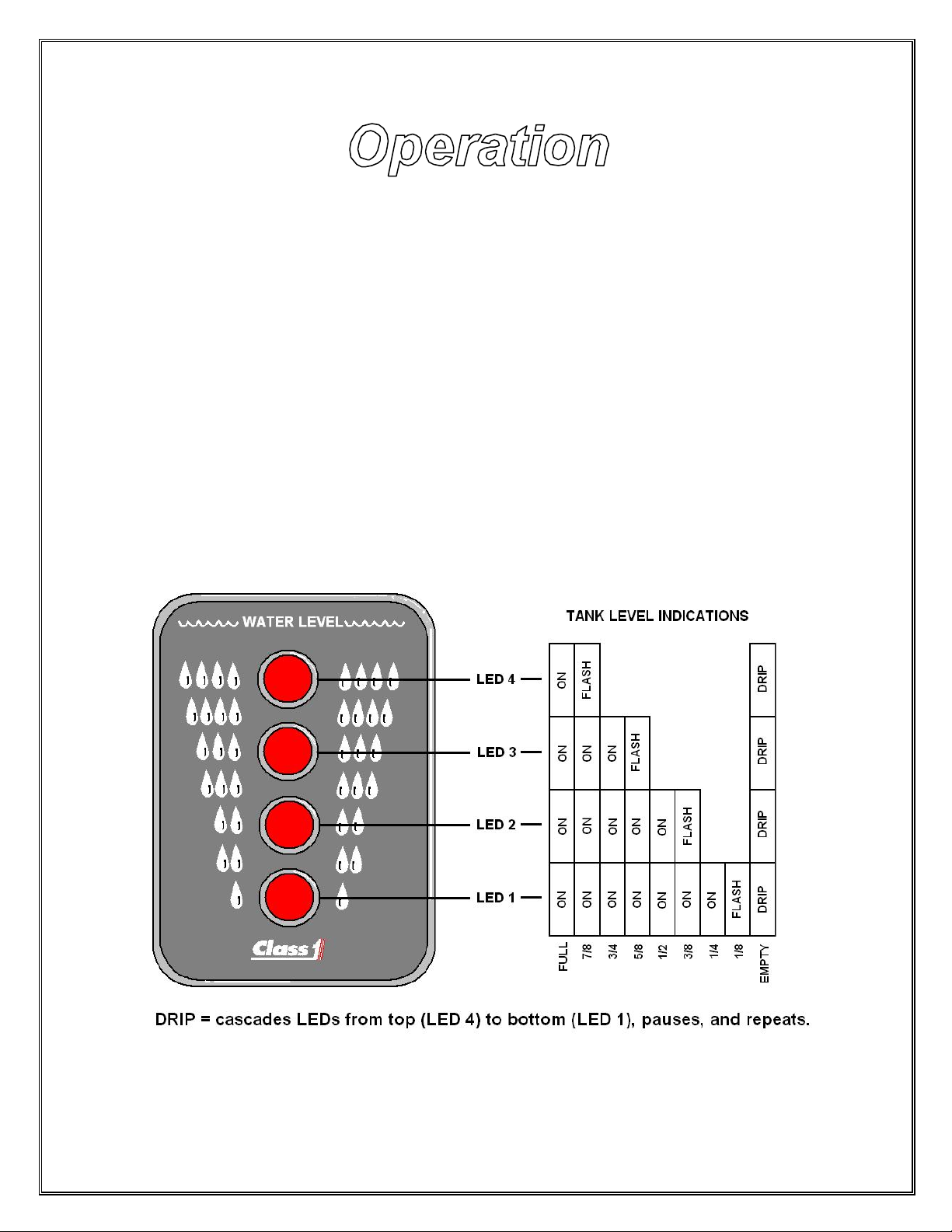
When the unit is first powered up the LEDs will cycle on individually starting with the
bottom LED (LED 1) and then the LEDs will show current status.
• A Master unit properly connected to a functioning transducer will display current
tank level information.
• A Master unit not connected to a pressure transducer will alternately flash the
bottom two LEDs.
• A Remote unit connected to a Master unit (through the 1-wire data line) will
mimic the Master unit’s LED condition and flash rate.
• A Remote unit not connected to a Master unit will alternately flash the upper two
LEDs and the lower two LEDs. This indicates a “no data” condition.
Level indications:
Intelli-Tank Manual (106759)092204 – 3 – Class 1
Page 4
Miscellaneous indications:
Condition LED 4 LED 3 LED 2 LED 1
Invalid calibration AlternaFLASH
EEPROM error AlternaFLASH AlternaFLASH
Signal voltage above
4.8V
Signal voltage below
.4V
Remote “NO DATA” AlternaFLASH AlternaFLASH
User Error (wave off) ON ON
4 quick cycles ON ON
The tank level has two flash rates: FAST (1.6Hz) and SLOW (.8Hz). AlternaFLASH flashes two lights
alternately at the SLOW flash rate.
“Wave off” pattern : two center LEDs, two outer LEDs flashing quickly for 8 cycles.
AlternaFLASH AlternaFLASH
AlternaFLASH AlternaFLASH
AlternaFLASH
Intelli-Tank Manual (106759)092204 – 4 – Class 1
Page 5
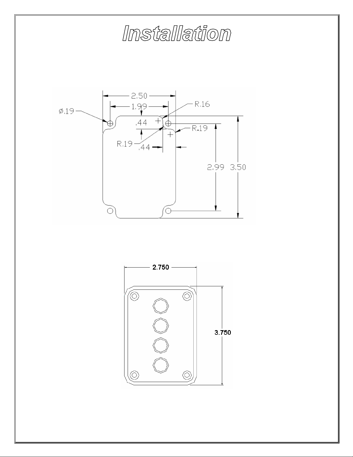
Intelli-Tank display The display requires a cutout as shown. The unit is water tight and may
be mounted in any location on the operator’s panel.
Outer bezel dimensions.
Before mounting the display and adhering the label insure that the unit is situated correctly (TOP is
UP). Refer to the drawing for orientation.
Intelli-Tank Manual (106759)092204 – 5 – Class 1
Page 6
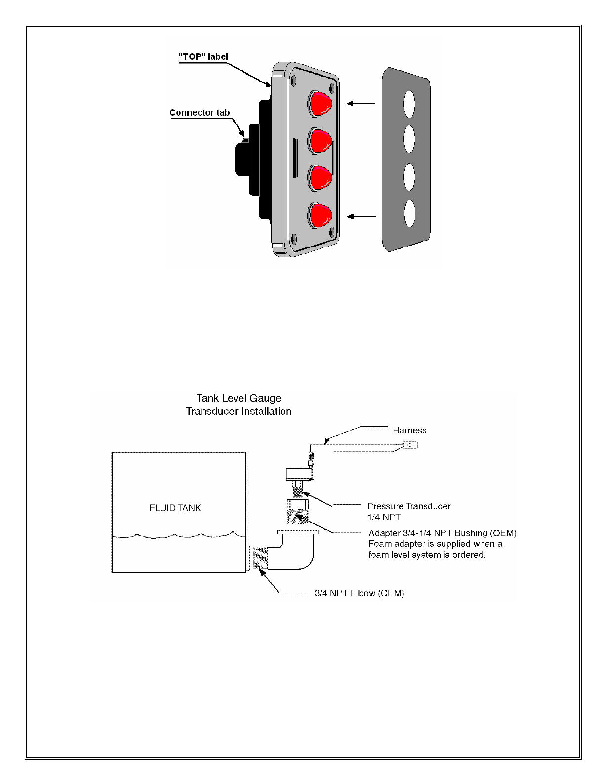
Pressure Transducer
The transducer has a ¼” NPT mount and must be mounted vertically as depicted to insure an
accurate reading.
Intelli-Tank Manual (106759)092204 – 6 – Class 1
Page 7

Power and Ground
It is imperative that a system utilizing Master and Remote tank level units connected by the 1-wire
data line have a common ground.
Pin 1 Vehicle power
Pin 2 Ground
Dim Function
The LEDs on the tank level unit can be dimmed to a user selectable dim setting by applying vehicle
voltage to the Dim display Input.
Pin 3 Dim display input (VIGN)
Transducer Connection
Pin 6 Sensor power (+5)
Pin 7 Sensor signal
Pin 8 Sensor ground
1-Wire Data Line
Pin 4 Master to Remote data transfer line
Intelli-Tank Manual (106759)092204 – 7 – Class 1
Page 8

Typical installation layout.
Intelli-Tank Manual (106759)092204 – 8 – Class 1
Page 9

The Intelli-Tank display can be calibrated three different ways: 2-point (level
calibration), 5-point and 9-point (vol ume calibration).
To enter calibration mode use a magnet and activate the magnetic switches in the
order of the appropriate password.
When a magnetic switch is activated the display will indicate which switch was activated
(Left = upper two LEDs, Right = bottom LED) for approximately half a second and then the
display will go blank. There is a limit of 2 seconds between switch activation’s before the
the unit reverts to normal operation.
Entering an invalid password will initiate a “wave off” pattern on the display. (Two center
LEDs, two outer LEDs flashing quickly for 4 cycles.)
Calibrate the unit by entering the desired point calibration –
2 point RLLR LLRL
5 point RLLR LRLR
9 point RLLR RLLR
Calibration mode can be exited at any time by activating the LEFT switch.
Intelli-Tank Manual (106759)092204 – 9 – Class 1
Page 10

2 Point Calibration
1. Enter the password RLLR LLRL. The unit will respond by flashing the two
center LEDs twice. The unit will then begin cascading the LEDs from top to
bottom (drip).
2. Make certain that the tank is EMPTY and then activate the RIGHT switch to
store that point. The unit will flash the top LED and then turn on all four LEDs.
3. Fill the tank and then activate the RIGHT switch . The unit will respond by
flashing the top LED then lighting the two center LEDs and then reverting to
normal operation by displaying FULL (all LEDs on).
5 Point Calibration
1. Enter the password RLLR LRLR. The unit will respond by flashing the two
center LEDs five times. The unit will then begin cascading the LEDs from
top to bottom (drip).
2. Make certain that the tank is EMPTY and then activate the RIGHT switch to
store that point. The unit will flash the top LED and then turn on the bottom
LED.
3. Fill the tank to the one-quarter tank point and then activate the RIGHT switch.
The unit will flash the top LED and then turn on the bottom two LEDs.
4. Fill the tank to the one-half tank point and then activate the RIGHT switch.
The unit will flash the top LED and then turn on the bottom three LEDs.
5. Fill the tank to the three-quarter tank point and then activate the RIGHT
switch. The unit will flash the top LED and then turn on all four LEDs.
6. Fill the tank to the full point and then activate the RIGHT switch. The unit will
respond by flashing the top LED then lighting the two center LEDs and then
reverting to normal operation by displaying FULL (all LEDs on).
9 Point Calibration
1. Enter the password RLLR RLLR. The unit will respond by flashing the two
center LEDs nine times. The unit will then begin cascading the LEDs from
top to bottom (drip).
2. Make certain that the tank is EMPTY and then activate the RIGHT switch to
store that point. The unit will flash the top LED and then begin flashing the
bottom LED.
3. Fill the tank to the one-eighth point and then activate the RIGHT switch. The
unit will flash the top LED and then turn on the bottom LED.
4. Fill the tank to the one-quarter tank point and then activate the RIGHT switch.
The unit will flash the top LED and then turn on the bottom LED and flash the
second LED.
5. Fill the tank to the three-eighths point and then activate the RIGHT switch.
The unit will flash the top LED and then turn on the bottom two LEDs.
Intelli-Tank Manual (106759)092204 – 10 – Class 1
Page 11

6. Fill the tank to the one-half point and then activate the RIGHT switch. The unit
will flash the top LED and then turn on the bottom two LEDs and flash the
third LED.
7. Fill the tank to the five-eighths point and then activate the RIGHT switch. The
unit will flash the top LED and then turn on the bottom three LEDs.
8. Fill the tank to the three-quarter point and then activate the RIGHT switch.
The unit will flash the top LED and then turn on the bottom three LEDs and
flash the fourth LED.
9. Fill the tank to the seven -eighths point and then activate the RIGHT switch.
The unit will flash the top LED and then turn on all four LEDs.
10. Fill the tank to the full point and then activate the RIGHT switch. The unit will
respond by flashin g the top LED then lighting the two center LEDs and then
reverting to normal operation by displaying FULL (all LEDs on).
Calibration data is saved in non -volatile EEPROM and the unit does not need
power to retain calibration data.
Calibration automatically makes the unit a master if the calibration is valid. An
invalid calibration is determined if any point is not at a higher level than the previous,
or if the transducer voltage falls outside of the valid minimum (.4V) or maximum
(4.8V) range. An invalid calibration is acknowledged by giving the “wave off” and if
this was a master unit previously will alterna-flash the outer two LEDs, while a
Remote will revert to Remote operation.
Intelli-Tank Manual (106759)092204 – 11 – Class 1
Page 12

Dimming the Display
The display can be dimmed by applying VIGN to pin 3 (Dim Display input). To
select the dim level of the display use the magnetic switches to enter the password
RLLR LLLR
all of the LEDs will come on. Hold the magnet against the RIGHT switch and the
display will either brighten or dim. Release the magnet and again hold it against the
RIGHT switch and the display’s brightness will move in the opposite direction.
When the dim level is at the desired point activate the LEFT switch. Each unit has
its own calibrated dim level and dim input.
Self Testing the Unit
The Tank Level can check its hardware for proper operation by entering the
password
RLLR LLRR
the unit will then cycle each LED on individually starting with the bottom LED and
then all LEDs will come on and begin flashing between full bright and the calibrated
dim level for 5 seconds. The display will then show the condition of the self test for 5
seconds.
A PASS condition is indicated when only the top LED (LED 4) is on.
A FAIL condition exists if LED 4 is off and any other LED is on.
LED 3 ON Memory failure.
LED 2 ON Data line error.
LED 1 ON Transducer signal line out of tolerance or shorted to
+5V.
LED 1 Flashing Transducer signal shorted to ground (too low).
If the self test password is used on a Master unit all Remote units will also perform
their self test.
Intelli-Tank Manual (106759)092204 – 12 – Class 1
Page 13

RLLR LLRL 2 point calibration
RLLR LRLR 5 point calibration
RLLR RLLR 9 point calibration
RLLR LLRR Self test
RLLR LLLL Configure unit as Remote unit
RLLR LLLR Configure dim level
Software revision check
Hold a magnet on the LEFT magnetic switch while powering the unit. The LEDs will
display the software revision. (Use the chart below to decipher).
Example. (LED 4 – OFF, LED 3 – ON, LED 2 – OFF, LED 1 – ON) = Ver 1.1
Intelli-Tank Manual (106759)092204 – 13 – Class 1
Page 14

Condition Evaluate
Bottom two LEDs
alternate flashing.
Unit fails self test,
LED 1 flashing.
Top two LEDs
alternate flashing.
Unit fails self test,
LED 1 on.
Middle two LEDs
alternate flashing.
Outer two LEDs
alternate flashing.
Bottom two and
Upper two LEDs
alternate flashing.
Check transducer wiring. Ensure +5V at pin A, ground at pin B and
at least .4V at pin C (Signal).
Check transducer wiring. Ensure +5V at pin A, ground at pin B and
no more than 4.8V at pin C (Signal).
Perform self test. If it fails with LED 3 on replace unit.
Try to recalibrate. If condition remains, check if transducer signal
voltage (pin C) changes as tank level increases. If it doesn’t,
replace transducer. If it does, verify depth of tank. It may be
impossible to calibrate a tank with a depth of less than 6 inches.
The unit is configured as a Remote. If it required to be a Master
then recalibrate. If the unit is required to be a Remote check Data
line (Pin 4) continuity and insure line is not grounded.
No LEDS on. Check power (Pin 1) and ground (Pin 2) connection.
Master Tank level
display does not
change when actual
tank level is
Check transducer wiring. Ensure transducer signal voltage (Pin C)
is varying. If it does, check for same signal changes at Pin 6 of
tank level connector (if it is not the same repair wiring). If signal is
good at both locations try re -calibrating.
changing.
Remote Tank level
display does not
follow Master
Perform self test. If self test is good, check pin 4 (data line) for
continuity and insure it is not shorted to ground or power. Insure
data line is not routed near noisy power or RF sources.
display.
Unit fails self test,
LED 2 on.
No passwords are
accepted.
Check pin 4 (data line) for continuity and insure it is not shorted to
ground or power.
If the display issues the “wave off” after entering a password,
insure the unit is installed upright. During power-up the display
should cycle on each LED individually starting with the bottom
LED.
Check that the left and right magnetic switches are recognized by
activating each switch and verifying that the associated LEDs
illuminate.
Intelli-Tank Manual (106759)092204 – 14 – Class 1
Page 15

Condition Evaluate
The bottom two
LEDs are on and
occasionally they
go out and the top
two flash and then
return to the bottom
two LEDs on (or
vice-versa).
(REMOTE).
The points
calibrated seemed
to have changed.
Unit will not dim
display.
Check for large noise spikes on the data line.
Insure that the unit’s ground potential is the same as the Master’s.
Insure that the data line is not chaffed and making contact with
other electrical wires.
Self test the unit to check for any malfunctions.
Check the pressure transducer for problems.
Recalibrate the unit and take a voltage reading from the transducer
(pin 7 on the unit’s connector) at each calibration point. When the
calibration points again look wrong check the voltages at those
points and determine if they are the same as the voltage reading
taken during calibration.
Insure the Dim input voltage on Pin 3 is at least 9V. Recalibrate
dim setting (RLLR LLLR). If unit does not dim LEDs while in dim
calibrate mode, replace unit.
Intelli-Tank Manual (106759)092204 – 15 – Class 1
Page 16

Intelli-Tank Manual (106759)092204 – 16 – Class 1
 Loading...