

Page 1

Intelli-Tank
High current 4 light remote
driver module
with auto refill and alarm
Contents ………………………………………………….. 1
Overview ………………………………………………….. 2
Operation ………………………………………………….. 3
Installation and
Wiring
Specifications ………………………………………………….. 8
Troubleshooting ………………………………………………….. 9
………………………………………………….. 5
Intelli-Tank Manual (106759) 12-15-03 – 1 – Class 1
Page 2

The Intelli-Tank Driver module utilizes the 1-wire data line to receive tank level
information from a Master 4 light tank level display (C1-PN 106299 or 106296)
and then mimics the Master’s display with its high current outputs. The module
also incorporates an auto-refill function that, when activated, turns on the fill
output at less than ¾ tank level and turns it off when the tank reaches the FULL
point. An alarm output activates when tank level reaches ¼ or if data from the
Master is lost for over 10 seconds.
Basic parts:
Driver module C1 – PN 106877 12/24V
Installation Harness C1 – PN 106692
User Manual C1 – PN 106759
Prerequisite parts:
Master 4 light tank
level display C1 – PN 106299 12V
106292 24V
Accessories:
Remote dash indicator C! – PN 106878
Modes of Operation:
Normal The module receives tank level data from the Master and mimics
the Master’s display with the high current outputs.
Auto-Fill When the level of the tank is below ¾ the fill output comes on and
remains on until the Master display indicates FULL.
Intelli-Tank Manual (106759) 12-15-03 – 2 – Class 1
Page 3
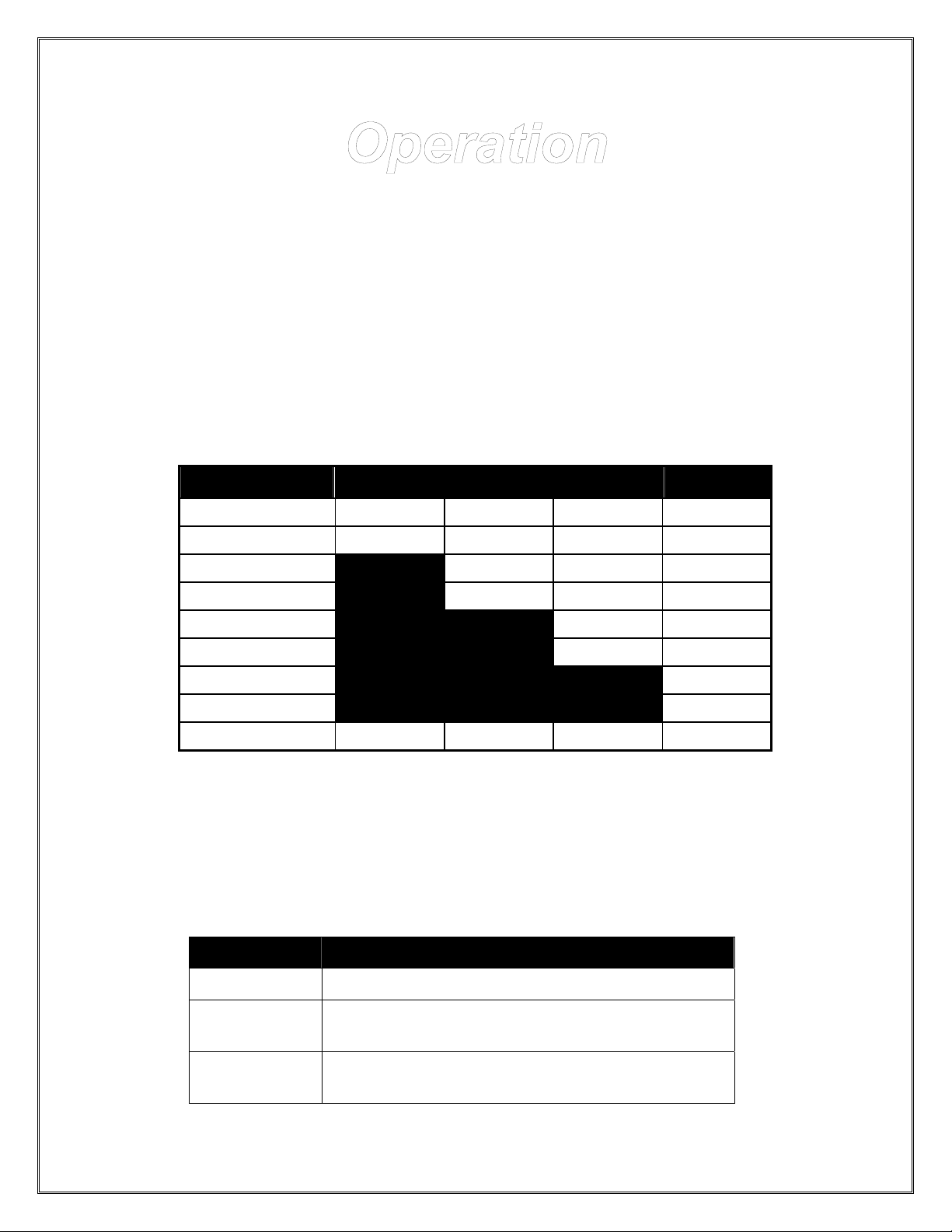
When the unit is first powered up the lights will cycle on individually starting with
the EMPTY (output 1) light and then the lights will show the current status.
• A Module connected to a Master unit (through the 1-wire data line) will mimic
the Master unit’s LED condition and flash rate.
• A Module not connected to a Master unit will alternately flash the upper two
lights and the lower two lights. This indicates a “no data” condition.
Level indications:
LEVEL output 4 output 3 output 2 output 1
7/8 < LVL <= F ON ON ON ON
3/4 < LVL <= 7/8 FLASH .8Hz ON ON ON
5/8 < LVL <= 3/4 ON ON ON
1/2 < LVL <= 5/8 FLASH .8Hz ON ON
3/8 < LVL <= 1/2 ON ON
1/4 < LVL <= 3/8 FLASH .8Hz ON
1/8 < LVL <= 1/4 ON
1/16 < LVL <= 1/8 FLASH .8Hz
E <= LVL <= 1/16 FLASH 1.6Hz FLASH 1.6Hz FLASH 1.6Hz FLASH 1.6Hz
Auto-Fill Function
Auto-fill mode is active when the auto-fill select input (pin 8) is grounded. The
auto-fill status light output (pin 2) indicates the current status of this mode and is
capable of driving positive voltage to 250mA.
Status Light Condition
On
Flashing
Off
Auto-fill mode selected and is in standby
Auto-fill mode selected and is currently filling
(refill output is active).
Auto-fill mode de-selected or error condition is
present.
Intelli-Tank Manual (106759) 12-15-03 – 3 – Class 1
Page 4

The auto-fill function will energize the fill output when the tank level is at or below
¾ and de-energize when the Master display reads FULL. Auto-fill will also deenergize the fill output and turn off the auto-fill status light if there is no data
being received on the data line from the Master display (serial error) or if a
transducer error high or low (range error) is encountered.
4 Outputs for the level lights
Four outputs are available to drive external lights to indicate tank level. These
are positive voltage outputs are capable of 7.5A each (Full light is output 4).
Alarm and alarm silence
The alarm output (pin 3) activates when the tank level falls to below ¼ tank or 10
seconds after a data line problem exists. The alarm output is a positive voltage
output capable of 250mA. The alarm silence input (pin 5) will turn the alarm off
during any alarm circumstance. The alarm silence activated by a momentary
ground input.
1-wire serial interface
The 1-wire serial interface is the link between the master tank level module and
any other remote modules. If the output driver module loses the serial link all
outputs will be deactivated and then the output lights will alternate flashing the
upper two lights and the lower two lights, and the auto-fill function will be
deactivated. After 10 seconds in this serial failure condition the alarm will sound
(it can be turned off with the alarm silence switch).
Dim level light outputs
The output lights are set to the dim condition (50% duty cycle) when a ground is
input on pin 6.
Module LED indicators
There are 3 LEDs on the front of the remote driver module. The RED LED
indicates that the circuit board has power. The YELLOW LED indicates the
power stud has power. The GREEN LED indicates the condition of auto-fill mode
and will react the same as the auto-fill status light output (pin 2).
Intelli-Tank Manual (106759) 12-15-03 – 4 – Class 1
Page 5
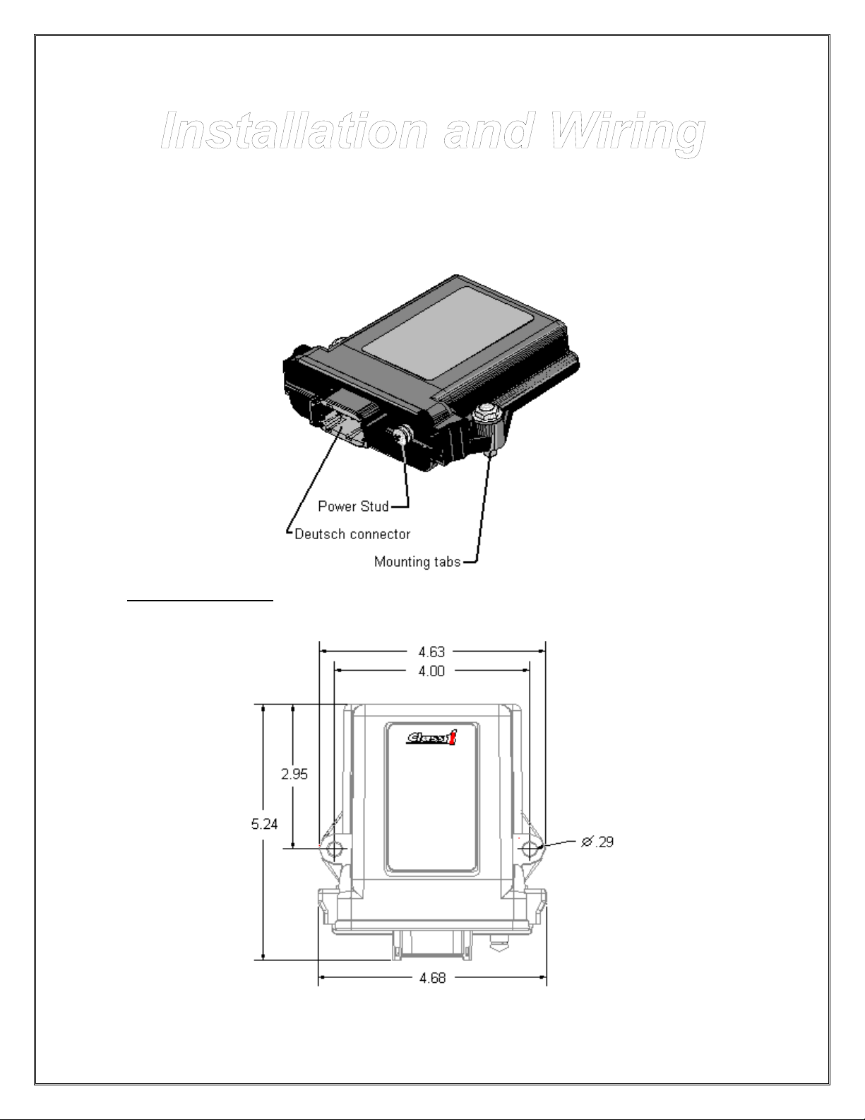
Driver Module The module is water tight and can be mounted any place away from
large RF noise generators.
Mounting dimensions (inches)
Intelli-Tank Manual (106759) 12-15-03 – 5 – Class 1
Page 6

Typical installation
Connector detail
Intelli-Tank Manual (106759) 12-15-03 – 6 – Class 1
Page 7

Power and Ground
It is imperative that the driver module and the Master tank level have a common ground.
Stud Vehicle power (12/24VDC)
Pin 12 Ground
High Current Outputs (7.5A)
Pin 1 Output 1 (1/4)
Pin 11 Output 2 (1/2)
Pin 9 Output 3 (3/4)
Pin 7 Output 4 (FULL)
Auto-Fill components
Pin 2 Auto-Fill status light output (+V)
Pin 4 Fill output (+V)
Pin 8 Auto-Fill select input (ground = auto-fill ON)
1-Wire Data Line
Pin 10 Data transfer line
Alarm functions
Pin 3 Alarm output (+V)
Pin 5 Alarm silence (ground = silence active)
Dim lights
Pin 6 Dim lights input (ground = dim active)
Intelli-Tank Manual (106759) 12-15-03 – 7 – Class 1
Page 8
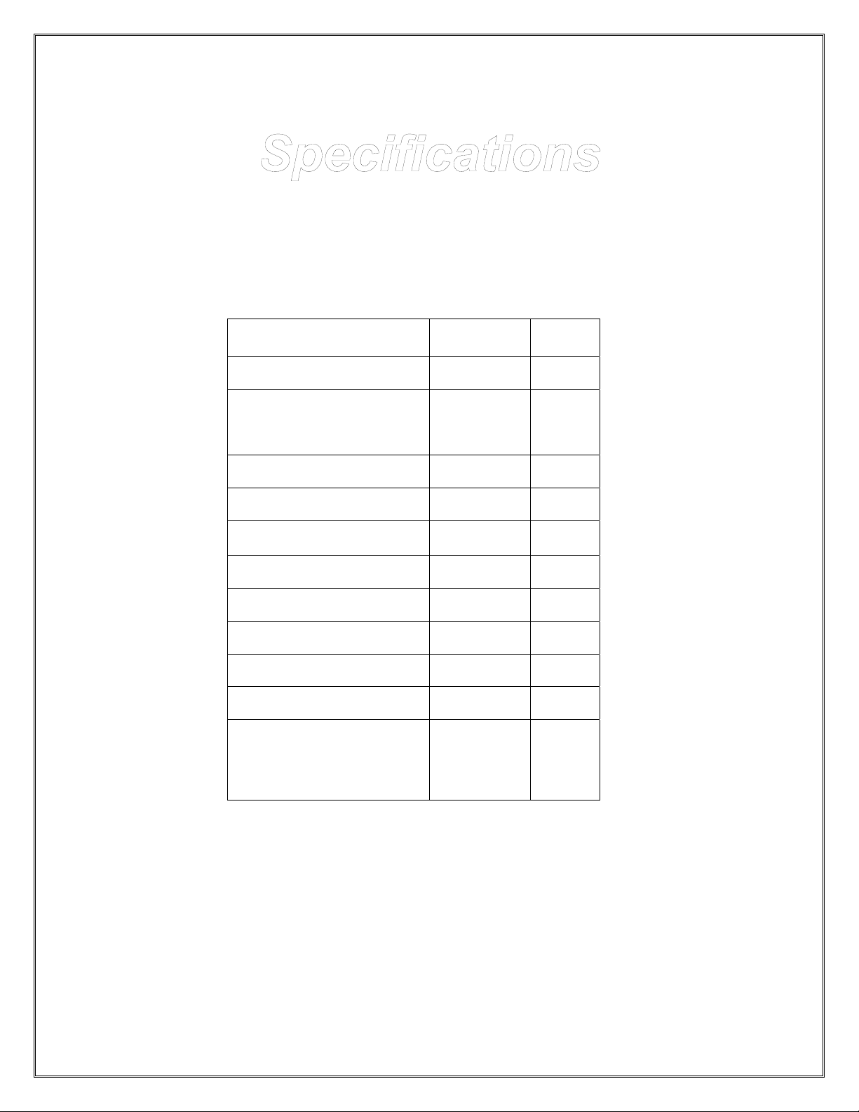
Parameter Value Unit
Input voltage
Current nominal:
No outputs active
@ 13.8VDC 44 mA
@ 27.6VDC 55 mA
Operating temperature
Maximum current:
Alarm output 250 mA
Auto-fill status light output 250 mA
Fill output 250 mA
External light outputs 7.5 A
Maximum difference of
potential between grounds
(master and remote driver)
+10 to +32 VDC
-40 to 85
1
°C
V
Intelli-Tank Manual (106759) 12-15-03 – 8 – Class 1
Page 9

Condition Evaluate
Bottom two lights
alternate flashing.
Top two lights
alternate flashing.
Bottom two and
Upper two lights
alternate flashing.
Bottom and top
lights alternate
flashing (center two
are off)
No lights are on. Unit is not powered or external lights are not connected properly.
Master tank level display’s transducer signal voltage is below
.4VDC.
Check transducer wiring to master tank level display.
Master tank level display’s transducer signal voltage is above
4.80VDC.
Check transducer wiring to master tank level display.
Remote driver module is not receiving data from the master tank
level display.
Check for continuity on the data line (pin 10) to the master tank level
display and that the grounds are common between units (there
should be less than 1V difference of potential). Insure the master
tank level display is functioning properly.
Master tank level display has an invalid calibration.
Recalibrate Master display.
Check power (Stud) and ground (Pin 12) connection for proper
voltage.
Unit will not dim
lights.
Alarm will not
silence.
Auto fill not
functioning
Intelli-Tank Manual (106759) 12-15-03 – 9 – Class 1
Check for proper ground input signal to pin 6 when activating the
dim input switch.
Check for proper ground input signal to pin 5 when activating the
alarm silence switch.
Check for proper ground input signal to pin 8 when activating the
auto-fill select switch.
Insure remote driver is displaying same information as master tank
level display.
 Loading...