

Page 1

ESM_III
Standard Features .................................................................2
Display Panel .........................................................................3
System Configuration ............................................................4
Main Battery Only Configuration............................................5
Main and Isolated Battery Configuration................................6
Electrical System Manager II.................................................7
Specifications .................................................................... 8-9
Models and Functions .........................................................10
Sample Circuits ..............................................................11-12
Troubleshooting ...................................................................13
Notes ...................................................................................14
1
Page 2

Standard Features
Sequence
All outputs sequence on (T1-T7) and off (T7-T1).
Automatic Load Reset
Any load which has been shed will remain off for a minimum of two minutes.
The loads will be controlled back on (unshed) by the system when the system voltage rises above the unshed level.
Shed loads can be turned on immediately by turning off the load management enable input.
Over-Voltage Indicator
The system manager continually monitors the system voltage and will activate output T15 ( SW1 switch 3 ON) when it detects that the system voltage
has increased above 15.0 volts. The system will not react to the spurious
voltage transients which may exist in the electrical system as loads and devices are cycled.
Fast Idle Control
The system manager is capable of becoming a part of a system which controls a fast idle device. The fast idle output T15 (SW1 switch 3 OFF) will
activate whenever the system voltage falls to 12.8 volts or below.
The output will deactivate if the system manager is reset, load management
disabled or when the system voltage recovers above 12.8 volts.
This output should be utilized with appropriate safety interlocks.
Battery Warning
The Battery Warning feature is a special output (T 8) which indicates that the
electrical system voltage has fallen below 11.9 VDC.
The Class 1 system manager continuously monitors the electrical system.
This output can be wired to a warning device that requires less than 250 mA
or to a relay if higher current devices are used.
Isolated Battery Warning
This is an optional configuration used when an isolated (auxiliary) battery
needs to be monitored. J9 must be in the ISO BATTERY position and SW1
switch 1 must be turned ON. T7 becomes the Isolated Battery Warning output
and activates when the isolated battery voltage falls below 11.9 VDC.
This output can be wired to a warning device that requires less than 250 mA
or to a relay if higher current devices are used.
105519 08172000
2
Page 3
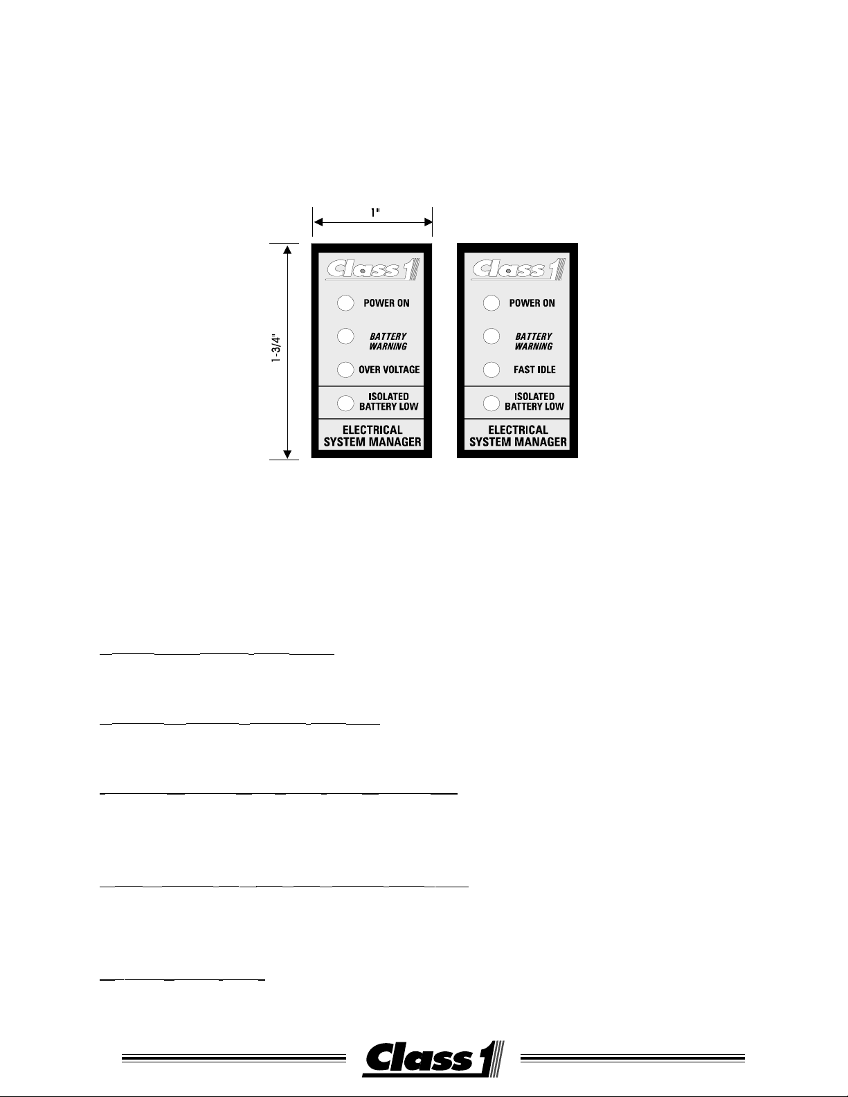
Display Panel
STANDARD PANEL DISPLAY
The Class1 Electrical System Manager is supplied with an indicator panel.
The indicator panel is designed to fit in a standard rocker switch cutout ( 7/8” x 1-1/2”).
The indicator panel consists of four LED’s:
POWER ON (GREEN WIRE) T13
This LED illuminates when power is applied to the System Manager.
BATTERY WARNING (YELLOW WIRE) T8
This LED activates when the system voltage drops below 11.9 VDC.
ISOLATED BATTERY LOW (BLUE WIRE) OPTION T7
This LED illuminates when an auxiliary battery voltage drops below 11.9
VDC.
OVER-VOLTAGE OR FAST IDLE (BROWN WIRE) T15
This LED illuminates when system voltage drops below 12.8 VDC or rises
above 15.0 VDC as configured by SW1 switch 3.
GROUND (BLACK WIRE)
Connected to system ground.
3
Page 4
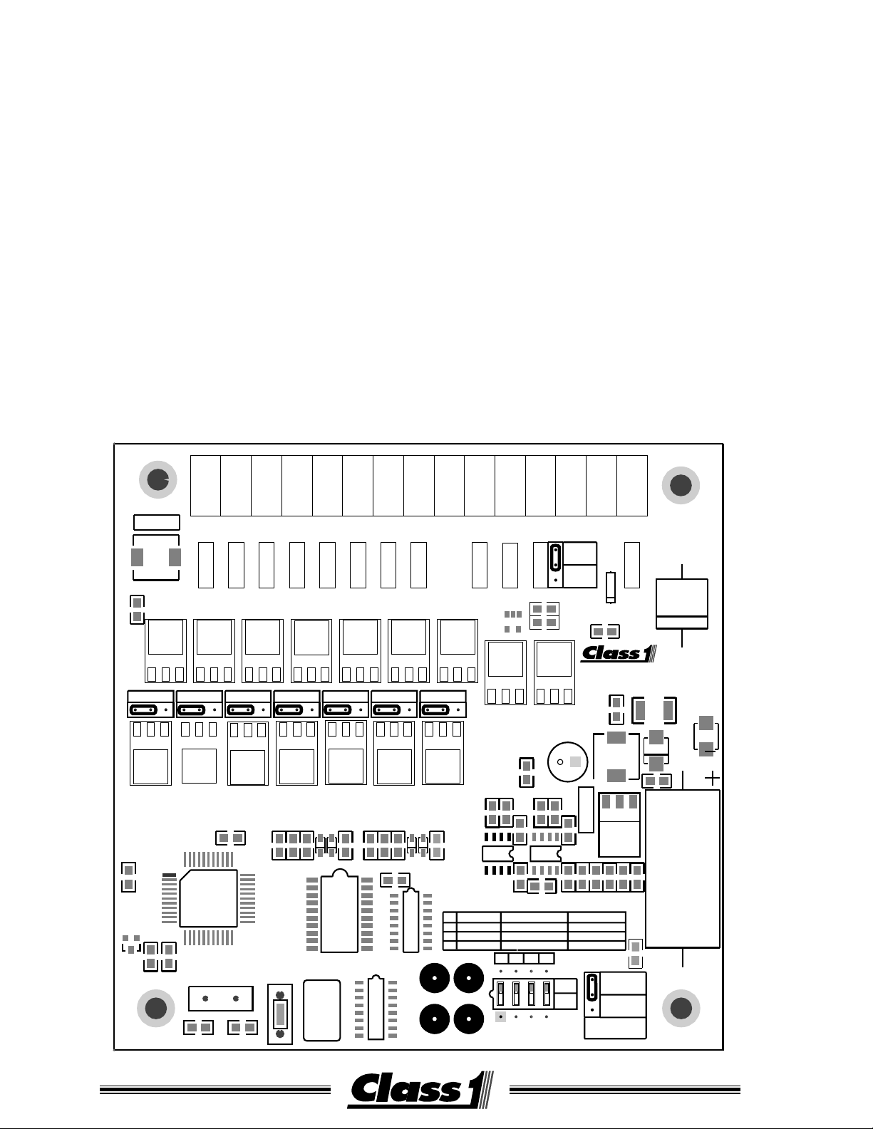
System Configuration
The Electrical System Manager is configured by the use of a 4 position DIP Switch SW1
and 9 shunts (jumpers) J1 - J9.
SW1
switch OFF ON
1 Main Battery Main and Isolated Batteries
2 Shed T1-T7 Shed T7-T1
3 Fast Idle Overvoltage
4 Shed all Don’t shed T1 or T2
J1 controls polarity of the Master Switch input.
J2-J8 control the polarity of output T1 through T7
J9 controls whether T12 is tied to the Master Switch input T10 or independent for an
Isolated Battery Input.
<=-CAUTION-=>
When J9 is in the MASTER SWITCH position T12 is tied directly to T10. A direct short
circuit will occur if an Isolated Battery Input is at T12 and a ground Master Switch input
is at T10.
<=-CAUTION-=>
T5T4T3T2T1
T6
FT13
L2
FB2
J2
GND POS
R11
U2
J3 J4 J5 J6 J7 J8
Out-1 Out-2 Out-3 Out-4 Out-5 Out-6 Out-7
GND POS
U1
C2 C1
C13 C12
C7
XT1
GND POS GND POS
U19U17
R7 R6R5
SW2
GND POS
U3
REV B
GMC / AMS
04-27-2000
P.N. 104702
GND POS GND POS
R8
C11C10 C9C8
C3
RSP2
U22U21U20U18U16
D7 D6D5 D4
RSP1
U13U12U11U10U9U8U7
1
2
3
4
SHED O/I
TP1 TP2
TP3 TP4
BATTS
SHED
T15
R14
U4
R13
1
SW1
J9
U15U14
R21
R16
R18
R12
U24
C16
R17
ON OFF
MAIN/ISO
7 1
OVER VOLTS
NO
234
TB 12
INPUT
MASTER
SWITCH
ISO
BATTERY
R10
R9
PHONE 352-629-5020
FAX 352-629-2902
http://www.class1.com
C15
+
R15
FT15
U23
R3 R2
C17
MAIN
1 7
FAST IDLE
YES
J1
ON
OFF
D3
C4
OCALA ,FL
FB1
L1
U5
R4
C18
GROUND
POSITIVE
Master
Switch
T15T14T13T12T11T10T9T8T7
FT14FT12FT11FT10FT8FT7FT6FT5FT4FT3FT2FT1
D2
F1
Z1
D1
C5
R19
R20
C14
105519 08172000
4
Page 5
Main Battery Only Configuration
SW1 switch 1 OFF.
All seven load control outputs can be sequenced and shed. These outputs
are at terminals #1 through #7 (T1 - T7). One method of wiring is shown
below.
T 15
T 14
Fast Idle
OverVoltage
T 13
T 12
T 11
Load Manage
Ignition Switch
+
-
Main Batt
T 10
T 9
Enable Switch
Battery Warning
Master Switch
Relay 7
T 8
T 7
Load SW 7
T 6
T 5
T 4
T 3
T 2
T 1
Dash
Load SW 1
Load
Relay 1
Switches
Relays
5
Page 6

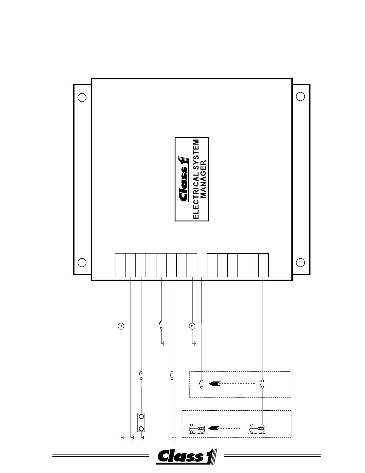
MAIN AND ISOLATED BATTERY CONFIGURATION
ELECTRICAL SYSTEM
MANAGER
Over Voltage Lt
Ignition Sw
Main Batt
Isolated Batt
Shed Enable Switch
Master Sw
connected only
when ignition on
Rly 1
Rly 6
Load Sw 1
Load Sw 6
Dash Switches
Load Relays
Battery Warning Lt
Isolated Batt Lt
T 1
T 9
T 5
T 13
T 3
T 11
T 7
T 15
T 2
T 10
T 6
T 14
T 4
T 12
T 8
Jumper J9 placed in ISO BATTERY position and SW1 switch 1 is turned ON.
The system manager will operate in main and isolated battery mode.
A separate input for the isolated battery is located at T12 and an output for
Isolated Battery Low is located at T7.
This provides for six load control outputs (T1-T6) which can be sequenced
and shed.
105519 08172000
6
Page 7

Electrical System Manager II
Relay Coil Input
Relay LED©s
The Electrical System Manager II is equipped
with 8 Printed Circuit Board Relays mounted in
an enclosure with the load manager. The relay coil input tab should be grounded for normal installations. The common and output tabs
on each relay readily allow for custom installations.
COM
COM
COM
COM
1
N O
N C
2
N O
N C
3
N O
N C
4
N O
N C
5
N O
COM
1
2
3
4
5
6
7
8
COM
COM
N C
6
N O
N C
7
N O
N C
8
N O
COM
N C
7
Page 8

SPECIFICATIONS
OPERATING VOLTAGE
7.5 to 20 Volts DC
OUTPUTS
High Side Drivers Vmain @ 0.5 amp (source)
Low Side Drivers Ground @ 0.5 amp (sink)
ISOLATED BATTERY INPUT
0 to 20 Volts DC
TRANSIENT SUPPRESSION
Outputs are protected against thermal overload, direct shorts and transient
spikes from -50 to 60 Volts DC.
LOAD CONTROL
Loads will be sequenced on whenever the Master Switch is activated.
The System Manager will control loads and the high idle function only when
the Load Manage Enable input (terminal #11) is active.
Loads are shed from lowest priority to highest priority, T-1 to T-7, unless SW1
switch 2 is turned ON. Then they shed T-7 to T-1.
The voltage points are respectively:
Shed Unshed SW1-2
T1 12.4 12.8 T7
T2 12.2 12.4 T6
T3 12.0 12.2 T5
T4 11.8 12.0 T4
T5 11.4 11.6 T3
T6 11.0 11.4 T2
T7 10.8 11.2 T1
If SW1 switch 2 is ON, then the order is reversed as shown in SW1-2 column.
If SW1 switch 4 is ON, then T1 and T2 will not shed.
Voltage must drop below the shed point for 60 seconds for a load to shed and
voltage must be above the shed point for 600 seconds for a shed load to
unshed.
MANUAL RESET
Toggling the Master Switch off for more than 2 seconds will cycle all loads off.
The system will return to normal operation when the Master Switch is toggled
back to the on position.
105519 08172000
8
Page 9

SPECIFICATIONS
TERMINAL BLOCK #15
This output becomes active for the overvoltage light (high voltage) or for high
idle control (low voltage) dependent on the setting of SW1 switch 3 .
OVER-VOLTAGE INDICATOR
Activates at and above 15.0 VDC and deactivates below 15.0 VDC.
HIGH IDLE CONTROL
The output will activate when the voltage drops below 12.8 VDC for more
than 1 minute. The output will remain ON for a minimum of 5 minutes
until the voltage exceeds 12.8 VDC.
NOTE: This output must only be used in conjunction with the appropriate
safety interlocks for the intended application.
AUXILIARY BATTERY
When an auxiliary battery is present and the system is configured for it, The
System Manager will monitor the auxiliary battery. Output (TB #7) is turned
on when the battery voltage drops below 11.9 VDC for more than 10 seconds. The output will remain on until the isolated battery voltage is greater
than 11.9 VDC. If the main battery bank voltage exceeds 13 VDC, the output
will deactivate and the system will then recheck the isolated battery voltage
after a short delay. This allows the system to become part of a battery separation solenoid system.
and
NOTE: When configured to monitor a second battery source, only 6 loads
can be controlled as output #7 is utilized for the isolated battery
indicator. All other functions are unchanged.
LOW VOLTAGE WARNING OUTPUT
Output from T8 is disabled when the monitored voltage is above 11.9 VDC.
At and below this level, the output will turn on to indicate low voltage.
9
Page 10
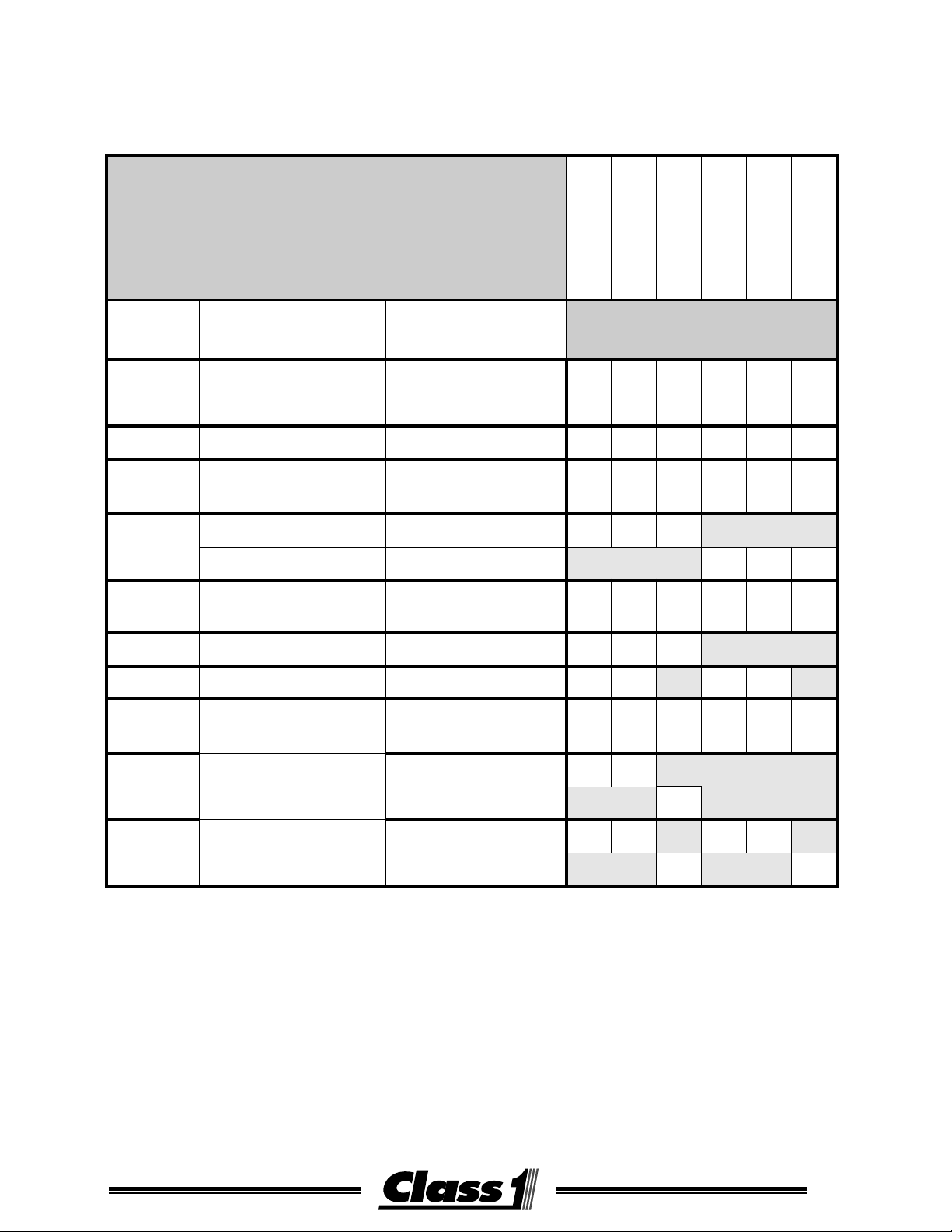
MODELS AND FUNCTIONS
Existing System Managers
and System Manager II’s
11111
11111
11111
11111
11111
11111
0
0
0
0
0
0
0
0
1
0
1
1
6
7
0
7
0
1
3
5
8
6
3
1
3
6
4
7
8
9
lanimreTlanimreT
lanimreTlanimreT
lanimreT
colB
kkkkk
noitcnuFnoitcnuF
noitcnuFnoitcnuFO/IO/I
noitcnuF
O/IO/I
O/I
ytiraloPytiraloP
ytiraloPytiraloP
ytiraloP
51thgilegatlovrevOtuptuOevitisoP
lortnocelditsaFtuptuOevitisoP
41dnuorGmetsyStupnIdnuorG
31
21yrettabdetalosItupnIevitisoP
11
01hctiwSretsaMtupnIdnuorG
9CN
8
7woLyrettaBdetalosItuptuOevitisoP
niam(noitingI
)yrettab
hctiwSretsaMtupnIevitisoP
elbanEdehS
)tnemeganaMdaoL(
woLyrettaB
thgiLgninraW
tupnIevitisoP
tupnIdnuorG
tuptuOevitisoP
tuptuOdnuorG
XXXXXXXXXXXXXXXXXXXXXXXXXXXXXX
XXXXXXXXXXXXXXXXXXXXXXXXXXXXXX
XXXXXXXXXXXXXXXXXXXXXXXXXXXXXX
XXXXXXXXXXXXXXXXXXXXXXXXXXXXXX
XXXXXXXXXXXXXXX
XXXXXXXXXXXXXXX
XXXXXXXXXXXXXXXXXXXXXXXXXXXXXX
XXXXXXXXXXXXXXX
XXXXXXXXXXXXXXXXXXXXXXXXXXXXXX
XXXXXXXXXX
XXXXX
1-7
SHUNT AND S WITCH SETTINGS TO MATCH EXISTING UNITS FOR REPLACEMENT PURPOSES.
MASTER OUTPUT ISO MAIN SHED1-7 FAST IDLE SHED 0 & 1
1daoL-7daoLtuptuOevitisoP
tuptuOdnuorG
MASTER ISO 7-1 OVERVOLTAGE
XXXXXXXXXX
XXXXXXXXXX
XXXXX XXXXX
Model J1 J2-8 J9 SW1-1 SW1-2 SW1-3 SW1-4
100633 GND POS ISO OPT OFF OPT OFF
101084 GND GND ISO OPT OFF OPT OFF
100767 POS POS MSTR OPT ON OPT ON
101119 POS GND MSTR OPT ON OPT ON
OPT indicates the switch should be positioned to match current operation.
105519 08172000
10
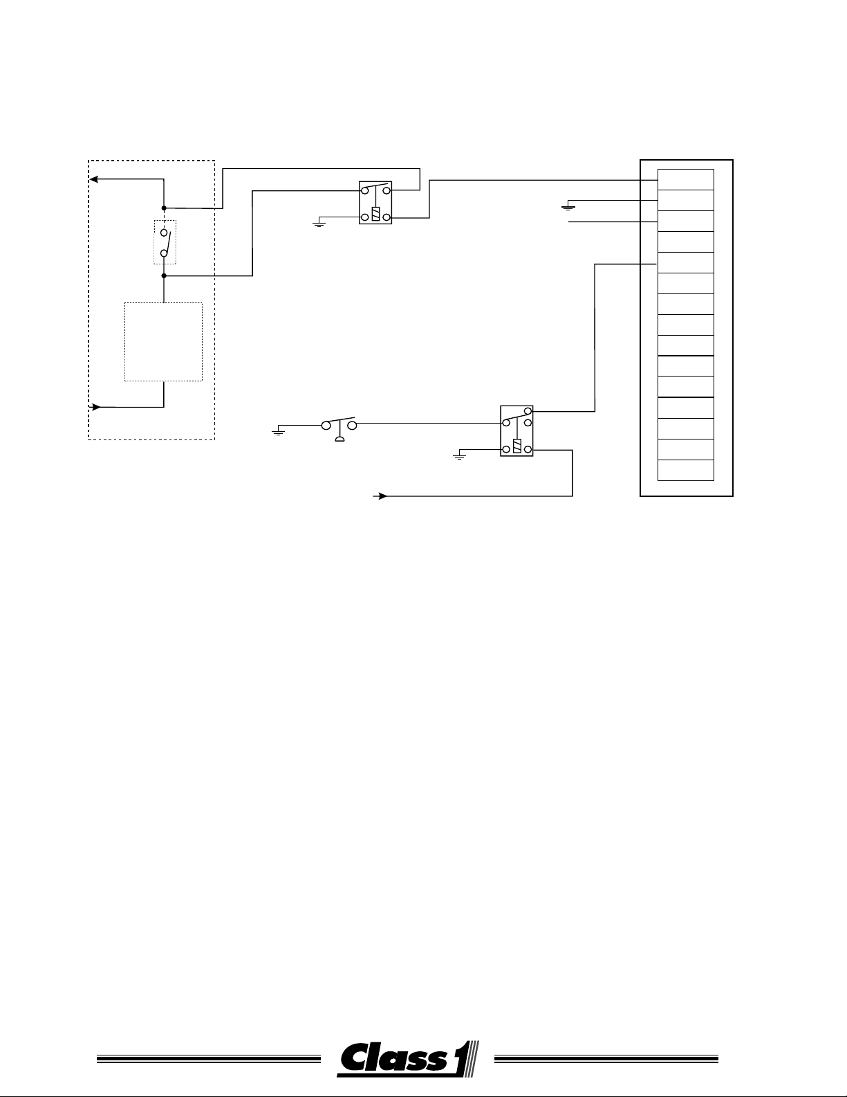
Page 11

Note:
SAMPLE CIRCUITS
A/C Control Circuit
Aux Control
Relay
As A/C control circuits vary by vehicle, the circuit shown is
representative only of one method which can be utilized to
interrupt the A/C control circuit. It is the responsibility of the
installer to utilize properly rated relays or circuit breakers in
the installation.
The loading on output #15 should not exceed 0.5 amps.
Alternator
Starter
Ignition Sw
BATT SEPARATOR SOLENOID
POWER TO VEHICLE LOADS
+
-
+
-
+
-
+
-
+
-
+
-
Batt Ground
POWER TO SEPARATED LOADS
TB#15
TB#14
TB#13
TB#12
TB#11
TB#10
TB#9
TB#8
TB#7
TB#6
TB#5
TB#4
TB#3
TB#2
TB#1
11
Page 12
Fast Idle
Switch
OEM Fast Idle
Interlocks
OEM Fast
Idle Circuit
SAMPLE CIRCUITS
Ground
Relay
PSI Switch closed
when Park Brake set
Ignition
Shed Enable
Relay
TB#15
TB#14
TB#13
TB#12
TB#11
TB#10
TB#9
TB#8
TB#7
TB#6
TB#5
TB#4
TB#3
TB#2
TB#1
Signal From Brake Lights
Automatic FAST IDLE CIRCUIT, disabled when service brake is applied
12
105519 08172000
Page 13
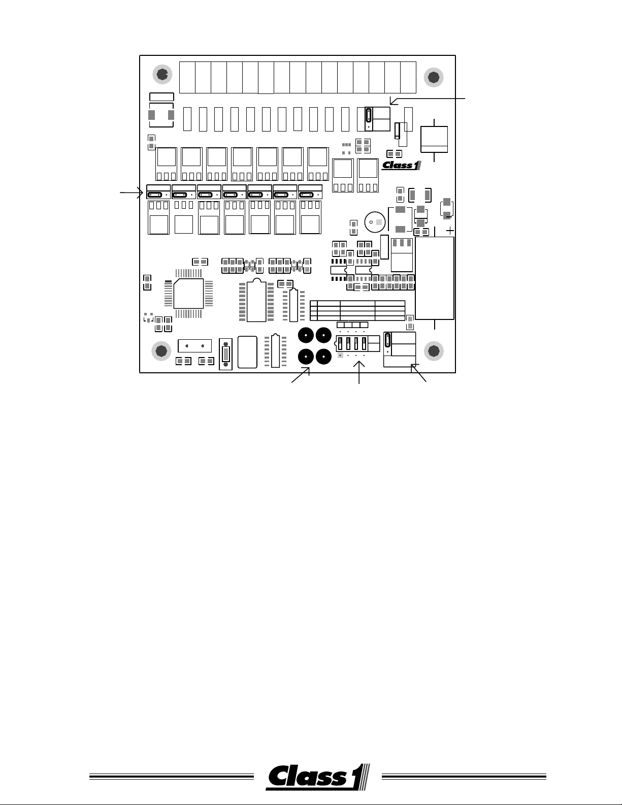
TROUBLESHOOTING
Output Polarity
Jumpers
T5T4T3T2T1
T6
FT13
L2
FB2
Out-1 Out-2 Out-3 Out-4 Out-5 Out-6 Out-7
J2
J3 J4 J5 J6 J7 J8
GND POS
R11
U2
U1
C2 C1
GND POS
C7
XT1
C13 C12
GND POS GND POS
U19U17
SW2
R7 R6R5
P.N. 104702
GND POS
U3
REV B
GMC / AMS
04-27-2000
GND POS GND POS
C11C10 C9C8
R8
C3
RSP2
D7 D6D5 D4
RSP1
FT9
U13U12U11U10U9U8U7
U22U21U20U18U16
1
2
3
4
TP1 TP2
TP3 TP4
BATTS
SHED
T15
SHED O/I
R14
R13
1
SW1
U4
U15U14
R21
R18
R12
U24
C16
R17
ON OFF
MAIN/ISO
7 1
OVER VOLTS
NO
234
BATTERY
J9
R10
R9
R16
R15
U23
C17
ON
OFF
TB 12
INPUT
MASTER
SWITCH
ISO
C4
OCALA ,FL
PHONE 352-629-5020
FAX 352-629-2902
http://www.class1.com
L1
C15
+
U5
FT15
C18
R3 R2
MAIN
1 7
FAST IDLE
YES
J1
Master
Switch
FT14FT12FT11FT10FT8FT7FT6FT5FT4FT3FT2FT1
D3
FT8
FB1
R4
GROUND
POSITIVE
T15T14T13T12T11T10T9T8T7
Terminal 12
Control Jumper
D2
F1
D1
C14
C5
R19
R20
Caution: If this jumper is in
the Master Switch position,
it is tied directly to Terminal 10
Z1
Voltage Test Points:
TP1 System Voltage
TP2 Filtered Voltage
TP3 +5 VDC
TP4 Ground
SW1
configuration switch
Master Switch
Polarity Jumper
Visual check
Check jumpers J1-J9 and ensure that they are in the correct position for the application.
Check switch SW1 that 1-4 are in the correct postion for the operation desired.
Voltage Supply check
Check for system voltage between terminals T14 (ground) and T13 (12VDC). Check for system voltage betweenTP4 (ground) and TP2 (12 VDC). These should be within 0.5 VDC.
Check for 5 VDC between TP4 and TP3 (+5 VDC).
These voltages must be present for the system to operate.
Master Switch check
Verify that J1 is in the proper position for the Master Switch you are using. Check for the input
at T10.
This controls load sequencing on and off.
Load Manage Enable check
Check for a ground at T11.
This inputs allows loads to shed and the Fast Idle output.
Output Test
Verify that jumpers J2 through J8 are in the correct position. With power on and a Master
switch input there should be either 12 VDC or Ground on T1 through T7 dependent on the the
position of J2-J8.
13
Page 14

NOTES
14
105519 08172000
 Loading...