

Page 1

Contents
Table of Contents
Contents ........................................................................................................... 1
Network .........................................................................................................2-3
Hardware....................................................................................................... 4-5
Addresses ........................................................................................................ 6
Logic................................................................................................................. 7
Example ........................................................................................................... 9
Power Modules ......................................................................................... 10-11
Motor Control ................................................................................................. 12
Solid State PDM ............................................................................................. 13
Switch Modules .........................................................................................14-15
USM 103383 .................................................................................................. 16
System Logic..................................................................................................17
MNGT Data .................................................................................................... 18
MPLX Data ..................................................................................................... 19
INTK Data....................................................................................................... 20
Fault Menu ..................................................................................................... 21
Module Menu ................................................................................................. 22
I/O-VOC Menu................................................................................................ 23
ENG Menu ..................................................................................................... 24
MNGT Menu ................................................................................................... 25
FILE Menu...................................................................................................... 26
USM 103383 .................................................................................................. 28
Make Card...................................................................................................... 29
Display ......................................................................................................30-31
1
Page 2
Network
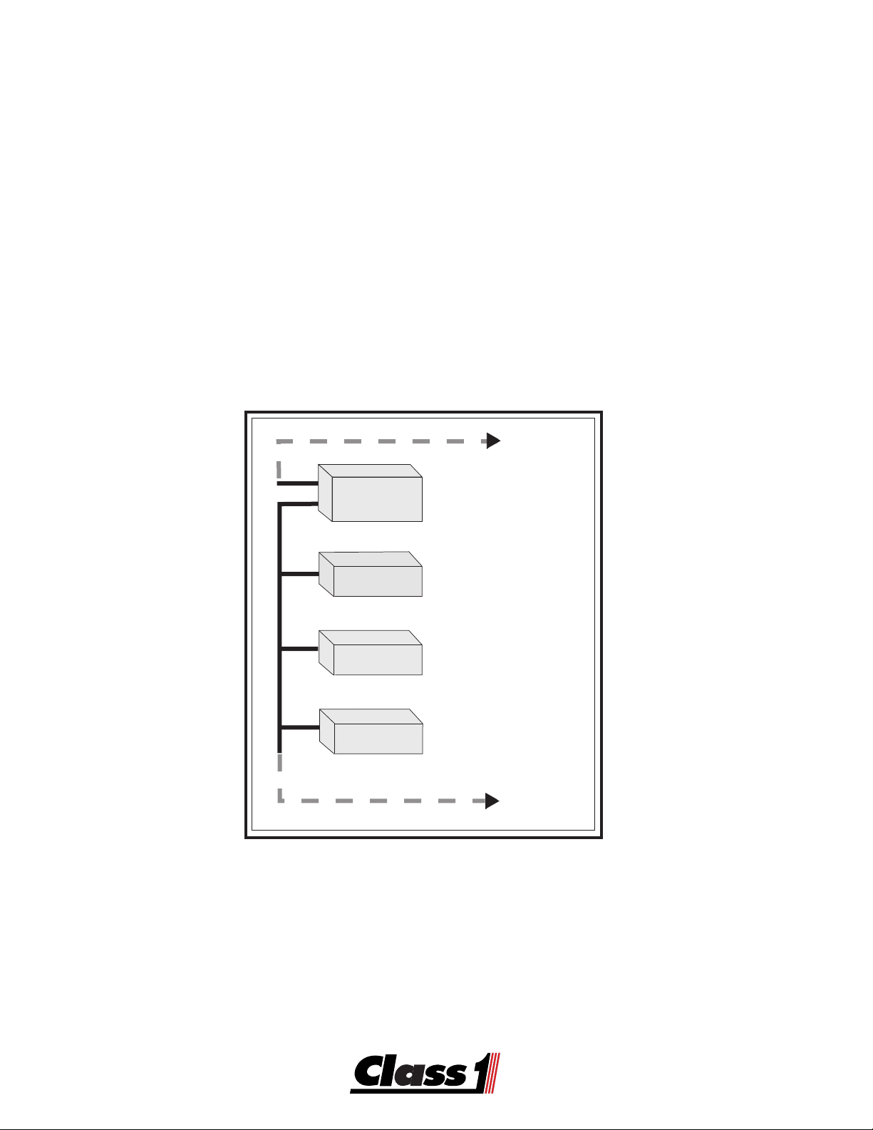
USM Network
TMTM
TM
The
Class1
ES-KES-K
ES-K
ES-KES-K
electrical system. The system is multiplexed using the Controller Area Network bus and the
SAE J-1939 protocol. An electrical database is used by the Control Module to operate the
vehicle electrical system. The
this database. Troubleshooting of the system is also accomplished with the software.
The Controller Area Network (CAN) has specific requirements that should be met for
maximum reliability.
TMTM
ee
y y
Sy Sy
stst
Sy
Sy Sy
em em
st
em
consists of several components that can be used in a vehicle
stst
em em
TMTM
TM
TMTM
ES-KES-K
ES-K
ES-KES-K
ee
y y
Expr Expr
eses
s s
e
y
Expr
ee
y y
Expr Expr
software allows you to create, read or modify
es
s
eses
s s
To other
J-1939 Devices
e
y
ee
y y
Control
Module
Switch
Module
Vocation
Module
Output
Module
Main Controller
and
User Interface
Interface to
Switch Panel
Vocation Interlock
Trans/Engine
Interface
Power Switching
to Loads
To other Devices
on the Management
Network Segment
Network modules communicate with each other through the J-1939 Controller Area Network.
2
Page 3
Network
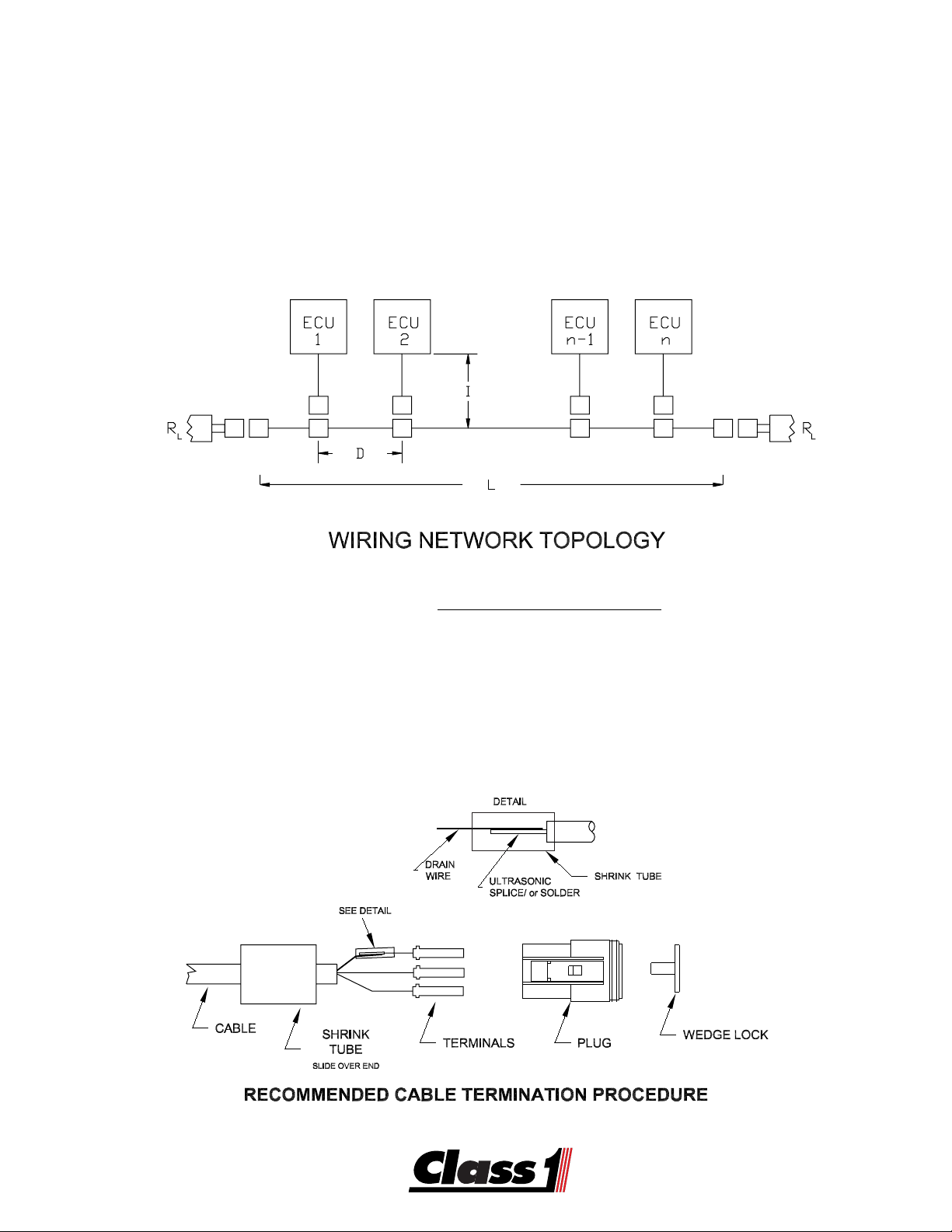
Wiring Network Topology
The wiring topology for this CAN based network should be as close as possible to a linear
structure in order to avoid cable reflections. In practice, it may be necessary to connect short
cable tails to a main backbone cable, as shown in the figure below. To minimize standing
waves, nodes should not be placed equally spaced on the network and cable tails should not
all be the same length.
Where: n= # modules in network/
L= Bus length
D= Node distance
I= Cable tail length
RL=Terminating resistor = 120Ω*
* Class 1 offers this resistor built into a harness connector DT06-3S-P006
30 maximum per network
• Recommended Cable Termination Procedure:
3
Page 4
Hardware
The ES-Key System utilizes a variety of modules to perform various functions. With the
exception of the USM Control Module, Display and Data Logger, there can be up to 16 of
each type module. They are addressed in the system by device type and number. For
instance, a Power Distribution Module can exist at address 0 through F (15) and a Switch
Input Module could be set at the same address since it is a different type. The address is set
on each module with either a Binary Coded Decimal (BCD 0-9) switch or a Hexadecimal
Encoded (Hex 0-F) switch.
Modules 10-15 are encoded as modules A-F respectively.
A=10, B=11, C=12, D=13, E=14 and F=15.
0
9
1
8
7
2
3
6
4
5
0
F
E
D
C
B
A
BCD HEX
PDM 8
ES-Key
Module
1
2
3
4
5
6
7
8
9
4
Page 5

Hardware
There are several modules available to perform various tasks in the system.
The Universal System Manager (USM) is the control module and performs load management, logic and main communications functions of the system. The USM contains the database for the system. Currently, there can be only one control module in a system.
A system can contain a Digital Display Module (Display). Four pages (4 lines by 20 characters) of greetings messages and 50 pages of extended messages can be stored in the display. In addition, live information about active and inactive circuits can be displayed and it
can be used as an interface to the system.
A Modem Module (MODEM) can be added to any circuit and will allow the system to be
accessed remotely by Express Software through a serial port or modem.
There can be up to 16 Power Distribution Modules (PDM) in a system. The PDM’s control the
loads in a circuit. They come in two basic types, electromechanical (relay boards) and electronic (solid state). They can handle from 7.5 amps up to 40 amps dependent on the exact
module specified. One of these modules is configured as an 8 input, 8 output, 4 motor driver
(H-bridge). A low current (250 mA) 16 Output Module is available for use in indicator or driver
circuits. The 16 output module comes in a variety of lowside and highside driver configurations. (Power or Ground outputs)
There can also be up to 16 Switch Input Modules (SIM) in a system. These come in either 16
positive input or 16 polarity selectable input versions. Any switch or input in the system needs
to be tied to an input circuit on a module in the system.
Vocation Modules are available for interlocking and engine control tasks. These are enginetransmission specific and there can only be one in a system.
A data logger is available that stores system fault and interlock information. It can aso be
configured to log specified circuit information. It will store 200 system faults and 6,000 events
before it loops around and overwrites the oldest data. These events are all dated and time
stamped to the nearest second. Up to 32 circuits can be tied to the data logger for troubleshooting or information purposes. It is also a true time clock and a temperature sensor can
be wired into it. The time is displayed on the data logger. The temperature and time are
displayed on the Display Module.
There are variations of some of the above modules available.
5
Page 6
Addresses
Every INPUT and every OUTPUT in the system has a unique address.
That address consists of a device type, a module number and a port on that device.
As an example, the first output on the first Power Distribution Module would be addressed as
PDM 0, Output 0.
In a typical system, it would be labelled for the load that is connected to it. If it were the Pump
Panel Lights connected to the first output, then a name (tag or label) indicating Pump Panel
Lights could be assigned to PDM 0, Output 0 and the operator would use the tag name
instead of PDM 0, Output 0 when referring to that circuit.
--SYSTEM OUTPUTS--
CIR:Pump Panel Lgts
ESC
POWER MOD#0 OUT-00
[MNGT] [MPLX] [INTK]
Each device type in the system that can have multiple devices has an address that is set by
either a hexadecimal (hex) or binary coded decimal (bcd) switch. Each module of the same
device type must have a unique address (0-F). A power distribution module (PDM) located in
the pump panel could be set to address 3 and would be accessed by the system as PDM 3.
Any output or input on that PDM would be known as PDM 3 and it’s port number and function
(Input/Output).
PDM module addresses are 0-F, Output Ports 0-11 and Input Ports 0-7.
SCROLL
--SYSTEM OUTPUTS--
CIR:Rear Scene Lgts
ESC
POWER MOD#3 OUT-07
[MNGT] [MPLX] [INTK]
SCROLL
As an example, an 8 input, 8 output relay board with its address switch at position 3 would
have input ports 0-7 and output ports 0-7.
The inputs would be PDM 3, Input 0 through Input 7 and the outputs would be PDM 3, output
0 through output 7.
Each of these inputs and outputs can be and usually are named for the circuit or function that
they are connected to.
Each circuit must have a unique name (limited to 16 characters) and be tied to a device type,
address and port.
--SYSTEM INPUTS--
CIR: Pump Lgt Switch
ESC
POWER MOD#0 IN-01
SCROLL
6
Page 7
Logic
SCROLL
ESC
Each output is operated by the logic associated with it in the database.
There are three types of logic for each circuit.
AND All the conditions associated with the circuit must be ON for the circuit to be ON.
OR Any of the conditions associated with the circuit can be ON for the circuit to be ON.
NOT The associated condition must be OFF or false for the circuit to turn ON.
MUX: circuit name
1: Condition 1 LOGIC
ESC
2: Condition 2
[GO->1] [BACK] [GO->2]
SCROLL
MUX :Pump Panel LTS
1 :Pump LT Switch
[GO->1] [BACK]
Further there are three logic conditions that apply to every output.
Multiplex Logic ties an output to two conditions, these can be AND’ed, OR’ed or Inverted
(NOT). The default condition is false or OFF. The conditions can be inputs or
outputs
MUX: Work Lights
1: Work LT Switch OR
ESC
2: Marker LT Switch
SCROLL
[GO->1] [BACK] [GO->2]
Load Management Logic allows each output circuit to be sequenced on, shed (turned off
below a specific priority or voltage level), tied to either of two operational modes (A or B) and
be staged (controlled by a discrete input). The default condition is true or ON.
MNG: circuit name
SEQUENCE:1 SHED:0
ESC
MODE:A or B; STAGE:N
SCROLL
[BACK] [HELP]
Vocation Logic is available when a vocation module is installed. Each output can be tied to
any or all of several interlocks. The output can also be controlled by a NOT interlock, the
circuit will only be operated if the interlock is OFF.
The default condition for vocation logic is true (no connection).
INTERLOCKS: [SCROLL]
CIR:Pump Panel LTS
ESC
INTERLOCK
: -X-
SCROLL
[BACK] [NEXT]
All three of the above logic conditions apply to every output and they are ANDed together.
They all must be true for a circuit to operate.
7
Page 8

Example
Example 1:
Pump Panel Lights Assigned to PDM 3 Output 0
Pump Panel Switch Assigned to PDM 3 Input 0
Marker Light Switch Assigned to SIM 0 Input 0
The Pump Panel Lights are set to come on with the Pump Panel Switch or the Marker Light
Switch.
Multiplex
ON whenever the Pump Panel Switch is ON OR the Marker Light Switch is ON.
Logic
Management
Vocation
Whenever the Marker Light Switch or the Pump Panel Switch is turned on, the Pump
Panel Lights will turn ON.
Example 2:
The Pump Panel Lights are set to come on with the Pump Panel Switch OR the Marker Light
Switch AND in Scene Mode.
Multiplex
ON whenever the Pump Panel Switch is ON OR the Marker Light Switch is ON.
Management
Vocation
Whenever the Marker Light Switch or the Pump Panel Switch is turned on, the Pump
Panel Lights will turn ON
Logic
Logic
Logic
Logic
Logic
defaults to true.
defaults to true.
AND
set to mode B (Scene Mode).
AND
defaults to true.
as long as the Park Brake is set
.
Example 3:
The Pump Panel Lights are set to come on with the Pump Panel Switch OR the Marker Light
Switch AND in Scene Mode if it is Okay to Pump.
Multiplex
ON whenever the Pump Panel Switch is ON OR the Marker Light Switch is ON.
Management
Vocation
Whenever the Marker Light Switch or the Pump Panel Switch is turned on, the Pump
Panel Lights will turn ON
transmission is in high range lockup.
8
Logic
Logic
Logic
AND
set to mode B (Scene Mode).
AND
set to Okay to Pump.
as long as the Park Brake is set
AND the pump is engaged and the
Page 9
Example
--SYSTEM OUTPUTS--
CIR:Pump Panel Lgts
ESC
POWER MOD#3 OUT-00
[MNGT] [MPLX] [INTK]
--SYSTEM INPUTS--
CIR: Marker Lgt Switch
ESC
INPUT MOD#0 IN-00
--SYSTEM INPUTS--
CIR:Pump Panel Switch
ESC
POWER MOD#3 IN-00
SCROLL
SCROLL
SCROLL
--SYSTEM OUTPUTS--
CIR:Pump Panel Lgts
ESC
POWER MOD#3 OUT-00
[MNGT] [MPLX] [INTK]
SCROLL
MUX: Pump Panel Lgts•
1: Markew LT Switch OR
ESC
2: Pump Panel Switch
[GO->1] [BACK] [GO->2]
MUX :Pump Panel LTS
1 :Pump LT Switch
ESC
[GO->1] [BACK]
MUX: Work Lights
1: Work LT Switch OR
ESC
2: Marker LT Switch
[GO->1] [BACK] [GO->2]
SCROLL
SCROLL
SCROLL
9
Page 10

Power Modules
The ES-Key System uses Power Distribution Modules (PDM’s) to supply current to electrical
loads. Currently these are available in two basic styles and there can be up to 16 of them in
the system.
Relay Modules use standard 30/40 Amp automotive relays and are available in 8 and 12 relay
configurations. Both relay boards have two relays that the common terminal can be set to
discrete inputs. The power to the board must be OFF any time that the switch for these
outputs is changed. The rest are common bussed to system voltage. Both boards have eight
inputs, 4 of which are polarity selectable and the other 4 are ground inputs. Each output has
a feedback circuit to identify to the system it’s current status (OFF or ON). If an output is
supposed to be on, but has no feedback, a fault is generated that can be easily traced.
Whenever a PDM is installed or replaced, it is essential that the address switch be positioned
correctly for it’s function in the system. Each load is turned on by device type, address and
port. Relay #1 on relay board #1 would be addressed as PDM #1, Port #1 and most likely be
named for the load that is connected to it. Any PDM whose address switch is at number 1 will
respond to a turn on or off command unless there is an address conflict.
Connector Information
Amp Mini Universal Mate-N-Lok
Power Amp 172165-1 1) Power 2) Ground
CAN Amp 172166-1 1) Can HI 2) CAN LO 3) CAN Shield
Input Amp 770579-1 1) Input 0 select 5) Input 4 ground
2) Input 1 select 6) Input 5 ground
3) Input 2 select 7) Input 6 ground
4) Input 3 select 8) Input 7 ground
Amp Socket Terminals
Tin 101535
Gold 103374
10
4 3 2 1
8 7 6 5
Page 11

Power Modules
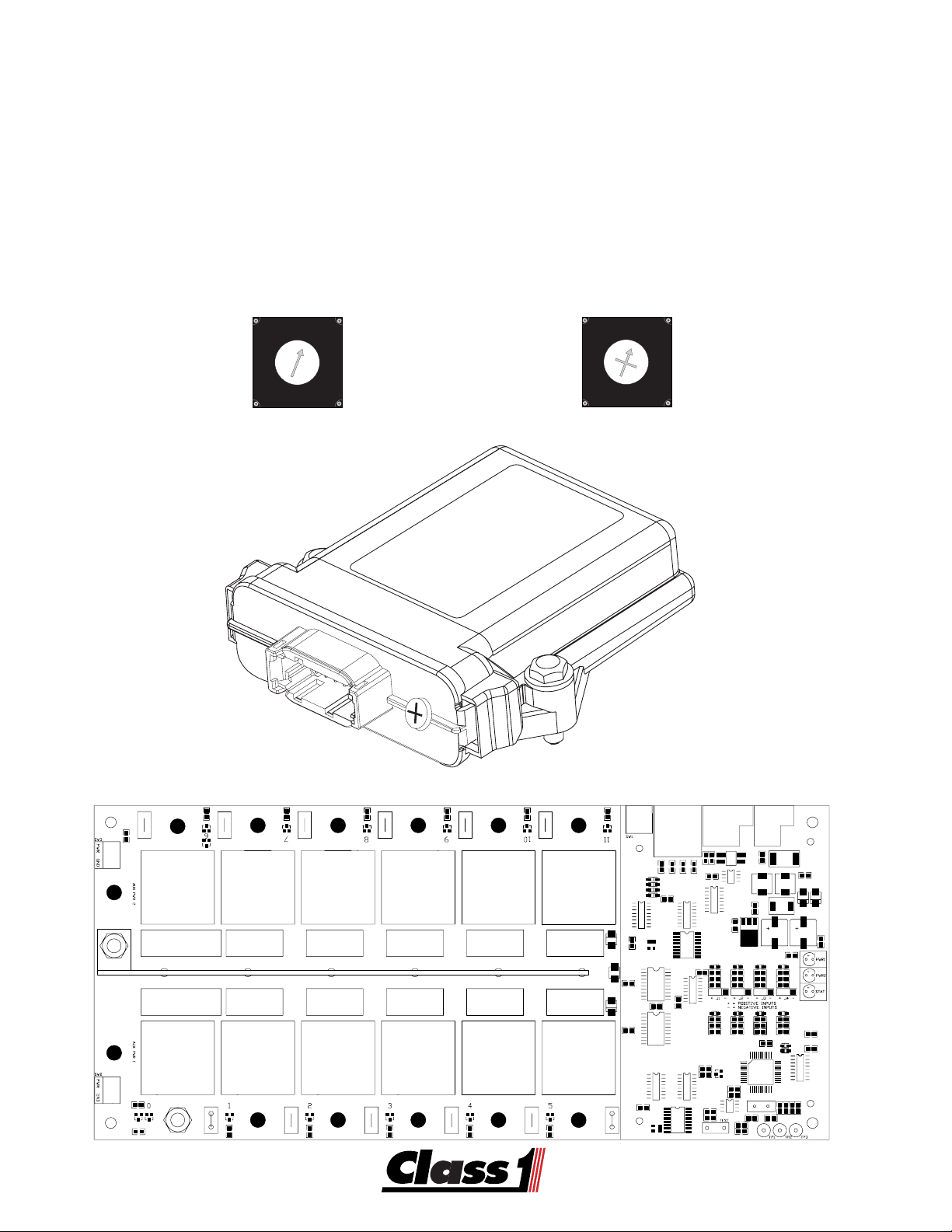
Solid State Modules use an integrated circuit driver to supply current to its loads. Outputs are
common bussed to system power and can deliver up to 7.5 Amps. Current levels above two
(2) amps can be used to indicate whether an output is ON or OFF. These modules use a Hex
switch for addressing and come in three (3) styles.
104434 Eight (8) output PDM-8
104528 Six output Two input PDM-(6/2)
104529 Four output Four input PDM-(4/4)
Solid State Modules with inputs have polarity selectable inputs.
Any output can be made to flash, the first four inputs flash at one instance and the second
four flash at the opposite instance (anti-flash).
The flash rate can be configured to 75 FPM or 150 FPM.
Connector Information
DTM06-12SA Lock WM-12S
Deutsch 20 Ga Sockets
1062-20-0122 for 16-10 Ga wire
0462-201-20141 for 18-24 Ga wire
0462-201-2031 Gold Contacts 18-24 Ga wire
PWR
BUS
COM
7 8 9 10 11 12
6 5 4 3 2 1
Eight Output Six OUT/Two IN Four OUT/Four IN
1 Output 0 1 Output 0 1 Output 0
2 CAN HI 2 CAN HI 2 CAN HI
3 CAN Shield 3 CAN Shield 3 CAN Shield
4 Output 2 4 Output 2 4 Output 2
5 Output 4 5 Output 4 5 Input 3
6 Output 6 6 Input 1 6 Input 1
7 Output 7 7 Input 0 7 Input 0
8 Output 5 8 Output 5 8 Input 2
9 Output 3 9 Output 3 9 Output 3
10 Output 1 10 Output 1 10 Output 1
11 CAN LO 11 CAN LO 11 CAN LO
12 Ground 12 Ground 12 Ground
Power Stud 10-32 thread/#10 Ring
11
Page 12

Motor Control
The ES-Key Motor Control Module (PDM) is a solid state module capable of providing up to
15 Amps per output. It has 8 polarity selectable inputs, 8 positive outputs and 4 motor control
circuits (H-bridge).
Connector Information
Power, Ground CAN DT06-6SA Lock W-6S
Inputs DT06-8SA Lock W-8S
Outputs DT06-8SB Lock W-8S
Motors DT06-8SC Lock W-8S
Deutsch 16 Ga Sockets
1062-20-0122 for 16-10 Ga wire
Output (Black) Input (Grey) Motor Control (Green) PWR,GND,CAN (Grey)
1 Output 0 1 Input 0 1 Motor 1 1 12 VDC
2 Output 1 2 Input 1 2 Motor 2 2 Ground
3 Output 2 3 Input 2 3 Motor 3 3 NC
4 Output 3 4 Input 3 4 Motor 4 4 CAN HI
5 Output 4 5 Input 4 5 Motor 4 5 CAN LO
6 Output 5 6 Input 5 6 Motor 3 6 CAN shield
7 Output 6 7 Input 6 7 Motor 2
8 Output 7 8 Input 7 8 Motor 1
12
Page 13

Solid State PDM
Solid State Modules use an integrated circuit driver to supply current to it’s loads. Outputs
are common bussed to system power and can deliver up to 7.5 Amps. Current levels above
two (2) amps can be used to indicate whether an output is ON or OFF. These modules use a
Hex switch for addressing and come in three (3) styles.
104434 Eight (8) output PDM-8
104528 Six output Two input PDM-(6/2)
104529 Four output Four input PDM-(4/4)
Solid State Modules with inputs have polarity selectable inputs.
Any output can be made to flash, the first four inputs flash at one instance and the second
four flash at the opposite instance (anti-flash).
The flash rate can be configured to 75 FPM or 150 FPM.
PWR
BUS
COM
7 8 9 10 11 12
6 5 4 3 2 1
The PWR LED indicates whether the system electronics have power or not.
The BUS LED indicates whether or not there is power for the output loads.
The green LED is on steady with good communications.
A slow flash rate indicates that communications are down.
A fast flash rate means that there is an address conflict with another module.
If the LED is off, communications to and from the module are noit present.
13
Page 14

Switch Modules
The ES-Key System uses Switch Input Modules (SIM’s) to provide switching information to
the system. Currently these are available in two basic styles and there can be up to 16 of
them in the system.
16 Positive (103372) Switch Input Module
Connector Information
Amp Mini Universal Mate-N-Lok
Power Amp 172165-1 1) Power 2) Ground
CAN Amp 172166-1 1) Can HI 2) CAN LO 3) CAN Shield
Input Amp 770579-1 1) Input 0 positive 9) Input 8 positive
2) Input 1 positive 10) Input 9 positive
3) Input 2 positive 11) Input 10 positive
4) Input 3 positive 12) Input 11 positive
5) Input 4 positive 13) Input 12 positive
6) Input 5 positive 14) Input 13 positive
7) Input 6 positive 15) Input 14 positive
8) Input 7 positive 16) Input 15 positive
Amp Socket Terminals
Tin 101535
Gold 103374
0
9
1
8
2
7
3
6
4
5
14
8 7 6 5 4 3 2 1
16 15 14 13 12 11 10 9
Wire Side
Page 15

Switch Modules
6 5 4 3 2 1
Phone 352 629 5020
Fax 352 629 2902
http://www.class1.com
607 NW 27th Ave
Ocala, FL 34475
IN 14
IN 12
CAN S
CAN H
PWR
PN 104409
IN 15
IN 13
CAN L
GND
7 8 9 10 1112
Switch Input Modules have 16 available inputs which are individually polarity selectable.
These modules use a Hex switch for addressing and come in three (3) styles.
104508 Sixteen (16) Input SIM-16
104462 Sixteen Input Three Output SIM-16/3
10xxxx Sixteen Input/ One OUT/2 Analog SIM-16/1/2
All inputs are polarity selectable using DIP switches on the circuit card.
Connector Information
DTM06-12SA Lock WM-12S DTM06-12SB Lock WM-12S
Deutsch 20 Ga Sockets
1062-20-0122 for 16-10 Ga wire
0462-201-20141 for 18-24 Ga wire
0462-201-2031 Gold Contacts 18-24 Ga wire
DIGITAL INPUT
IN 5
IN 11
IN 9
IN 3
IN 1
IN 7
CAN L
GND
IN 15
IN 13
1 2 3 4 5 6
7 8 9 10 1112
12 1110 9 8 7
6 5 4 3 2 1
IN 12
IN 14
PWR
CAN S
CAN H
IN 6
IN 4
IN 2
IN 0
IN 10
IN 8
Phone 352 629 5020
607 NW 27th Ave
Fax 352 629 2902
Ocala, FL 34475
http://www.class1.com
PN 104409
DTM06-12SA DTM06-12SB
1 Power 1 INPUT 11
2 CAN HI 2 INPUT 9
3 CAN Shield 3 INPUT 7
4 (OUT 2) 4 INPUT 5
5 INPUT 12 5 INPUT 3
6 INPUT 14 6 INPUT 1
7 INPUT 15 7 INPUT 0
8 INPUT 13 8 INPUT 2
9 (OUT 0) 9 INPUT 4
10 (OUT 1) 10 INPUT 6
11 CAN LO 11 INPUT 8
12 Ground 12 INPUT 10
15
Page 16

USM 103383
USM Control Module (PN 103383)
TMTM
TM
The USM Control Module is the primary module in the system. It has an
ES-KES-K
ES-K
ES-KES-K
to transfer information to and from the microprocessor memory as well as the capability to
interface with a computer on the CAN bus. Direct access can be made through five switches
and a twenty character by four line display on the USM. These are used to access the menu
driven information, programming and diagnostic features. All logic and control for the system
is handled by the USM Control Module. The menu is the user interface to the system allowing
one to view information about the system, diagnose it and program load management functions.
Class1, Inc.
TMTM
TM
TMTM
ee
y y
Sy Sy
Sy
Sy Sy
stst
st
stst
e
y
ee
y y
VV
ersion 2.02dersion 2.02d
V
ersion 2.02d
VV
ersion 2.02dersion 2.02d
emem
em
emem
SCROLL
ESC
ES-KES-K
ES-K
ES-KES-K
[MENU]
TMTM
ee
y y
C C
arar
y
y y
C
C C
ar
arar
d d
d
reader
d d
e
ee
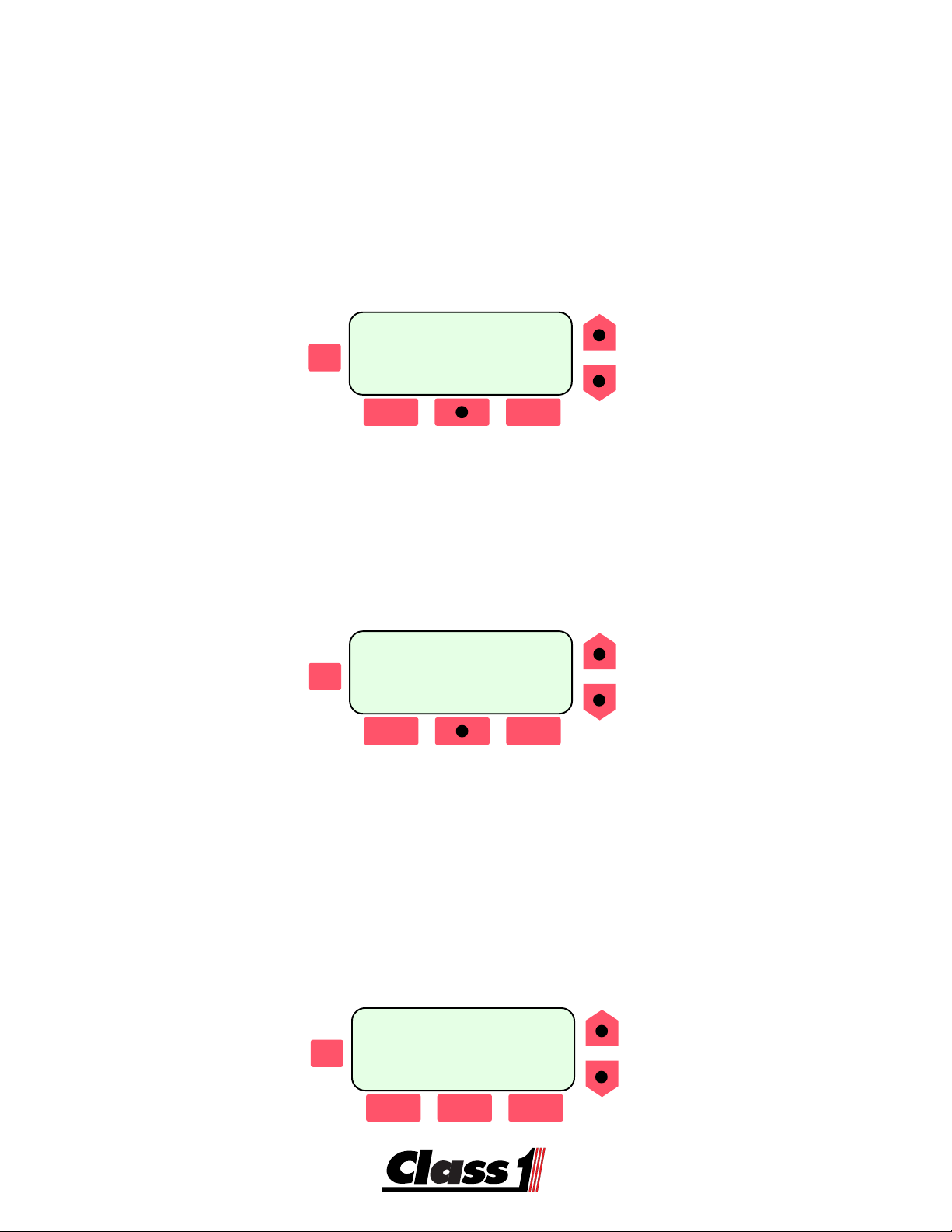
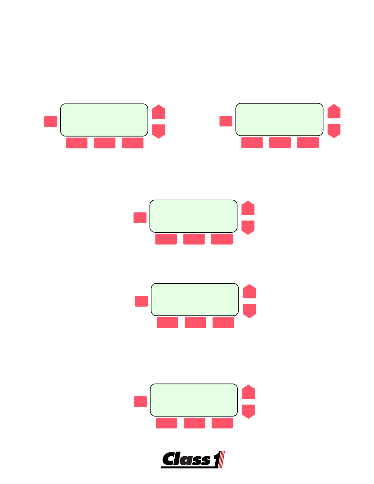
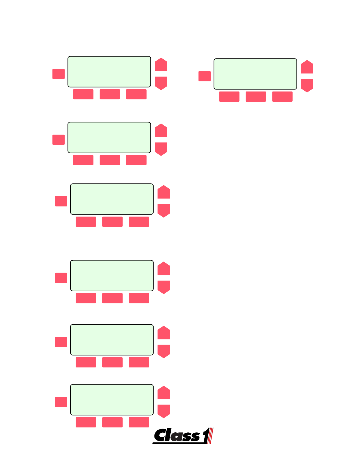
In normal operation, the center switch is active with [menu] being displayed just above it.
The escape [ESC] switch is always active when in the menu system and will move up one
level each time that it is pressed until the top level is reached.
The [SCROLL] switches are active in certain menus to locate input or output data from a list.
The three switches just below the display window are used to control the menu system. They
become active and their function identified by text immediately above the switch. No text
above a switch indicates that it has no function in that menu.
TMTM
TM
Press the red switch directly under [MENU] to enter the
ES-KES-K
ES-K
ES-KES-K
TMTM
ee
y y
Sy Sy
stst
Sy
Sy Sy
st
stst
emem
em
menu.
emem
e
y
ee
y y
In this section, a pressed switch is indicated by a black dot on the switch.
16
Page 17

System Logic
The ES-Key System utilizes an electrical connection database for operation. This database
is written by the OEM and contains all the information necessary to operate the ES-Key
System for a specific vehicle. The system can be customized to the user’s needs without
changing the physical wiring or hardware. This database can be ‘read’ by the user and is an
‘as built’ wiring diagram that stays with the system.
Each ‘output circuit’ has three conditions of operation:
Multiplexing:
Two conditions of operation are available for each circuit.
These conditions can be logically ‘AND’ed (both conditions must be true) or
logically ‘OR’ed (either condition can be true) to each other.
Additionally, either or both of these conditions can use ‘NOT’ logic.
‘NOT’ logic simply means that the condition must be false for the system to
consider it true.
The conditions can be inputs or outputs from anywhere in the system.
--SYSTEM OUTPUTS--
CIR:Pump Panel Lgts
ESC
POWER MOD#0 OUT-01
[MNGT] [MPLX] [INTK]
Load Management:
Outputs can be load managed to sequence on and sequence off.
Outputs can be load managed to shed at a specific voltage level.
Outputs can be managed to operate in Mode A, Mode B or both.
Outputs can be tied to a Staged input.
System Outputs
CIR: PDM0 RLY 0
ESC
POWER MOD#0 OUT 0
[MNGT] [MPLX] [INTK]
MUX:circuit name
SCROLL
1:Condition 1 LOGIC
ESC
2:Condition 2
SCROLL
[GO->1] [BACK] [GO->2]
Fire Service Mode A is typically Response and Mode B is Scene.
Staging for the fire service is typically the Warning Master Switch.
MNG:PDM0 RLY 0
SCROLL
SEQUENCE:0 SHED:0
ESC
MODE B ONLY;STAGE:Y
[BACK] [HELP] [EDIT]
SCROLL
Interlocking:
System Outputs
CIR: PDM0 RLY 0
ESC
POWER MOD#0 OUT 0
[MNGT] [MPLX] [INTK]
Any output can be tied to any of several interlocks available from an ES-Key
Vocation Module.
INTERLOCKS [SCROLL]
SCROLL
CIR:Circuit Name
ESC
Pump Shift : ON
[BACK] [NEXT]
SCROLL
17
Page 18

MNGT Data
ES-KEY USER MENU
SELECT OPTION
ESC
[UTIL] [DATA]
Selecting=xa^q^z=presents the system database for review.
SCROLL
ESC
-- SYSTEM OUTPUTS --
CIRCUIT NAME
CIR:
MODULE
TYPE ADDRPORT
SCROLL
ESC
-- SYSTEM INPUTS --
CIRCUIT NAME
CIR:
MODULE
TYPE ADDR PORT
SCROLL
[MNGT] [MPLX] [INTK]
The scroll arrows allow you to see all of the system inputs and outputs.
The top line of the display indicates whether the circuit is an INPUT or OUTPUT.
The second line shows the Circuit Name.
The third line gives the module type, it’s address 0-15 and the port on the device that the
circuit is assigned to.
The fourth line is only active for OUTPUTS and allows the user to select one of three submenus for more information on the circuit.
[MNGT] provides a menu detailing the circuits load management information.
[MPLX] provides a menu detailing the circuits multiplexing information.
[INTK] provides a menu detailing the circuits interlock information.
-- SYSTEM OUTPUTS --
CIR: LIGHT BAR
ESC
POWER MOD#0 OUT-01
[MNGT] [MPLX] [INTK]
SCROLL
This screen indicates that the circuit ‘LIGHT
BAR’ is an output located on a Power Module addressed as zero (0) and physically is
on port one (1) of that module.
MNG:PDM 0 1
SEQUENCE:3 SHED:0
ESC
MODE:A OR B; STAGE Y
[BACK] [HELP]
-- DEFINED BY OEM --
MODE A : RESPONSE
ESC
MODE B : SCENE
STAGE : MASTER WARN
MNG:PDM 0 1
SEQUENCE:3 SHED:0
ESC
MODE:A OR B; STAGE Y
[BACK] [HELP]
18
SCROLL
SCROLL
SCROLL
The Management screen shows that this
output sequences on third, never sheds, will
be on in either scene (mode a) or response
mode (mode B) and is tied to the Master
Warning Switch (staged).
The HELP screen displays the OEM’s defi-
nition of Mode A and B as well as what the
Staged input is.
Press any key to return to the Management
Screen.
Pressing the BACK Switch returns you to the
‘Circuits Menu’
Page 19

MPLX Data
-- SYSTEM OUTPUTS --
CIR: LIGHT BAR
ESC
POWER MOD#0 OUT-01
[MNGT] [MPLX] [INTK]
Selecting [MPLX] brings up the system multiplex menu.
SCROLL
MUX: LIGHT BAR
1: Switch LIGHT BAR
ESC
[GO-1] [BACK]
MUX: LIGHT BAR
1: Switch LIGHT BAR
ESC
[GO-1] [BACK]
-- SYSTEM INPUTS --
CIR:Switch LIGHT BAR
ESC
POWER MOD#0 INP-01
SCROLL
SCROLL
SCROLL
The multiplex information screen shows the
arguments that must be true for the circuit to
operate. The scroll switches select different
circuits. [BACK] returns you to the Circuits
Menu.
Pressing the [GO-1] switch takes you to the
circuit menu for that argument.
The circuit screen shows that condition 1 is
the LIGHT BAR Switch and it is located on
the power distribution module at address 0
and input #1 on that module. Scroll to the
next circuit or escape to a higher level menu.
MUX: INNER LIGHT BAR
1: First Switch OR
ESC
2: Second Switch
[GO-1] [BACK] [GO-2]
Pressing the BACK Switch returns you to the ‘Circuits Menu’
-- SYSTEM OUTPUTS --
CIR: INNER LIGHT BAR
ESC
POWER MOD#0 OUT-02
[MNGT] [MPLX] [INTK]
SCROLL
SCROLL
If there are two arguments used, both of them
will show on the MPLX screen and either the
GO-1 or GO-2 switch can be accessed for
information on the arguments.
19
Page 20

INTK Data
-- SYSTEM OUTPUTS --
CIR: LIGHT BAR
ESC
POWER MOD#0 OUT-01
[MNGT] [MPLX] [INTK]
Selecting [INTK] brings up the system multiplex menu.
SCROLL
INTERLOCKS [SCROLL]
CIR: LIGHT BAR
ESC
PARK BRAKE :OFF
[BACK] [NEXT]
INTERLOCKS [SCROLL]
CIR: LIGHT BAR
ESC
PARK BRAKE :OFF
[BACK] [NEXT]
INTERLOCKS [SCROLL]
CIR: LIGHT BAR
ESC
PUMP ENGAGED :ON
[BACK] [NEXT]
SCROLL
SCROLL
SCROLL
The interlock information screen shows the
circuit name and allows you to view each of
the interlocks and how it is related to the circuit.
Either -X-, the interlock is not associated with
the circuit or OFF or ON indicates whether
the interlock must be on or off for the circuit
to turn on.
This indicates that the Park Brake must be
OFF for the LIGHT BAR to work.
Pressing the [NEXT] switch takes you to the
next interlock. Pressing the UP or DOWN
arrow selects the next circuit to view in the
interlock sub-menu.
This indicates that the pump must be engaged for the LIGHT BAR to work.
INTERLOCKS [SCROLL]
CIR: LIGHT BAR
ESC
PUMP ENGAGED :-X-
[BACK] [NEXT]
INTERLOCKS [SCROLL]
1: Switch LIGHT BAR
ESC
PARK BRAKE :OFF
[BACK] [NEXT]
Pressing the BACK Switch returns you to the ‘Circuits Menu’
20
SCROLL
SCROLL
This indicates that the circuit LIGHT BAR
doesn’t care if the Pump is engaged or not.
Pressing [BACK] selects the Circuits Menu.
Page 21

Enter the menu system by pressing the switch immediately below [MENU].
ES-KEY USER MENU
SELECT OPTION
ESC
[UTIL] [DATA]
ES-KEY Utilities
ESC
[DIAG] [CARD]
Fault Menu
Class1, Inc.
ES-KEY SYSTEM
ESC
SCROLL
SCROLL
Version 2.02d
[MENU]
SCROLL
The two main sub-menu sections are utilities and data.
Select [UTIL]
Under the utilities menu are three areas that
can be accessed:
diagnostics, data logger (if it exists in
the system) and card.
Select [DIAG]
ES-KEY DIAGNOSTICS
ESC
[OTHER] [FAULTS]
-SYSTEM FAULT CODES-
ESC
CURRENT/ACTIVE: 3
HISTORICAL LOG: 5
ES-KEY DIAGNOSTICS
ESC
[OTHER] [FAULTS]
SCROLL
SCROLL
SCROLL
Under ES-Key Diagnostics, a [FAULTS]
Menu and an [OTHER] Menu is available.
Select [FAULTS]
Displayed will be the number of current faults
and the number of historical faults.
Pressing ESC returns you to the ES-Key Diagnostics selection menu.
Selecting [OTHER] will take you to the Information on card, network or system selection
menu.
Pressing [ESC] returns you to the Select [ES-Key DIAGNOSTICS] menu
21
Page 22

Module Menu
Information on card,
fеСзкг~нбзе=çå=Å~êÇIfеСзкг~нбзе=çå=Å~êÇI
fеСзкг~нбзе=çå=Å~êÇI
fеСзкг~нбзе=çå=Å~êÇIfеСзкг~нбзе=çå=Å~êÇI
network or system?
еЙнпзкв=çê= лулнЙг\еЙнпзкв=çê= лулнЙг\
еЙнпзкв=çê= лулнЙг\
ESC
еЙнпзкв=çê= лулнЙг\еЙнпзкв=çê= лулнЙг\
[NET] [SYS] [CARD]
=x=x
kbqkbq
=x
=x=x
z==xpvpz==x`^oazz==xpvpz==x`^oaz
kbq
z==xpvpz==x`^oaz
kbqkbq
z==xpvpz==x`^oazz==xpvpz==x`^oaz
Select Network I/O,
Modules, or Vocation
ESC
[MOD] [I/O] [VOC]
MOD:POWER ADDR:00
STATUS: LOCATED
ESC
v1.01 PDM 8-Relay
Msg/sec:Tx=XX Rx=XX
SCROLL
SCROLL
SCROLL
The [NET] menu opens a selection window
for information on the network modules, inputs, outputs or the vocation module.
Pressing [MOD] allows individual modules
to be queried and module information to be
displayed.
The display will indicate the Device Type, it’s
address, communications status, software
version, module type and the number of messages per second sent and received.
Scroll through all the modules in the database to verify that they are on-line.
MOD:DISPLAY ADDR:00
STATUS: LOCATED
ESC
v1.03 Display 1
Msg/sec:Tx=XX Rx=XX
SCROLL
=MOD:DATA LOGGER
STATUS: LOCATED
ESC
v1.01 Data Logger
Developer’s Module
SCROLL
=MOD:VOCATION/INTLK
STATUS: LOCATED
v1.01 PTO/Drive Gear
Developer’s Module
ESC
NOTE 1: THE CONTROL MODULE WILL ONLY LOOK FOR DEVICES THAT ARE CONTAINED IN THE ACTIVE DATABASE.
SCROLL
ANY MODULE WITH A STATUS: NOT LOCATED SHOULD BE INVESTIGATED.
IF AN UNKNOWN MODULE APPEARS, THE DATABASE IS MORE THAN LIKELY CORRUPT.
MOD:INPUT ADDR:00
STATUS: NOT LOCATED
ESC
SCROLL
Pressing [ESC] will display the Select Network I/O, Modules or Vocation Select Menu.
Locating all the modules in the system can let you know if there are any communications
problems and where they might be located.
22
Page 23

I/O-VOC Menu
Select Network I/O,
Modules, or Vocation
ESC
[MOD] [I/O] [VOC]
CIR:LIGHT BAR
OUTPUT: OFF
ESC
CIR:LIGHT BAR SWITCH
INPUT: ON
ESC
SCROLL
SCROLL
SCROLL
Selecting [I/O] brings up the input and out-
put circuits page.
Each circuit on the vehicle can be looked
at by using the up and down arrows to
scroll through the circuits.
The screen will show whether the circuit
is an INPUT or an OUTPUT and whether
it is ON or OFF.
Pressing [ESC] returns you to the Select
Network I/O, Modules or Vocation menu.
Selecting [VOC] brings up the Interlock Sta-
tus Screen.
ESC
Select Network I/O,
Modules, or Vocation
SCROLL
[MOD] [I/O] [VOC]
CIR:PARK BRAKE
INTERLOCK STATE: OFF
ESC
[BACK] [NEXT]
SCROLL
Each of the interlocks on the vocation
module can be scrolled to using the
[NEXT] switch. It’s state will be shown as
either ON or OFF.
=CIR:OKAY TO PUMP
INTERLOCK STATE: ON
ESC
SCROLL
[BACK] [NEXT]
Pressing the [BACK] or the [ESC] switch brings you back to the Select Menu.
Select Network I/O,
Modules, or Vocation
ESC
[MOD] [I/O] [VOC]
SCROLL
23
Page 24

Information on card,
fеСзкг~нбзе=çå=Å~êÇIfеСзкг~нбзе=çå=Å~êÇI
fеСзкг~нбзе=çå=Å~êÇI
fеСзкг~нбзе=çå=Å~êÇIfеСзкг~нбзе=çå=Å~êÇI
network or system?
еЙнпзкв=çê= лулнЙг\еЙнпзкв=çê= лулнЙг\
еЙнпзкв=çê= лулнЙг\
ESC
еЙнпзкв=çê= лулнЙг\еЙнпзкв=çê= лулнЙг\
[NET] [SYS]
=x=x
kbqkbq
=x
=x=x
z==xpvpz==x`^oazz==xpvpz==x`^oaz
kbq
z==xpvpz==x`^oaz
kbqkbq
z==xpvpz==x`^oazz==xpvpz==x`^oaz
[CARD]
ENG Menu
SCROLL
The [SYS] menu opens a selection window
for information on Load Management, Engine or the database file.
Information on load man-
agement, Engine, or data-
ESC
base file?
[ENG] [MNGT] [FILE]
THROTTLE INPUT 000%
OUTPUT:0.0V PWM:00%
ESC
FIDLE:00% REMOTE:00%
[HSET] [IDLE] [EXIT]
CHANGE HIGH IDLE
SET-POINT TO 00% ?
ESC
[YES] [NO]
SCROLL
SCROLL
SCROLL
Pressing [ENG] brings up the Engine Fast
Idle and Throttle Menu. This menu is used
in conjunction with a Vocation Module. The
engine will be controlled if the proper interlocks are present.
THROTTLE INPUT: displays the panel
throttle position. OUTPUT: displays the analog engine control signal voltage. PWM: indicates the PWM engine control signal.
FIDLE: displays the percentage of full throttle
that a high idle signal will command. REMOTE: is the Throttle percentage commanded by the UP and DOWN switches.
With the proper interlocks, the engine can
be operated to a desired RPM. Once this
is accomplished, pressing [HSET] brings
up the menu to set the current RPM as
the HIGH IDLE RPM.
THROTTLE INPUT 000%
OUTPUT:0.0V PWM:00%
ESC
FIDLE:00% REMOTE:00%
[HSET] [IDLE] [EXIT]
SCROLL
Pressing YES or NO returns you to the
Engine Menu. IDLE brings the engine to
curb idle and EXIT returns you to the System Select Menu.
Information on load man-
agement, Engine, or data-
ESC
base file?
SCROLL
[ENG] [MNGT] [FILE]
Pressing Management [MNGT] brings you to the Load Management Display Screen.
24
Page 25

Information on load man-
agement, Engine, or data-
ESC
base file?
[ENG] [MNGT] [FILE]
LOAD MNGT: DISABLED
SEQ:4 SHED:7 STG:OFF
ESC
MODE A :Response
VOLTS: 13.8
LOAD MNGT: ENABLED
SEQ:4 SHED:7 STG:ON
ESC
MODE B :Scene
VOLTS: 13.8
MNGT Menu
SCROLL
SCROLL
SCROLL
The [SYS] menu opens a selection window
for information on Load Management, Engine or the database file.
Pressing [MNGT] brings up the Load Management View. The system Load Management data is presented. The sequence level,
shed level and system voltage are displayed.
The stage and mode conditions are shown
as well as whether load management is enabled or disabled.
LOAD MNGT: ENABLED
SEQ:4 SHED:7 STG:ON
ESC
MODE B :Scene
FORCE VOLTS: 13.8
LOAD MNGT: ENABLED
SEQ:4 SHED:4 STG:ON
ESC
MODE B :Scene
FORCE VOLTS:12.4 HOL
SCROLL
SCROLL
Information on load man-
agement, Engine, or data-
ESC
base file?
[ENG] [MNGT] [FILE]
Using the UP and DOWN arrows results
in a diagnostic mode where the voltage
display is changed by 0.1 VDC per switch
press. The system will act as if this were
the actual system voltage. Range is 10.0
VDC to 13.8 VDC.
There are three Letters that can appear
in the Bottom Right of the display.
H indicates that a High Idle output is active.
O means that a High Idle Override input
is active.
L indicates that the system Low Voltage
Alarm is active. to the System Select
Menu.
SCROLL
Pressing [ESC] returns you to the System Select Menu.
25
Page 26

FILE Menu
Information on load man-
agement, Engine, or data-
ESC
base file?
[ENG] [MNGT] [FILE]
--ACTIVE CARD FILE--
ESC
FILE: Electrical Spec
CREATED ON:04-15-00
Information on load man-
agement, Engine, or data-
ESC
base file?
[ENG] [MNGT] [FILE]
Information on card, net-
work or system?
ESC
[NET] [SYS] [CARD]
SCROLL
SCROLL
SCROLL
SCROLL
The [SYS] menu opens a selection window
for information on Load Management, Engine or the database file.
Pressing [FILE] brings up a display that
shows the file name and the date it was created.
Pressing any key returns you to the System Selection Menu.
Pressing ESC to return to the Card, Network or System selection menu.
- ES-KEY CARD DATA -
ESC
CARD: card title
CREATED ON: 03-21-99
Press ESC to return to the Card, Network or System selection menu.
Pressing [ESC] returns you to the ES-Key Diagnostics Menu.
SCROLL
Information on card, net-
work or system?
ESC
[NET] [SYS] [CARD]
ES-KEY DIAGNOSTICS
ESC
[OTHER] [FAULTS]
Press CARD to see information on a card
that has been inserted into the card
reader.
SCROLL
SCROLL
26
Page 27

USM 103383
USM Control Module (PN 103383)
TMTM
TM
The USM Control Module is the primary module in the system. It has an
ES-KES-K
ES-K
ES-KES-K
to transfer information to and from the microprocessor memory as well as the capability to
interface with a computer on the CAN bus. Direct access can be made through five switches
and a twenty character by four line display on the USM. These are used to access the menu
driven information, programming and diagnostic features. All logic and control for the system
is handled by the USM Control Module. The menu is the user interface to the system allowing
one to view information about the system, diagnose it and program load management functions.
Class1, Inc.
ESC
ES-Key TM System
Version 2.02d
SCROLL
[MENU]
TMTM
ee
y y
C C
arar
y
y y
C
C C
ar
arar
d d
d
reader
d d
e
ee
In normal operation, the center switch is active with [menu] being displayed just above it.
The escape [ESC] switch is always active when in the menu system and will move up one
level each time that it is pressed until the top level is reached.
The [SCROLL] switches are active in certain menus to locate input or output data from a list.
The three switches just below the display window are used to control the menu system. They
become active and their function identified by text immediately above the switch. No text
above a switch indicates that it has no function in that menu.
TMTM
TM
Press the red switch directly under [MENU] to enter the
ES-KES-K
ES-K
ES-KES-K
TMTM
ee
y y
Sy Sy
stst
Sy
Sy Sy
st
stst
emem
em
menu.
emem
e
y
ee
y y
In this section, a pressed switch is indicated by a black dot on the switch.
27
Page 28

Make Card
The ES-Key Card is a memory module that contains the database for system operation. This
database is written by the OEM and contains all the information necessary to operate the ESKey System for a specific vehicle. This database can be ‘read’ by the user and is an ‘as built’
wiring diagram that stays with the system. The database can be transferred to an ES-Key
Card from the USM. A simple menu driven routine allows you to perform this function.
Class1, Inc.
Select: [MENU]
Select: [UTIL]
ESC
ESC
ES-Key SYSTEM
Version 2.02d
[MENU]
ES-Key USER MENU
SELECT OPTION
[UTIL) [DATA]
SCROLL
SCROLL
Select: [MAKE]
Select: [WRITE]
ES_KEY
ESC
Card Utilities
[MAKE]
Overwrite the ES-KEY with
current system configura-
ESC
tion?
[WRITE] [CANCEL]
Writing Card xx%
ESC
Verifying Card xx%
ESC
SCROLL
SCROLL
SCROLL
SCROLL
28
==== Transfer Successful
ESC
[ESC] To Continue
SCROLL
Page 29

ESC
ESC
ES-KEY SYSTEM
[DIAG] [UTIL] [INFO]
Display
INFORMATION CENTER
Class 1
ES-Key System
11:53 [MENU] 73F
Pressing the switch under UTIL brings up
the System Utilities Menu.
SCROLL
SCROLL
SYSTEM UTILITIES
ESC
[TIME] [U/M]
Set the Data Log
Date and Time
ESC
[DATE] [TIME]
TIME 00:00:00
_______________________
ESC
Hold and Scroll
[H] [M]
September 11, 2000
------------------------------
ESC
Hold and Scroll
[M] [D] [Y]
SCROLL
SCROLL
SCROLL
SCROLL
The Data Logger clock and the system units
of measurement can be changed at the System Utilites Sub-menu.
Select either date or time for a menu that
will allow you to set either the time or date.
Hold the switch for either hours or minutes
and use the scroll arrows to change the time
setting as desired.
NOTE: If no time is displayerd at the top level and the
time in the settings window is 00:00:00, then there is
no datalogger in the system.
Operation to set the date is the same as for
time. Hold the desired function while scrolling up or down.
29
Page 30

-- SYSTEM OUTPUTS --
CIR: LIGHT BAR
ESC
POWER MOD#0 OUT-01
[MNGT] [MPLX] [INTK]
Display
SCROLL
MUX: LIGHT BAR
1: Switch LIGHT BAR
ESC
[GO-1] [BACK]
MUX: LIGHT BAR
1: Switch LIGHT BAR
ESC
[GO-1] [BACK]
-- SYSTEM INPUTS --
CIR: Switch LIGHT BAR
ESC
POWER MOD#0 IN-01
[MNGT] [MPLX] [INTK]
SCROLL
SCROLL
SCROLL
The multiplex information screen shows the
arguments that must be true for the circuit to
operate. The scroll switches select different
circuits. [BACK] returns you to the Circuits
Menu.
Pressing the [GO-1] switch takes you to the
circuit menu for that argument.
The circuit screen shows that condition 1 is
the LIGHT BAR Switch and it is located on
the power distribution module at address 0
and input #1 on that module. Scroll to the
next circuit or escape to a higher level menu.
30
If there are two arguments used, both of them
will show on the MPLX screen and either the
GO-1 or GO-2 switch can be accessed for
information on the arguments.
 Loading...