

Page 1

CONTENTS
ESC
CONTENTS ....................................................... 1
FEATURES ....................................................... 2
LAYOUT ........................................................... 3
DISPLAYS ........................................................ 4
CONNECTIONS .................................................. 5
MENU ............................................................. 6
MESSAGES ...................................................... 7
SYSTEM OPERATION .......................................... 8
1
Page 2

FEATURES
‘s Engine Status Center (ESC) provides the pump operator with
engine and system operating information in a single unit.
þ Engine RPM Display
þ System Voltage Display and Alarm (HI and LO alar ms)
þ Engine Oil Pressure Display and Alarm
þ Engine Temperature Display and Alarm (Oil or Coolant )
þ Alarm set-points can be ‘preset’ for custom installations
þ Alarm Silence and Disable Feature
þ Alert! Messages with audible signal
þ Engine Status (Check Engine and Stop Engine Messages)
þ English or Metric Display
þ Hourmeters for Engine, PTO and ‘User’ time
þ Service Inter val Timer for PTO with Reminder Message
þ ‘Incident’ Timer
þ Custom Message Display
The
Engine information display for the Pump Panel Operator. Visual and Audible Alarms are availab le for critical information. The ESC utilizes the SAE
J-1587 data link for engine information.
Class1Class1
Class1 Engine Status Center (ESC) is a convenient self contained
Class1Class1
2
Page 3
LAYOUT
.201
ENGINE RPM
OIL PRESSURE
F)
(PSI
ENGLISH
ENGINE STATUS CENTER
MESSAGE CENTER
ENGINE RPM
MENU
4.437
VOLTS
SILENCE
VOLTS
ENG TEMP
(kPa
METRIC
SELECT
C)
3.687
6.000
OIL PRESS
TEMP
ENGLISH METRIC
ENGINE STATUS CENTER
MESSAGE CENTER
SILENCE
MENU
0.500"
SELECT
2.225"
5.250
2.775"
MOUNTING HOLES AND
CUT-OUT DIMENSIONS
3.618
5.000"
5.180
3
Page 4

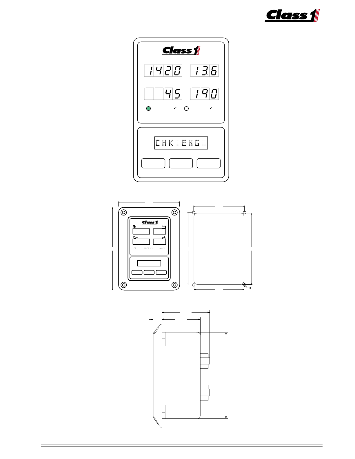
DISPLAYS
The Engine Status Center Display (ESC)
continuously shows Engine RPM, Oil Pressure, T emperature, and System V oltage on
four seven segment LED displays. The
mode of operation (English or Metric) is
indicated by an LED illuminated next to
the current mode.
ENGINE RPM
OIL PRESSURE
F)
ENGLISH
ENGINE STATUS CENTER
(PSI
VOLTS
ENG TEMP
(kPa
METRIC
C)
The Message Center is an eight charac-
ter alphanumeric display. In nor mal operation the message center will display a
logo.
If a Check Engine or Stop Engine malfunction occurs, Detroit Diesel Engines
transmit both of these messages on the
data bus , the displa y will read CHK ENG
or STOP ENG. Other Electronic Engines
may not tr ansmit these messages. To display Stop or Chec k engine messages for
these engines, connections must be made
from the engine ECM or cab indicators to
the ESC.
MESSAGE CENTER
ENGINE RPM
OIL PRESSURE
F)
ENGLISH
ENGINE STATUS CENTER
(PSI
VOLTS
ENG TEMP
(kPa
METRIC
C)
If a low oil pressure situation occurs, the
oil pressure display will alternate between
LOLO
the current oil pressure and
LO.
LOLO
If a high temperature condition dev elops,
the engine temperature display will toggle
between the temperature value and
HIHI
HI.
HIHI
A low voltage condition results in CHK
BA TT being displayed and the voltmeter
alternates between the actual voltage and
LOLO
LO.
LOLO
An overvoltage situation will display actual voltage alternating with
HIHI
HI on the volt-
HIHI
meter and CHK AL T will be sho wn in the
message center.
MENU
MENU
SILENCE
MESSAGE CENTER
SILENCE
SELECT
SELECT
The message center also displays menu
information when the menu switch is depressed. The menu ma y only be accessed
when engine speed is below 900 RPM.
The MENU switch scrolls through the menu
and the SELECT switch either selects the
item or toggles between choices. The
SILENCE switch sav es current data and ex-
its from the menu.
4
Page 5

CONNECTIONS
ESC harness connection to the apparatus is achieved b y the use of two connectors.
Deutsch DT06-4S 4 socket connector
Cavity Description ESC
A-1 Ignition P ower 12V In P ower for the ESC
A-2 System Ground Ground in Ground for the ESC
A-3 Data Link + J1587 in Data line positive
A-4 Data Link - J1587 in Data Line negative
Deutsch DT06-12S 12 socket connector
Cavity Description ESC
B-1 Plug
B-2 Plug
B-3 Plug
B-4 Check Engine Ground input from engine ECM
B-5 User Input Ground input from OEM
can be used for ST OP ENG
B-6 Plug
B-7 Plug
B-8 Plug
B-9 Ala rm Ground output to an OEM alarm
B-10 PTO engaged Positive input for PT O hours
B-11 User Hours Positiv e input for USER hours
B-12 Low Fuel Ground input for low fuel alert
B-4 is a ground input dedicated to the Check Engine Warning of the ESC. T o receiv e this
message on non-DDEC engines, you must provide this input.
B-5 is ground input that will display a generic warning message A UX IN. This can be any
warning signal that you wish the operator to receive. For example on a non-DDEC
engine, provide a ground input from the STOP Engine output of the engine ECM and
change the message to read STOP ENG if y ou want the Pump Operator to receive the
STOP ENGINE Message.
B-9 is a ground output to an OEM alarm.
B-10 is a positive (12 VDC) input that allows the ESC to accumulate PT O hours.
B-11 is a positive (12 VDC) input that will tally hours as long as the ESC and this input
are active. The displa y message can be customized by the OEM to indicate its usage .
B-12 is a ground input from a tank lev el s witch to alert the operator of a low fuel condi-
tion.
5
Page 6

Menu
The ESC Menu can be entered at any time that the engine is operating at 900 RPM or
less.
Enter the menu by pressing the
MENU switch.
Scroll through the menu by using the MENU switch.
Select items from the menu by using the SELECT s witch.
Save inf ormation and exit from the menu using the SILENCE switch.
Menu Items
MENU TEST L TS T est Displa y .
SELECT Illuminates all display segments, LEDs and sounds alarm.
MENU UNITS: (E or M) Select units for displa y.
SELECT T oggles English and Metric units.
MENU ALERT?: (Y or N) Enables or Disables
SELECT Toggles the Alert tone on or off.
Enables the Alert Tone to direct the attention of the operator to certain messages.
MENU HOURS View operating hours.
SELECT PTO HOUR SELECT display PT O hours
SELECT USER HR SELECT display USER hours
SELECT ENG HOUR SELECT display ENGINE hours
SELECT INCIDENT SELECT T=00:00 (hrs/mins)
Timer starts at power up, resets at power down.
MENU return to TEST L TS .
SILENCE at any point in the menu returns you to normal operation.
6
Page 7

MESSAGES
Alert Messages are preceded by a short
tone burst to alert the operator . The cause
for the alert is then displayed on the message center, alternating with other information.
Alert Messages:
PTO ENGD PTO engagement
CHK ENG Check Engine
LDMGR ON Load Management
T ANK LO W Tank Le vel
LM-LVL:x (1-8) Shed level
Alarm Messages are accompanied by a
pulsed alarm that continues until silenced
or the cause eliminated. The alarm message is displayed in the message center
and LO or HI is displayed on the appropriate display for temperature, oil and voltage alarms.
AUX IN ** User Input
LOW FUEL less than 1/4 tank
STOP ENG Stop Engine
CHK BA TT * System V oltage low
CHK AL T * System V oltage high
LOW OIL * Oil Pressure low
HI TEMP * T emperature high
Oil and Temp . alarms are active only with
engine running.
Normal Messages appear without any audible warning.
AUX HRS ** User hours
CLASS 1 ** Logo
SR VC PT O Service reminder for PTO
* Alarm P oints are set by the OEM. ** OEM configurable messages
Defaults Settings:
Service time Interval 100 hours
Aux. Input Displa y AUX IN
Aux. Hours Display A UX HR
Logo CLASS1
Low V oltage Alarm YES
T emper ature source DEG:OIL
Low Oil Pressure 10 PSI (69 kPa)
o
High T emperature 230
Low Voltage Alarm 11.9 VDC
Overvoltage 15.0 VDC
F (110 oC)
7
Page 8

ESC Po wer
A-1 circuit
A-2 circuit
These are the power and ground inputs f or ESC operation and they also
provide system voltage inf ormation to the ESC for display.
ESC Data
A-3 circuit
A-4 circuit
Engine information is received electronically on the J-1587 data bus .
Check Engine W arning
B-4 circuit
This input (ground) must be active f or a check engine warning on all
engines except Detroit Diesel
.
Auxiliary Input
B-5 circuit
This input (ground) is used for an auxiliary device activ e or warning mes-
sage (configurable by the OEM).
SYSTEM OPERATION
Alarm Output
B-9 circuit
This output (ground) should be active when TEST L TS is selected f orm the
menu. The alarm can be deactivated during operation by the user .
PTO HRS
B-10 circuit
This input must be active (+ 12 VDC) when the PTO is engaged to log hours
and display the PT O ENGD message.
Auxiliary Hours
B-11 circuit
This input (+ 12 VDC) can be used f or any de vice that you want to monitor .
The message is configurable by the OEM.
Low Fuel
B-12 circuit
This input (ground) will display a LO W FUEL alert message when active.
8
Page 9

NOTES
Notes:
The engine information is “read” from the engine ECM. If some information is displayed then the ESC is functioning properly . Missing information is the result of an engine broadcast not being sent or a message header not in the
proper format. If temperature is missing chec k that the source (oil or w ater) is configured properly .
The voltage displayed is taken from the inputs at A1 and A2. It may vary from battery voltage dependent on the
voltage drops in the wiring. The alarm points can be changed by the OEM to suit the end user .
The LOW FUEL input would normally be tied to a low fuel switch in the tank. This can be part of a sending unit or
a separate switch.
The USER INPUT can be used for any purpose. It can be tied to a temperature switch on the transmission and
labelled HOT TRNS or something to that eff ect.
The AUX HRS input can be tied to an ything. An auxiliary generator or hydr aulic pump for instance. The label can
be changed and then hours on that equipment can be tracked.
c:\manuals\esc\esc_mnl.p65 02022000
9
 Loading...