

Page 1
Engineering
Standards
Name ENFO III
Identifier Installation Information
Engineering Standard Number
C1-103817
VOLTSENGINE RPM
TEMPOIL PRESS
ENGLISH
(PSI - F)
ENFO III
oo
METRIC
(kPa - C)
page 1 of 4 pages
Page 2
Engineering
Standards
Name ENFO III
Identifier Installation Information
‘s
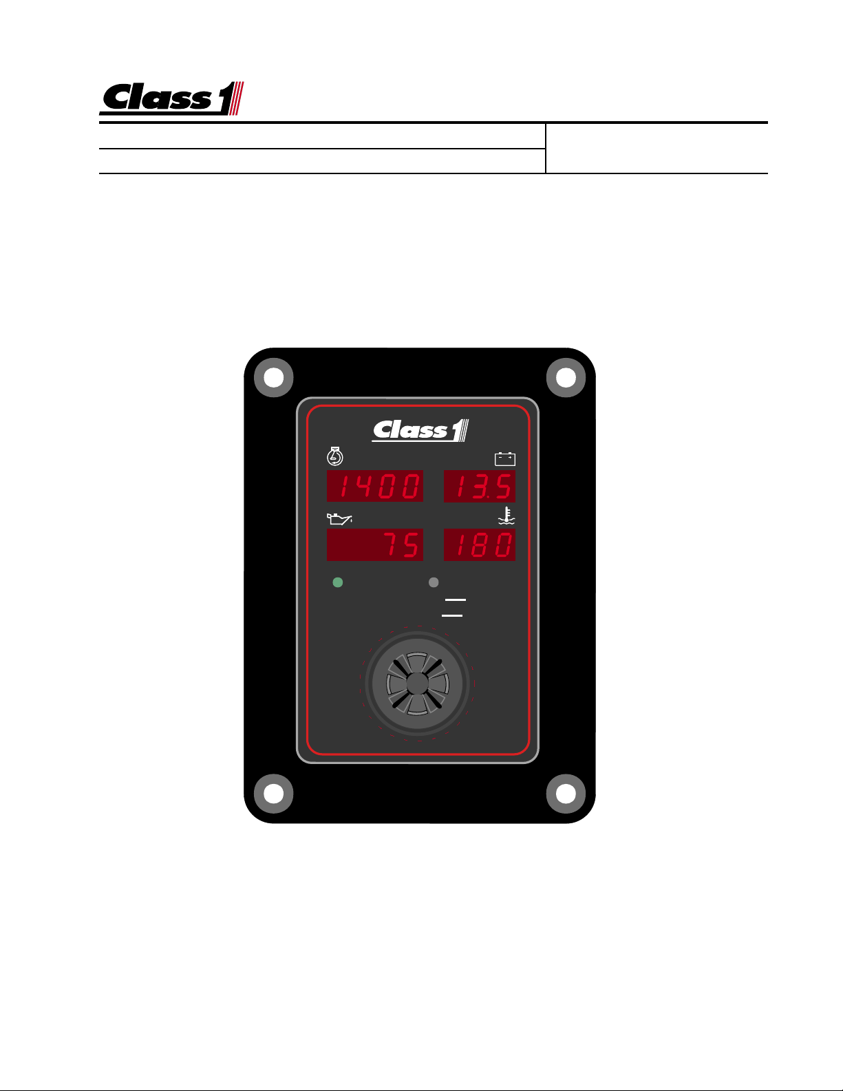
ENFO III
provides the pump operator with electrical system and
Engineering Standard Number
C1-103817
engine operating information in a single unit that includes an alarm.
þ Engine RPM Display
þ System Voltage Display and Alarm
þ Engine Oil Pressure Display and Alarm
þ Engine Temperature Display and Alarm (Oil or Coolant )
þ English Display
4.437
VOLTSENGINE RPM
TEMPOIL PRESS
oo
(PSI - F) (kPa - C)
6.000
ENGLISH
METRIC
ENFO III
The
Class1
Pump Panel Operator. Visual and Audible Alarms are available for critical information. The
ESC utilizes the SAE J-1587 data link for engine information and the power and ground for
the unit provide voltage information.
ENFO
III is a convenient self contained Engine information display for the
page 2 of 4 pages
Page 3

Engineering
Standards
Name ENFO III
Identifier Installation Information
Installation
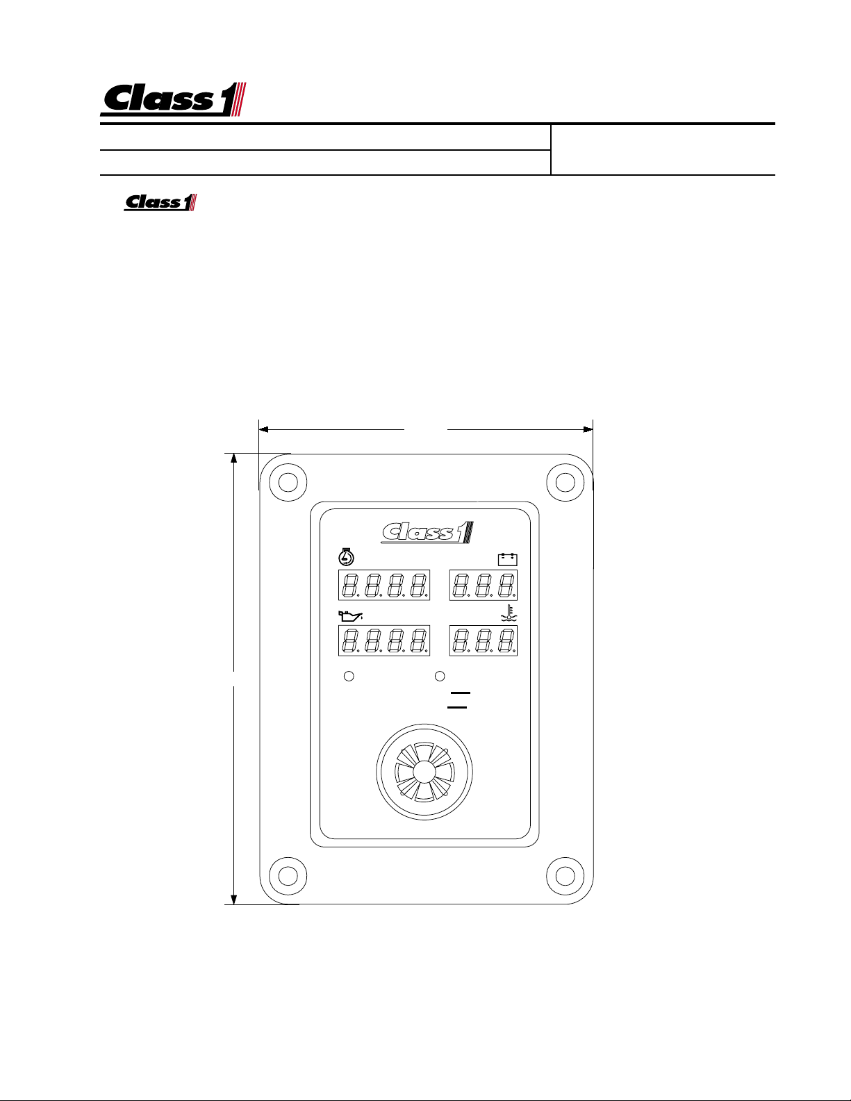
The display mounts in a 3.62” by 5.2” cutout.
Overall area necessary for installation is 4.5” by 6.0”.
Four 0.201d holes are provided for mounting screws.
Engineering Standard Number
C1-103817
3.687
5.250
MOUNTING HOLES AND
CUT-OUT DIMENSIONS
Ø 0.201"
3.618
5.180
page 3 of 4 pages
Page 4

Engineering
Standards
Name ENFO III
Identifier Installation Information
Engineering Standard Number
C1-103817
ENFOIII harness connection to the apparatus is achieved by the use of a Deutsch four (4)
pin socket connector.
Deutsch DT06-4S 4 socket connector
CavityDescription ESC
A-1 Ignition Power 12V In Po wer f or the ENFOIII
A-2 System Ground Ground in Ground for the ENFOIII
A-3 Data Link + J1587 in Data line positive
A-4 Data Link - J1587 in Data Line negative
A-1 circuit
A-2 circuit
These are the power and ground inputs for ENFOIII operation and they also
provide system voltage inf ormation to the ENFOIII for displa y.
ESC Data
A-3 circuit
A-4 circuit
Engine information is received electronically on the J-1587 data bus.
The
ENFO III
continuously shows Engine RPM, Oil Pressure, T emper ature, and System
Voltage on four seven segment LED displays.
The
ENFO III
will determine whether to source coolant or oil for temperature automatically.
The mode of operation (English or Metric) is indicated by an LED illuminated next to the
current mode.If a low oil pressure situation occurs (<10 PSI), the oil pressure display will
alternate between the current oil pressure and
LOLO
LO
and the alarm will activate.
LOLO
If a high temperature condition develops (235 deg. F), the engine temperature display will
toggle between the temperature value and
HIHI
HI
and the alarm will activate.
HIHI
A low voltage condition (<11.9 VDC) results in an audible alarm and the voltmeter alternating between the actual voltage and
LOLO
LO
LOLO
.
page 4 of 4 pages
 Loading...