

Page 1

Standard Features
Main Battery bank monitoring
Isolated Battery monitoring
Electrical Load Sequencing
Electrical Load Shedding
Over Voltage Indication
High Idle Control
Automatic or Manual Reset Modes
Reverse Polarity / Short Circuit Protected
Rugged Metal Enclosure
LED Status Display
Battery Warning
A vailable Features
Positive or Ground Master Switch
Integral Relay Distribution Board
Positive or Ground Output for Loads
1
Page 2

Standard Features
Sequence (J3d)
This mode will performs the function of sequencing the electrical loads on
and off.
Automatic Load Reset (J2b)
Any load which has been shed will automatically be controlled off for a minimum of five minutes, regardless of the state of the electrical system. After the
electrical system becomes stable, the loads will be controlled back on by the
system. Any shed load can be turned on immediately by performing a manual
load reset (see next section).
Manual Load Reset (J2a)
When this mode is enabled, any load which has been shed will remain off
until the system manager is manually reset.
Manually Resetting the System
There are two levels of manual reset. LOAD RESET and FULL RESET.
Load Reset: The shed loads are manually reset by toggling the master switch
off and then on again within two (2) seconds. When a load reset is performed, all loads which are currently shed of will be sequenced on. The
system manager will refrain from shedding any load for fifteen minutes. After
fifteen minutes, normal operation of the system manager will resume.
Full Reset: Full system reset will occur when the master switch is turned off for
at least two seconds. After full reset, the loads will be sequentially turned off
and the system will resume normal operation when the master switch is toggled
to the on position.
Over-Voltage Indicator (J4d)
The system manager continually monitors the system voltage and will activate an output when it detects that the constant system voltage has increased
above 14.5 volts. As in all modes, the system will not react to the spurious
voltage transients which may exist in the electrical system as loads and devices are cycled.
Fast Idle Control (J4c)
The system manager is capable of becoming a part of a system which controls a fast idle device. The fast idle output will activate whenever the system
voltage is low. The output will deactivate if the system manager is reset or the
voltage becomes good.
This circuit must only be utilized when the appropriate interlocks are present.
2
Page 3
Battery Warning
The Battery Warning feature is a special output which indicates different states
of the electrical system. The Class 1 system manager continuously monitors
the rate of discharge (voltage drop per unit time) of the electrical system. The
Battery Warning indicator will flash at a rate proportional to the discharge rate.
More simply, the faster that the voltage is dropping, the faster the indicator will
flash.
When sudden voltage drops are recognized by the system, the light will flash
quickly for three seconds to indicate an instantaneous voltage drop. After the
quick flash, the indicator will rever t back to its previous flash rate.
Once the voltage has dropped to a critical level which requires loads to be
shed, the indicator will burn steady and remain on as long as there are loads
in the shed state or loads are in the manual reset state and voltage is low.
The Battery Warning option can assist an operator in identifying a potential
low voltage situation in advance giving the opportunity to react to a poor
voltage situation before it happens.
NOTE: Refer to the section titled “Specifications” at the end of this manual for
more descriptive information on these available modes.
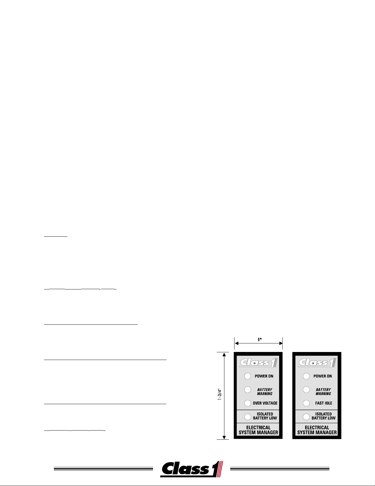
The indicator panel consists of four LED’s:
POWER ON (GREEN WIRE)
This LED illuminates when power is applied to the
System Manager.
BATTERY WARNING (YELLOW WIRE)
This LED is connected to terminal TB#8 and flashes
when system voltage drops below 13.2 VDC.
ISOLATED BATTERY LOW (BLUE WIRE) OPTION
This LED is connected to TB#7 and illuminates
when an auxiliary battery’s voltage drops below
11.8 VDC for more than two minutes.
ST ANDARD P ANEL DISPLA Y
The Class1 Electrical System Manager is supplied with an indicator
panel.The indicator panel is designed
to fit in a standard rocker s witch cutou t (7/8” x 1-1/2”).
OVER-VOLTAGE OR FAST IDLE (BROWN WIRE)
This LED is connected to TB#15.
GROUND (BLACK WIRE)
Connected to a good ground source.
3
Page 4
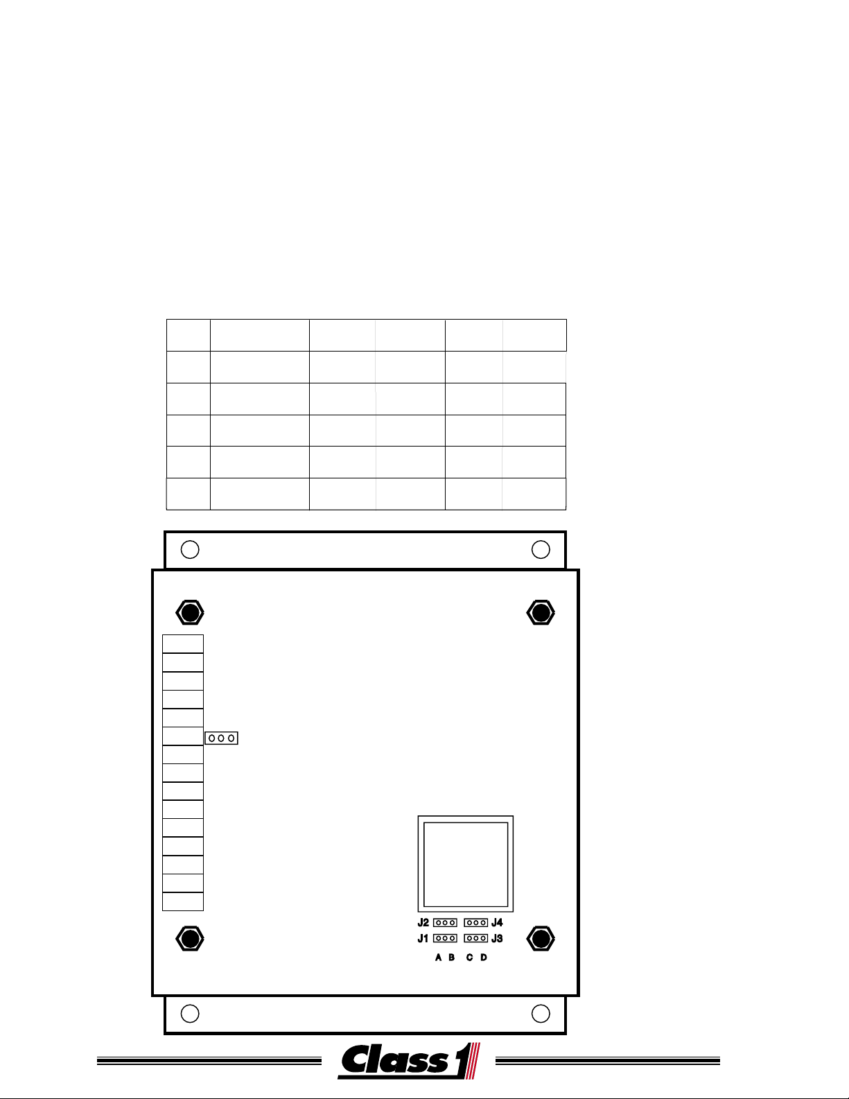
System Configuration
The Electrical System Manager is configured by the use of five jumpers
labeled J1 through J5.
J1 and J5 control battery monitoring (MAIN or MAIN and ISOLATED.)
J2 controls the load reset method (MANUAL or AUTOMATIC.)
J3 controls Load Sequencing (OFF or ON.)
J4 controls when Terminal bar #15 is active (Low Voltage or High Voltage.)
The System Manager cover must be removed to change its operating mode.
J1 through J4 are located at the lower right edge of the circuit board, J5 is
located next to TB #10.
JMP DESCRIPTION
J1
J2
J3
J4
J5
TB#15
TB#14
TB#13
TB#12
TB#11
TB#10
TB#9
TB#8
TB#7
TB#6
TB#5
TB#4
TB#3
TB#2
TB#1
BATTERIES MAIN
RESET
SEQUENCE
TERMINAL #15
FUNCTION
JUMPERS
B
A
J5
POSITION
A
MANUAL
MAIN
POSITION
B
MAIN/
ISOLATED
AUTO
MAIN/
ISOLATED
POSITION POSITION
C
OFF
FAST IDLE
CONTROL
D
ON
OVER-VOLT
LIGHT
MODE CONFIGURATION
Figure1
4
Page 5
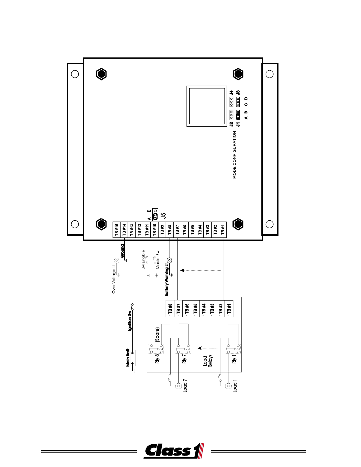
Main Battery Only Configuration
Relay 1
Relay 6
Load
Relays
Dash
Switches
Load SW 1
Load SW 6Load SW 6
Jumper J1 and J5 are
placed in pos. A.
This provides for seven
load control outputs that
can be sequenced and
shed. These outputs are
at terminals #1 through #7.
The complete terminal descriptions for this mode
are shown in Figure 2,
and one method of wiring
is shown in Figure 3.
Over Voltage Lgt/
High Idle Control
Ground
Ignition
No Connection
Shed Enable
Master Switch
System Override
Battery Warning Lt
Load Level 7
Load Level 6
Load Level 5
Load Level 4
Load Level 3
Load Level 2
Load Level 1
TB #15
TB #14
TB #13
TB #12
TB #11
TB #10
TB #9
TB #8
TB #7
TB #6
TB #5
TB #4
TB #3
TB #2
TB #1
A
J5
B
MODE CONFIGURATION
J2 J4
J1
ACBD
J3
Figure 2
5
Page 6

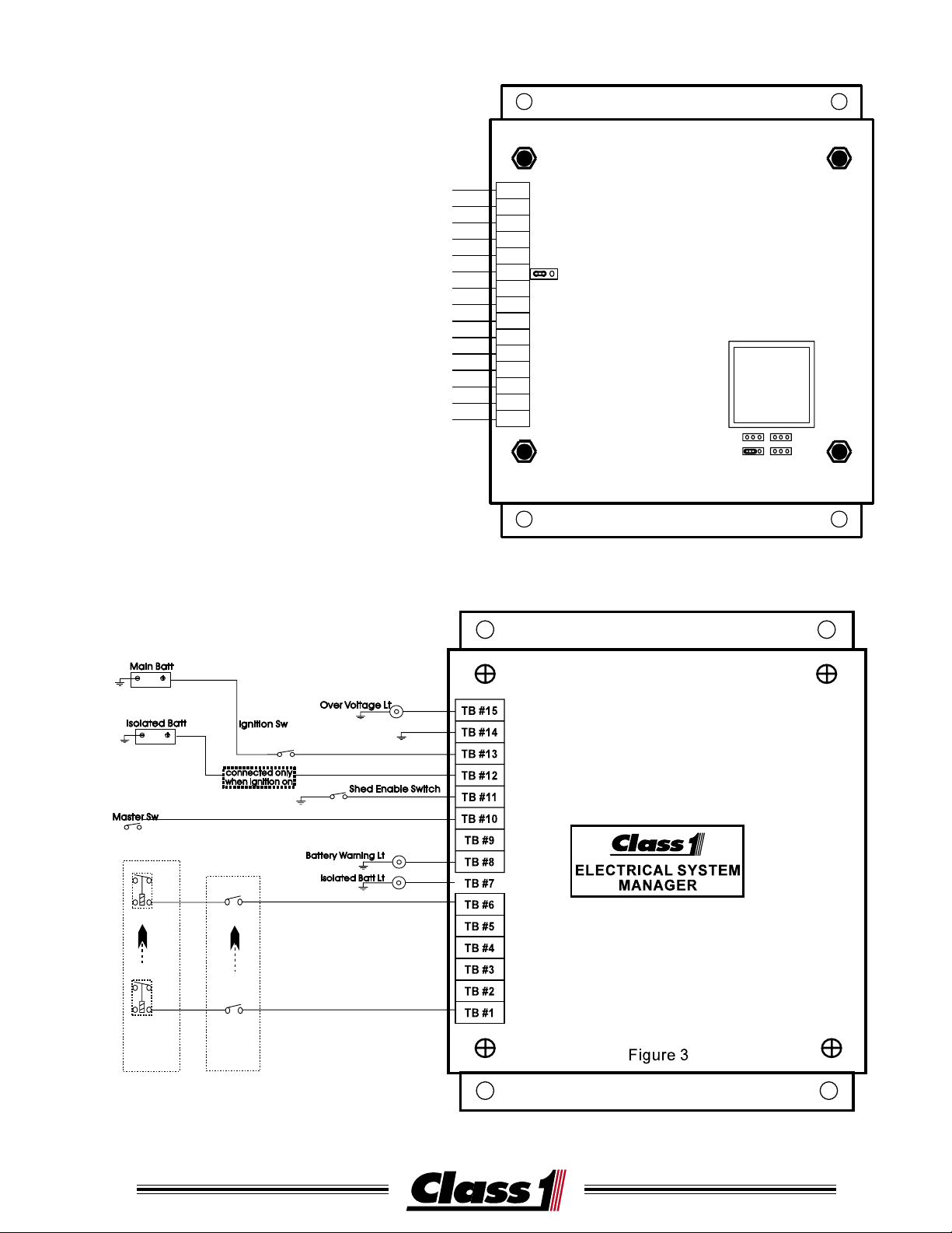
MAIN AND ISOLATED BATTERY CONFIGURATION
Jumper J1 and J5 are placed in position B.
The system manager will operate in main and isolated battery mode. This
provides for six load control outputs which can be sequenced and shed. A
separate input for the isolated battery is located at TB#12 and an output for
low isolated battery is located at TB #7. One method of wiring is shown in
Figure 5.
TB#15
TB#14
Over Voltage Lt
Ignition Sw
TB#13
TB#12
connected only
when ignition on
TB#10
TB#9
TB#11
Shed Enable Switch
ELECTRICAL SYSTEM
MANAGER
TB#7
TB#8
Battery Warning Lt
TB#6
Isolated Batt Lt
Load Sw 6
TB#5
TB#4
TB#3
TB#1
TB#2
Load Sw 1
Figure 5
Dash Switches
Main Batt
Rly 6
Isolated Batt
Master Sw
Rly 1
Load Relays
6
Page 7

Electrical System Manager II
Relay Coil Input
Relay LED©s
The Electrical System Manager II is equipped
with 8 Printed Circuit Board Relays mounted in
an enclosure with the load manager. The relay coil input tab should be grounded for normal installations. The common and output tabs
on each relay readily allow for custom installations.
COM
COM
COM
COM
1
N O
N C
2
N O
N C
3
N O
N C
4
N O
N C
5
N O
COM
1
2
3
4
5
6
7
8
COM
COM
N C
6
N O
N C
7
N O
N C
8
N O
COM
N C
Over Voltage Light
High Idle Control
Ground
Ignition
No Connection
Shed Enable
Master Switch
System Override
Battery Warning Lt
Load Level 7
Load Level 6
Load Level 5
Load Level 4
Load Level 3
Load Level 2
Load Level 1
TB#15
TB#14
TB#13
TB#12
TB#11
TB#10
TB#9
TB#8
TB#7
TB#6
TB#5
TB#4
TB#3
TB#2
TB#1
A
J5
B
MODE CONFIGURATION
Figure 4
7
Page 8
Electrical System Manager II
8
Page 9

Terminal Block I/O Polarity
Negative Master Switch and Positive Output
PN 100633 ESM / PN 100756 ESM II
TB #15 + Output Overvoltage light or Fast idle control
TB #14 - Input System Ground
TB #13 + Input Ignition (Main battery monitor voltage)
TB #12 + Input Isolated Battery monitor voltage
TB #11 - Input Load Manage Enable (shed)
TB #10 - Input Master Switch
TB # 9 + Input System Override
TB # 8 + Output Batter y Low Warning Light
TB # 7 + Output Load 7 or isolated battery low light
TB # 6 + Output Load 6
TB # 5 + Output Load 5
TB # 4 + Output Load 4
TB # 3 + Output Load 3
TB # 2 + Output Load 2
TB # 1 + Output Load 1
Positive Master Switch and Positive Output
PN 100767 ESM / PN 101038 ESM II
NOTE:LOADS 1 & 2 DO NOT SHED, MAIN BATTERY MONITORING ONLY.
LOADS SEQUENCE ON 1-7, SEQUENCE OFF 7-1 AND SHED 7-3.
TB #15 + Output Overvoltage light or Fast idle control
TB #14 - Input System Ground
TB #13 + Input Ignition (Main battery monitor voltage)
TB #12 + Input Master Switch
TB #11 - Input Load Manage Enable (shed)
TB #10 No Connection
TB # 9 + Input System Override
TB # 8 + Output Batter y Low Warning Light
TB # 7 + Output Load 7
TB # 6 + Output Load 6
TB # 5 + Output Load 5
TB # 4 + Output Load 4
TB # 3 + Output Load 3
TB # 2 + Output Load 2
TB # 1 + Output Load 1
9
Page 10

Terminal Block I/O Polarity
Negative Master Switch and Ground Output
PN 101084 ESM
TB #15 + Output Overvoltage Light or Fast Idle Control
TB #14 - Input System Ground
TB #13 + Input Ignition (Main battery monitor voltage)
TB #12 + Input Isolated Battery monitor voltage
TB #11 - Input Load Manage Enable (shed)
TB #10 - Input Master Switch
TB # 9 - Input System Override
TB # 8 - Output Batter y Low Warning Light
TB # 7 - Output Load 7 or isolated batter y low light
TB # 6 - Output Load 6
TB # 5 - Output Load 5
TB # 4 - Output Load 4
TB # 3 - Output Load 3
TB # 2 - Output Load 2
TB # 1 - Output Load 1
Positive Master Switch and Ground Output
PN 101119 ESM
NOTE:LOADS 1 & 2 DO NOT SHED, MAIN BATTERY MONITORING ONLY.
LOADS SEQUENCE ON 1-7, SEQUENCE OFF 7-1 AND SHED 7-3.
TB #15 + Output Overvoltage light or Fast idle control
TB #14 - Input System Ground
TB #13 + Input Ignition (Main battery monitor voltage)
TB #12 + Input Master Switch
TB #11 - Input Load Manage Enable (shed)
TB #10 No Connection
TB # 9 - Input System Override
TB # 8 + Output Batter y Low Warning Light
TB # 7 - Output Load 7
TB # 6 - Output Load 6
TB # 5 - Output Load 5
TB # 4 - Output Load 4
TB # 3 - Output Load 3
TB # 2 - Output Load 2
TB # 1 - Output Load 1
10
Page 11

SPECIFICATIONS
OPERATING VOLTAGE
7.5 to 20 Volts DC
OUTPUTS
High Side Drivers Vmain @ 0.5 amp (source)
Low Side Drivers Ground @ 0.5 amp (sink)
ISOLATED BATTERY INPUT
0 to 20 Volts DC
TRANSIENT SUPPRESSION
Outputs are protected against thermal overload, direct shorts and transient
spikes from -50 to 60 Volts DC.
LOAD CONTROL
Loads will be cycled on whenever the Master Switch is activated.
The System Manager will control loads and the high idle function only when
the Shed Enable input (terminal #11) is active.
Loads are shed from lowest priority to highest priority, level 1 to level 7,
except for units with a positive master switch, they shed level 7 to level 3.
The voltage points are respectively:
L1-12.2, L2-11.95, L3-11.70, L4-11.45, L5-11.25, L6-11.10 and L7-10.95
VDC. Voltage must drop below the shed point for 30 seconds for a load to
shed and voltage must be above the shed point for 60 seconds for a shed
load to unshed.
NOTE: The unit can be configured so that the loads can be turned on only by a manual
reset.
No automatic recycling
MANUAL LOAD RESET
Toggling the Master Switch off and then on again within 2 seconds manually resets the loads. Loads that were shed off will be cycled on and the
high idle control will be reset. The System Manager will disable itself for 15
minutes.
MANUAL FULL RESET
Toggling the Master Switch off for more than 2 seconds will cycle all loads
off. The system will return to normal operation when the Master Switch is
toggled back to the on position.
NOTE: A signal applied to terminal #9 (system override) will force allloads ON,
completely bypassing all load control functions of the unit.
11
Page 12

SPECIFICATIONS
TERMINAL BLOCK #15
This output becomes active for the overvoltage light (high voltage) or for high
idle control (low voltage) dependent on the setting of jumper J4.
OVER-VOLTAGE INDICATOR
Activates at 14.5 VDC and deactivates at 14.0 VDC.
HIGH IDLE CONTROL
The output will activate when the voltage drops below 12.3 VDC for more
than 1 minute. The output will remain ON for a minimum of 5 minutes
until the voltage exceeds 13.0 VDC.
NOTE: This output must only be used in conjunction with the appropriate
safety interlocks for the intended application.
AUXILIARY BATTERY
When an auxiliary batter y is present and the system is configured for it, The
System Manager will monitor the auxiliary battery. Output (TB #7) is turned
on when the battery voltage drops below 11.8 VDC for more than 2 minutes.
The output will remain on for a minimum of 5 minutes and until the isolated
battery voltage is greater than 12.5 VDC. If the main battery bank voltage
exceeds 13 VDC, the output will deactivate and the system will then recheck
the isolated battery voltage after a short delay. This allows the system to
become part of a battery separation solenoid system.
and
NOTE: When configured to monitor a second batter y source, only 6 loads
can be controlled as output #7 is utilized for the isolated battery
indicator. All other functions are unchanged.
BATTERY LOW WARNING LIGHT
Output from TB #8 is disabled when the monitored voltage is above 13.2
VDC. Below this level, the output will flash to indicate a voltage drop. The
output will flash at a varying rate proportional to the discharge rate of the
battery. If the system detects a large instantaneous voltage drop, the light will
flash rapidly for 3 seconds and then rever t to its current flash rate.
NOTE: The output will remain steady if any load has been controlled off
or
the system has been manually reset.
12
Page 13

MODELS AND FUNCTIONS
A vailable System Managers
and System Manager II’s
-nimreT
la
noitcnuFO/I
y
kcolB
51thgilegatlovrevOtuptuOevitisoP
lortnocelditsaFtuptuOevitisoP
41dnuorGmetsyStupnIdnuorG
31
21yrettabdetalosItupnIevitisoP
11
01hctiwSretsaMtupnIdnuorG
daoL(
niam(noitingI
)yrettab
hctiwSretsaMtupnIevitisoP
elbanEdehS
)tnemeganaM
tupnIevitisoP
tupnIdnuorG
1
0
0
6
3
3
1
0
0
7
5
6
1
0
1
0
8
4
1
0
0
7
6
7
1
0
1
0
3
8
-tiraloP
XXXXXX
XXXXXX
XXXXXX
XXXXXX
XXX
XXX
XXXXXX
XXX
1
0
1
1
1
9
9edirrevOmetsyStupnIevitisoP
tupnIdnuorG
8
7
1-7
woL
woLyrettaB
thgiLgninraW
yrettaBdetalosI
1daoL-7daoLtuptuOevitisoP
tuptuOevitisoP
tuptuOevitisoP
tuptuOdnuorG
tuptuOdnuorG
XX
X X
XXXXXX
XX
X
XX XX
X X
XX
13
Page 14

Note:
SAMPLE CIRCUITS
A/C Control Circuit
Aux Control
Relay
As A/C control circuits vary by vehicle, the circuit shown is
representative only of one method which can be utilized to
interrupt the A/C control circuit. It is the responsibility of the
installer to utilize properly rated relays or circuit breakers in
the installation.
The loading on output #15 should not exceed 0.5 amps.
Alternator
Starter
Ignition Sw
BATT SEPARATOR SOLENOID
POWER TO VEHICLE LOADS
+
-
+
-
+
-
+
-
+
-
+
-
Batt Ground
POWER TO SEPARATED LOADS
TB#15
TB#14
TB#13
TB#12
TB#11
TB#10
TB#9
TB#8
TB#7
TB#6
TB#5
TB#4
TB#3
TB#2
TB#1
14
Page 15

Fast Idle
Switch
OEM Fast Idle
Interlocks
OEM Fast
Idle Circuit
SAMPLE CIRCUITS
Ground
Relay
PSI Switch closed
when Park Brake set
Ignition
Shed Enable
Relay
TB#15
TB#14
TB#13
TB#12
TB#11
TB#10
TB#9
TB#8
TB#7
TB#6
TB#5
TB#4
TB#3
TB#2
TB#1
Signal From Brake Lights
Automatic FAST IDLE CIRCUIT, disabled when service brake is applied
15
 Loading...