

Page 1
Engineering
Standards
Name Tank Level Display
Identifier Installation Information
Installation
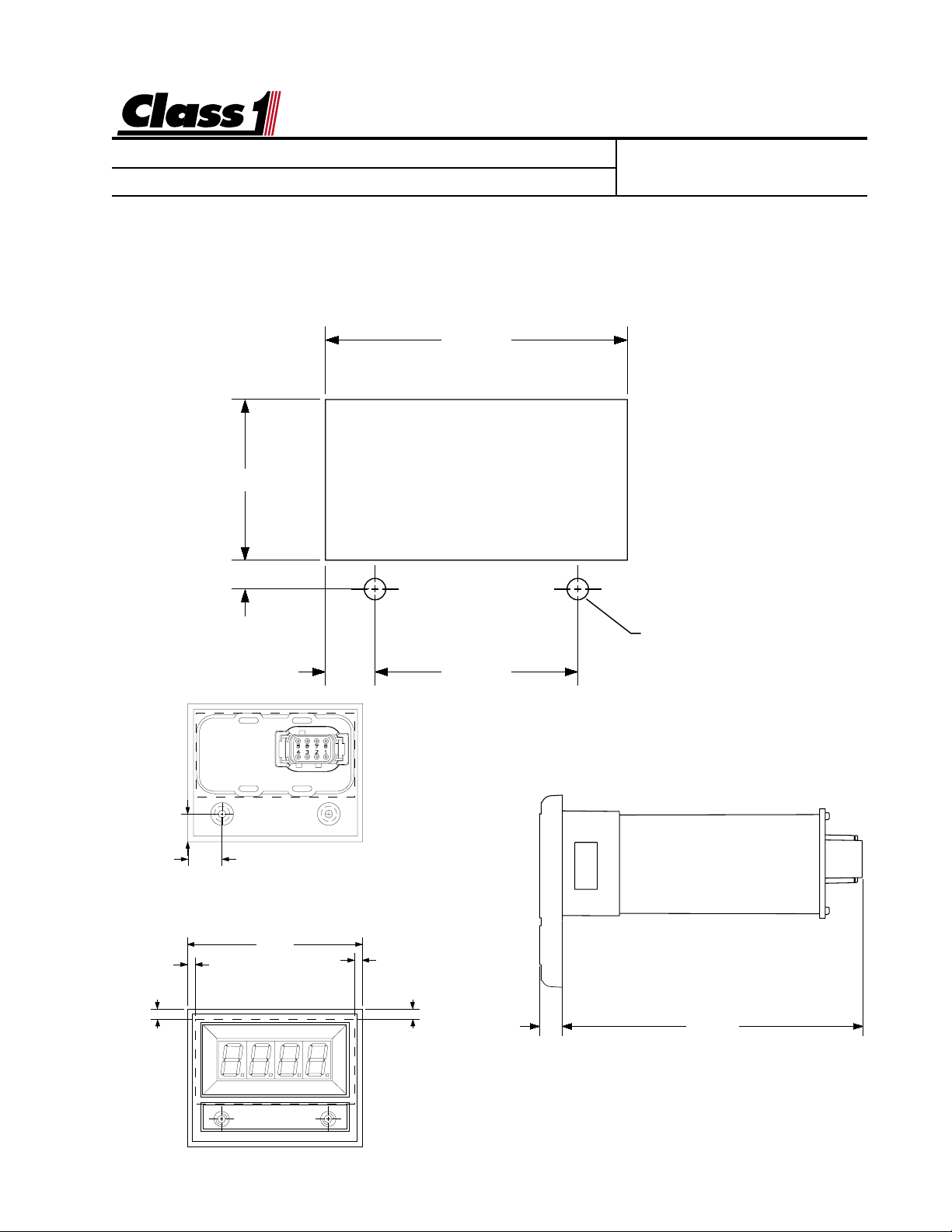
The display mounts in a 2.84” by 1.51” cutout.
Overall area necessary for installation is 3.2” by 2.5”.
Two 0.201d holes are provided for mounting scre ws.
1.510
.277
Engineering Standard Number
C1-102245-A
2.840"
0.496"
0.142"
Ø 0.201"
(2) HOLES
.470 1.900
0.612"
3.125"
0.142"
0.182"0.182"
0.285" 3.832"
page 1 of 5 pages
Page 2
Engineering
Standards
Name Tank Level Display
Identifier Installation Information
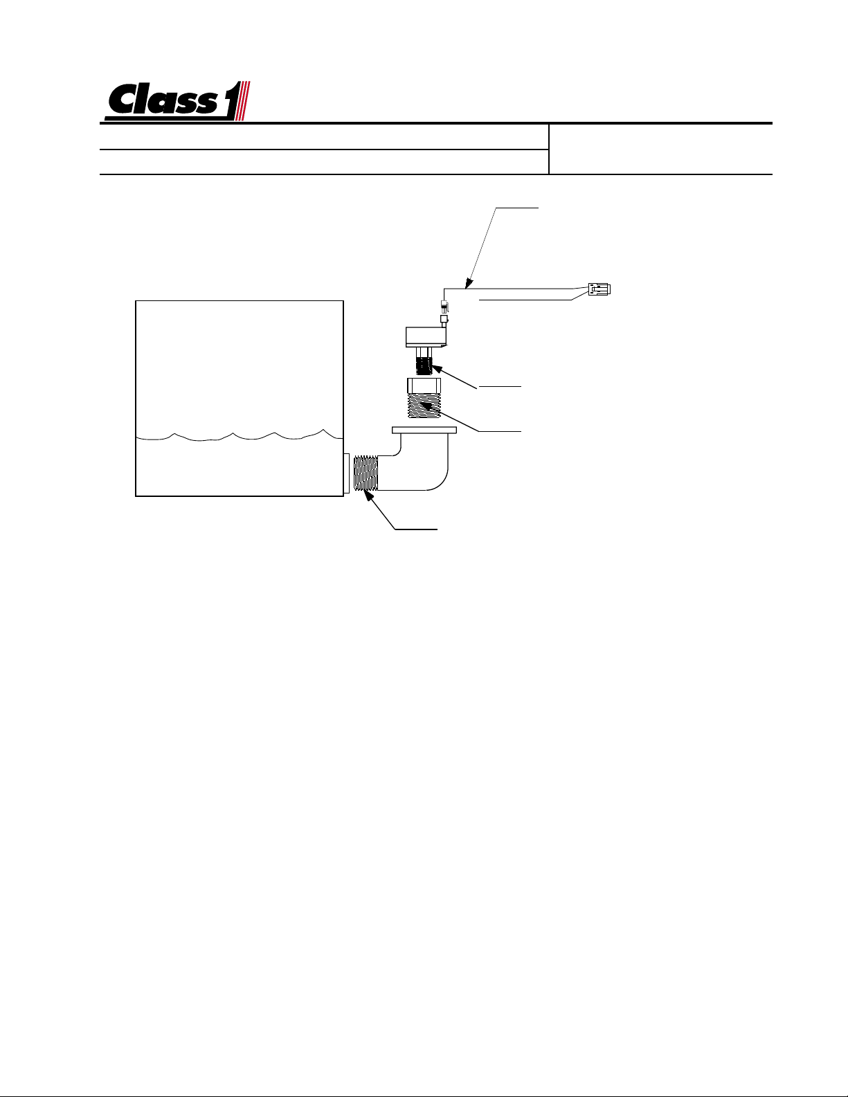
Tank Level Gauge
Transducer Installation
FLUID TANK
Engineering Standard Number
C1-102245-A
Harness
102193 5'
102194 10'
102195 20'
Pressure Transducer
1/4 NPT
Adapter 3/4-1/4 NPT Bushing (OEM)
Foam adapter is supplied when a
foam level system is ordered.
3/4 NPT Elbow (OEM)
The transducer must be mounted vertically as depicted to insure an accurate and reliable reading.
This will also prevent damage to the transducer from freezing.
The transducer measures the column of water in the tank above the opening of the elbow.
When calibrating for a full tank it is important that the tank not be overfilled. If the fill opening or
tank vent is above the transducer, care should be taken not to have water in this area when
calibrating the tank level gauge. The transducer should never be mounted in the sump area
because of sludge and potential inaccuracies in calibration.
Mount a 3/4 NPT elbow just off the bottom of the tank, enough to keep sediment out of the
elbow and transducer (PN 102162). Attach a 3/4 to 1/4 NPT adapter (supplied for foam) to the
elbow and mount the transducer to that. The elbow and adapter need to be installed so that
the transducer is mounted vertically.
Pressurized Tanks
If you have a pressurized tank, two pressure transducers (PN 102471) can be used to compensate for pressure or vacuum in the tank. One transducer should be mounted near the
bottom of the tank and one near the top.
Use “Y” harness (PN 102439) and two (2) (PN 102455) transducer harnesses for wiring this
application.
When calibrating the dual transducer installation, the tank should be vented to the atmosphere.
page 2 of 5 pages
Page 3

Engineering
Standards
Name Tank Level Display
Identifier Installation Information
Electrical
The Aerial Warning Display is connected to the OEM harness with a Deutsch 8 pin
mini-connector.
Mating Connector: DTM06-08S
Locking Wedge WM-8S
Mating Terminal: 0462-201-20141 20 gauge socket
Engineering Standard Number
C1-102245-A
Location of magnetic switches
0 25 50 75 100
BAR GRAPH DISPLAY
Mating connector viewed from the wire end
page 3 of 5 pages
Page 4

Engineering
Standards
Name Tank Level Display
Identifier Installation Information
Calibration
Basic Calibration:
With the fluid tank empty, enter the
calibration password.
L L L R R R
The left (0%) bar will flash to indicate
that you are ready to calibrate for an
empty tank.
Activate the right switch followed by
the left switch.
The right (100%) bar will flash to indicate that the display is ready to calculate for a full tank.
When the tank is full, actuate the right
and then the left switch.
Calibration is complete.
If after checking the accuracy of your
calibration, you are not satisfied, then
you can perform the advanced calibration procedure. This is rarely necessary except in the case of oddly
shaped tanks.
NOTE: Calibration is based on
the weight of the column of water
immediately above the transducer.
If the unit is calibrated with a water
level that is temporarily higher
than normal, this will result in an
inaccurate display.
Engineering Standard Number
C1-102245-A
Advanced Calibration:
With the fluid tank empty,
enter the calibration password.
L L R R L L
The left (0%) bar will flash to indicate
that you are ready to calibrate empty.
Activate the left switch followed by
the right switch.
The fifth bar from the left (25%) will
flash to indicate that the display is
ready to calculate for a quarter tank.
Fill the tank to 1/4 full, actuate the
right and then the left switch.
The tenth bar from the left (50%) will
flash to indicate that the display is
ready to calculate for a half tank.
Fill the tank to 1/2 full, actuate the
left and then the right switch.
The fifteenth bar from the left (75%)
will flash to indicate that the display
is ready to calculate for three four ths
tank.
Fill the tank to the 3/4 full, actuate
the right and then the left switch.
The right (100%) bar will flash to indicate that the display is ready to calculate for a full tank.
When the tank is full, actuate the right
and then the left switch.
Calibration is complete.
page 4 of 5 pages
Page 5

Engineering
Standards
Name Tank Level Display
Identifier Installation Information
Engineering Standard Number
C1-102245-A
The tank level gauge has a bar traveling back and f orth across the display .
There is a problem with the pressure transducer (PN 102162) or wiring. At the
transducer connector , check for 5 VDC between pins A (+5 VDC) and pin B
(ground). These are sent from the displa y and must be of the correct polarity for
the transducer to function. Plug the connector into the transducer and check f or
voltage between Pin B (sensor ground) and pin C (sensor signal) at the transducer. With an empty tank, this voltage should be between 500 mV and 900 mV, if
it is not, replace the transducer. Check for v oltage at the display betw een pin 6
(sensor ground) and pin 2 (signal). With an empty tank, this voltage should be
between 500 mV and 900 mV. If it is not, check the wiring from the transducer to
the display. If the correct v oltage is present at pin 2, replace the displa y.
The T ank Level Gauge does not change or calibrate.
There is a problem with the pressure transducer or wiring. At the transducer
connector, chec k for 5 VDC between pins A (+5 VDC) and pin B (ground). These
are sent from the display and must be of the correct polarity for the tr ansducer to
function. Plug the connector into the transducer and check f or voltage at the
display between pin 6 (sensor g round) and pin 2 (signal). With an empty tank, this
voltage should be between 500 mV and 900 mV. As the water le vel in the tank
increases, the voltage should increase. If it does not, then replace the transducer
If the voltage increases, and the displa y does not change, attempt to calibrate the
unit. If calibration does not correct the problem, replace the displa y.
8
7
6
5
Wire Insertion View
1
2
3
4
page 5 of 5 pages
 Loading...