

Page 1
Engineering
Standards
Name
Identifier OEM Installation and Calibration
Digital Speedometer Information
1. Scope
This document addresses the
bration, and operation of this unit.
Class1
2. Purpose
The purpose of this document is to provide the OEM with enough information to allow
him to install this device and provide it to the end user fully operational and calibrated.
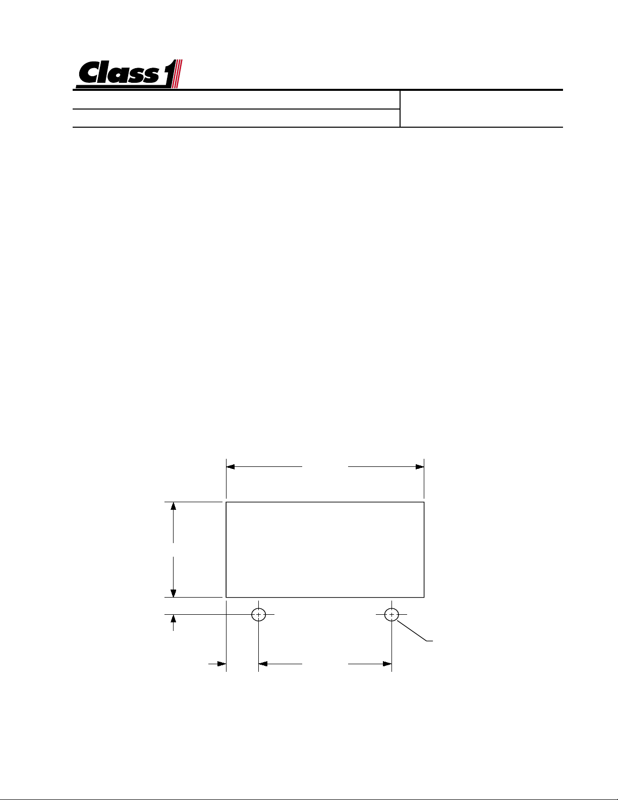
3. Display Installation
The speedometer display mounts in a by 2.84” by 1.51” cutout.
Overall area necessary for installation is 3.2” by 2.5” and a depth of 5 inches.
Two 0.201 diameter holes are provided for mounting scre ws.
Engineering Standard Number
C1-102007-A
digital speedometer and the installation, cali-
1.510
.277
2.840"
Ø 0.201"
(2) HOLES
.470 1.900
page 1 of 4 pages
Page 2
Engineering
Standards
Name
Identifier OEM Installation and Calibration
Digital Speedometer Information
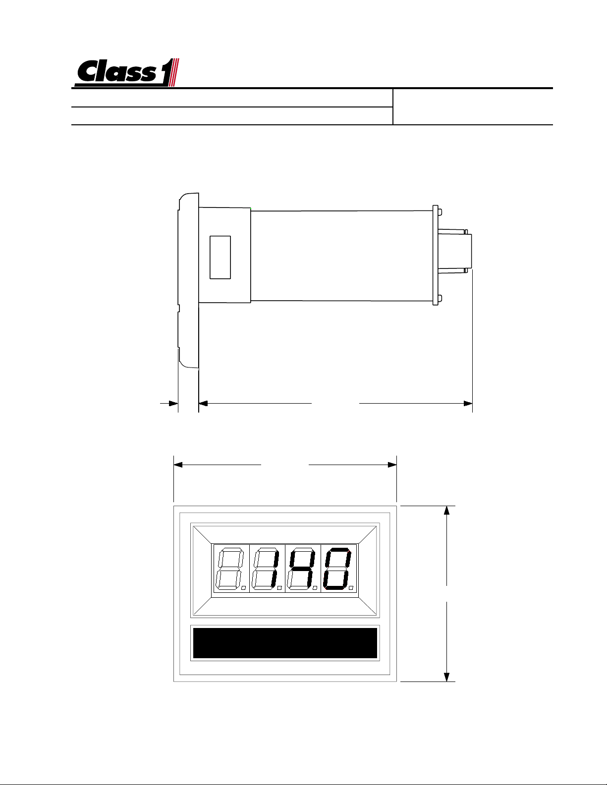
3. Display Installation (cont.)
Engineering Standard Number
C1-102007-A
0.285" 3.832"
3.125"
DIGITAL DISPLAY
2.462"
page 2 of 4 pages
Page 3

Engineering
Standards
Name
Identifier OEM Installation and Calibration
Digital Speedometer Information
4. Electrical
The Speedometer Display is connected to the OEM harness with a Deutsch 8 pin
mini-connector.
Mating Connector: DTM06-08S
Locking Wedge WM-8S
Mating Terminal: 0462-201-20141 20 gauge socket
Terminal Assignments: 1 N/C (no connection)
2 N/C
3 N/C
4 Display Power (Ignition 12 VDC)
5 System Ground
6 N/C
7 Pulses IN (speedometer input)
8 N/C
Engineering Standard Number
C1-102007-A
A usable Pulses In signal is available on the World Transmission wire #157 at the
Vehicle Interface Module connection H-2.
page 3 of 4 pages
Page 4

Engineering
Standards
Name
Identifier OEM Installation and Calibration
Digital Speedometer Information
5. Calibration
Digital Speedometer Calibration is performed with the vehicle speed stabilized at 40
MPH or 40 KPH.
The calibration mode is enabled by the use of a “password”.
Enter the switch sequence below to enter calibration mode.
Left Switch Left Switch Left Switch Right Switch Right Switch Right switch
If the password is correctly entered, “
40 40
by “
40
”.
40 40
Establish a stable vehicle speed of 40. Maintain this speed for a minimum of 15
seconds.
Activate the left switch.
The display will read “
donE donE
donE
donE donE
”
followed by the active speed.
L L L R R R
Cal Cal
Cal
” will be displayed for 1/2 second followed
Cal Cal
Engineering Standard Number
C1-102007-A
Calibration is now complete.
6. Operation
The speedometer will display current vehicle speed whenever the display is enabled
and a valid speedometer signal is received.
Range is from 0 to 120 Miles per Hour (MPH) or Kilometers per Hour (KPH) dependent on the units used for calibration.
SPEEDOMETER
C:\MANUALS\DIGITAL\SPEEDO\SPDO_ESN.P65_121597
page 4 of 4 pages
 Loading...