

Page 1
Engineering
Standards
Mounting
Name
Identifier Instructions
Digital Pressure Gauge
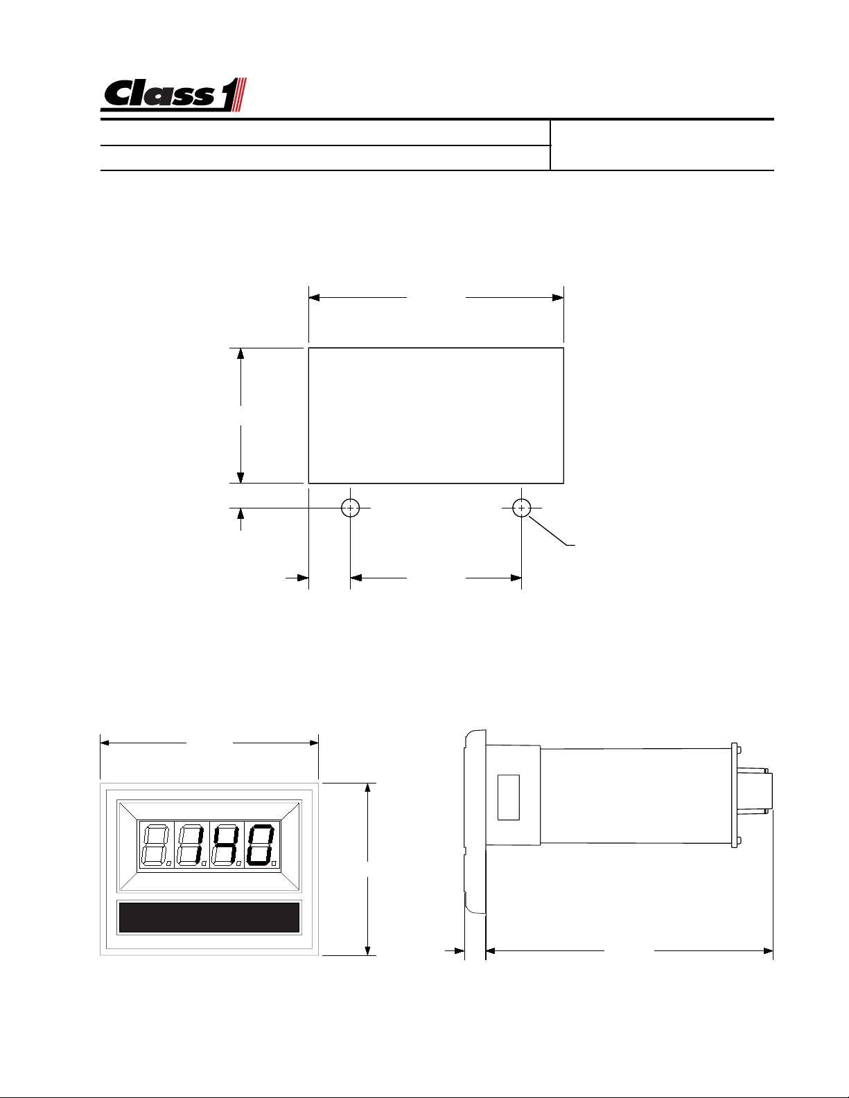
The Class1 digital display mounts in a 2.85” by 1.55” cutout.
Overall area necessary for installation is 2.5” by 3.2”.
T wo 0.20 diameter holes are provided for mounting screws.
1.510
.277
Engineering Standard Number
C1-102190-A
2.840"
3.125"
DIGITAL DISPLAY
Ø 0.201"
(2) HOLES
.470 1.900
2.462"
0.285" 3.832"
page 1 of 6 pages
Page 2
Engineering
Standards
Harness
Name
Identifier Instructions
Digital Pressure Gauge
Engineering Standard Number
C1-102190-A
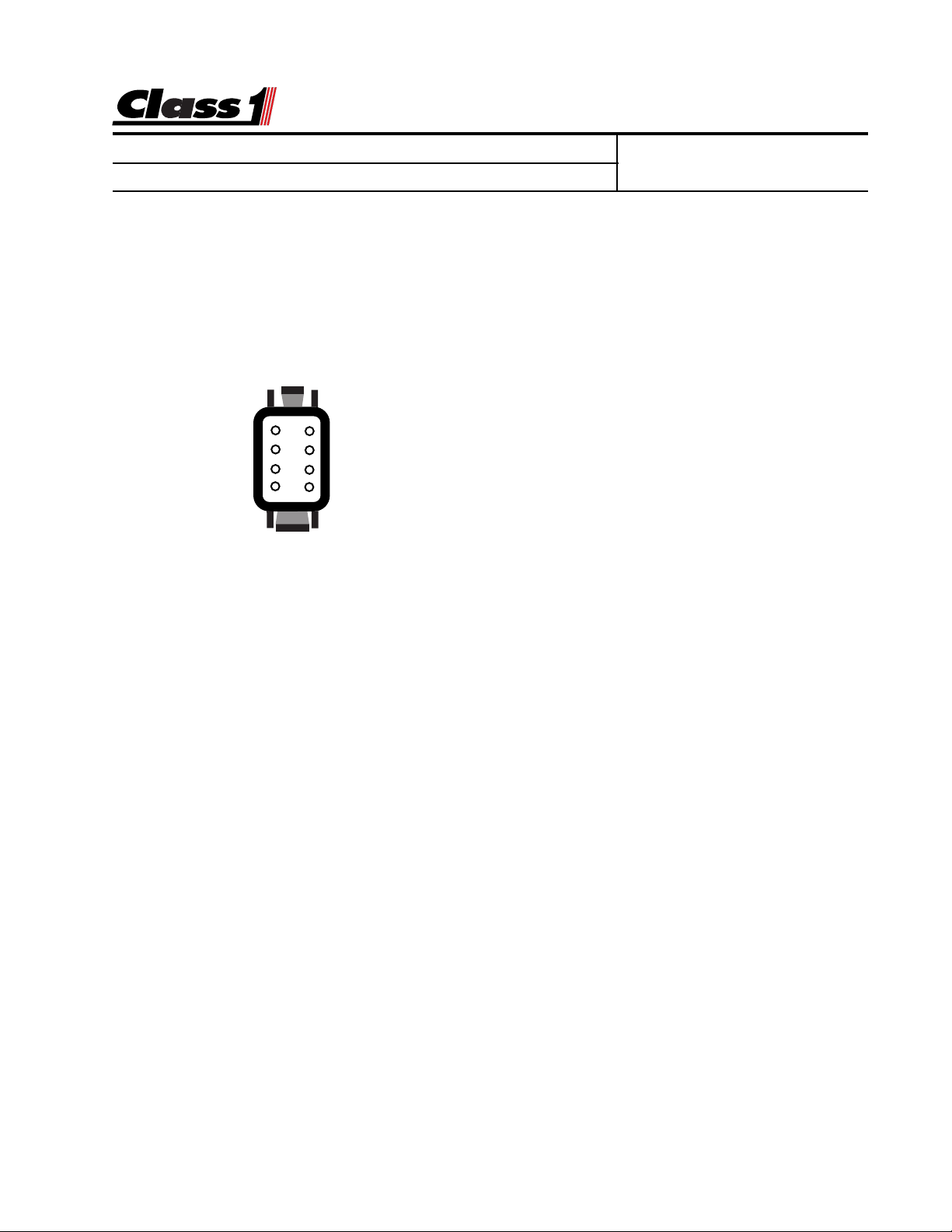
The digital displays are connected to the OEM harness with a Deutsch 8 pin miniconnector .
Mating Connector: DTM06-08S
Locking Wedge WM-8S
Mating T erminal: 0462-201-20141 20 gauge socket
General T erminal Assignments:
1) Alarm Output (Ground)
8
7
6
5
1
2
3
4
2) Primary Pressure Signal
3) Sensor Supply (+ 5 or +10 VDC)
4) Power (+ 12 VDC)
5) Ground
6) Sensor Ground
Wire Insertion View
7) Signal (frequency or secondary PSI in)
8) Test or Total or Alarm
Not all of the digital displays use all of the terminals.
See individual display pages for application information.
Harnesses are available for the digital displays in various lengths.
These include transmitter and power connections.
Harness Part Numbers by length and application.
5’ 10’ 20’ 30’
Flowmeter Display 102064 102033 102065 103165
Pressure Display 102060 102035 102061 102271
Breathing Air Display 102670 102671 102672
Oxygen System Display “ “ “
T ank Level Display 102193 102194 102195 102729
Dual Transducer 102439Y 102455
Speedometer 102242 102243 102244
DC Voltmeter “ “ “
Dual Display “Y” 102294 102295
Dual Current Amplifier 103318
Display Pigtail 102272 Extension 15’ 103367
page 2 of 6 pages
Page 3

Engineering
Standards
Cal. Overview
Name
Identifier Instructions
Digital Pressure Gauge
Engineering Standard Number
C1-102190-A
Location of Magnetic Switches
Digital Display Calibration should be performed to assure accuracy.
Display Calibration sequence for Gauges with 7 segment LED’s
A password will look like the following example.
L L L R R R
Enter the switch sequence with a magnet to enter the basic calibration mode.
Left Switch Left Switch Left Switch Right Switch Right Switch Right Switch
If the password is correctly entered, CAL will be displayed for 1/2 second followed by a number that is dependent on the display being calibrated (usually 0 ). If necessary , the calibration
number can be changed using the switch on the right side.
Establish accurate and stable conditions for calibration.
When the calibration conditions are stable, activate the left switch.
The display will read donE and then return to normal operation.
page 3 of 6 pages
Page 4

Engineering
Standards
Pressure Gauge
Name
Identifier Instructions
Digital Pressure Gauge
Engineering Standard Number
C1-102190-A
Installation and Operation of the Class1 Digital Pressure Gauge.
The pressure transducer (PN 102161) mounts to the pump with a 1/4” NPT fitting. Mount
the pressure transducer on the pump discharge manifold and tighten using the 1-1/4 hex.
Mount the digital display on the pump panel using the dimensions provided.
Connect the wiring harness PN 102035, 102060, or 102061 to the transducer , the display
and to the vehicle power and ground circuits.
8
7
6
5
Wire Insertion View
1
2
3
4
PUMP DISCHARGE
Operation is straightforward.
When the unit is turned on, the display indicates pump pressure at the transducer location. Normally no calibration is required, however if the gauge
does not read zero when the pump is not running, a ZERO calibration can be
performed. Password L R R L L.
This feature is available only on rP1.7 and above.
Harness PN 102060 5’
102035 10’
102061 20’
PIN COLOR FUNCTION
A BLACK SENSOR GROUND
B RED SENSOR SUPPLY
C WHITE SENSOR SIGNAL
Red +12 VDC
Black Ground
PIN COLOR FUNCTION
1 PLUG
2 WHITE SIGNAL
3 RED SENSOR SUPPLY
4 RED POWER IN
5 BLACK GROUND IN
6 BLACK SENSOR GROUND
7 PLUG
8 PLUG
page 4 of 6 pages
Page 5

Engineering
Standards
T-shoot
Name
Identifier Instructions
Digital Pressure Gauge
0462-201-20141 20 Ga.
Switch 8
Pulses IN 7
Sensor Ground 6
System Ground 5
DTM06-08SA
1 N/C
8
7
6
5
Wire Insertion View
1
2
2 PSI IN
3
3 Sensor +5/10 VDC
4
4 System Power
Engineering Standard Number
C1-102190-A
The display does not illuminate.
The display must have power at terminal 4 and ground at terminal 5.
With the connector removed, check across pins 4 and 5 for 12 VDC, if 12 volts is
present with the correct polarity , replace the display . If voltage and/or ground is
not present, check the vehicle wiring.
The pressure reading on a discharge or intake gauge does not change.
There is a problem with the pressure transducer or wiring. At the transducer
connector , check for 5 VDC between pins A (ground) and pin B (+5 VDC). These
are sent from the display and must be of the correct polarity for the transducer to
function. Plug the connector into the transducer and check for voltage at the
display between pin 6 (sensor ground) and pin 2 (signal). With zero pressure/
suction at the pump, this voltage should be between 500 mV and 900 mV . As the
pressure in the pump increases, the voltage should increase. If it does not, then
replace the transducer . If the voltage increases, and the display does not change,
perform a default calibration, call Class1 (1-800-533-3569) for instructions. If the
default calibration does not correct the problem, replace the display .
The pressure display reads SEnS .
There is a problem with the pressure transducer or wiring. At the transducer
connector , check for 5 VDC between pins A (ground) and pin B (+5 VDC). These
are sent from the display and must be of the correct polarity for the transducer to
function. Plug the connector into the transducer and check for voltage between
Pin A (sensor ground) and pin C (sensor signal) at the transducer . With zero
pressure/suction at the pump, this voltage should be between 500 mV and 900
mV , if it is not, replace the transducer . Check for voltage at the display between
pin 6 (sensor ground) and pin 2 (signal). With zero pressure/suction at the pump,
this voltage should be between 500 mV and 900 mV . If it is not, check the wiring
from the transducer to the display . If the correct voltage is present at pin 2,
replace the display .
page 5 of 6 pages
Page 6

Engineering
Standards
T-shoot
Name
Identifier Instructions
Digital Pressure Gauge
Engineering Standard Number
C1-102190-A
The tank level gauge has a bar traveling back and forth across the display .
There is a problem with the pressure transducer (PN 102162) or wiring. At
the transducer connector , check for 5 VDC between pins A (+5 VDC) and pin B
(ground). These are sent from the display and must be of the correct polarity for
the transducer to function. Plug the connector into the transducer and check for
voltage between Pin B (sensor ground) and pin C (sensor signal) at the transducer . With water in the tank, this voltage should be between 500 mV and 900
mV , if it is not, replace the transducer . Check for voltage at the display between
pin 6 (sensor ground) and pin 2 (signal). With an empty tank, this voltage should
be between 500 mV and 900 mV . If it is not, check the wiring from the transducer
to the display . If the correct voltage is present at pin 2, replace the display.
The T ank Level Gauge does not change or calibrate.
There is a problem with the pressure transducer or wiring. At the transducer
connector , check for 5 VDC between pins A (+5 VDC) and pin B (ground). These
are sent from the display and must be of the correct polarity for the transducer to
function. Plug the connector into the transducer and check for voltage at the
display between pin 6 (sensor ground) and pin 2 (signal). With an empty tank, this
voltage should be between 500 mV and 900 mV . As the water level in the tank
increases, the voltage should increase. If it does not, then replace the transducer .
If the voltage increases, and the display does not change, attempt to calibrate
the unit. If the calibration does not correct the problem, replace the display .
The Flow Meter does not read flow or calibrate.
Place the meter in to raw mode L R L R L L. Does the meter read pulses, and do
they change with a flow increase or decrease? If they do, re-calibrate. If you do
not read pulses, then it is a wiring or paddlewheel problem. At the paddlewheel,
check for 12 VDC between pins A (ground) and pin B (+12 VDC). These are sent
from the display and must be of the correct polarity for the paddlewheel to function. Plug the connector into the paddlewheel and check for pulses at the display
between pin 6 (sensor ground) and pin 7 (signal). If pulses are not present, then
check the paddlewheel orientation and the signal wire from the paddlewheel to pin
7 at the display . If everything checks out OK, then replace the paddlewheel. If the
signal is present and the display does not read raw pulses, replace the display .
A-Ground
Pressure Transducer Pinout
B-Supply
C-Signal
page 6 of 6 pages
 Loading...