

Page 1
Engineering
Standards
Name
Identifier Instructions
Digital Oxygen Remaining System
Engineering Standard Number
C1-102264-A
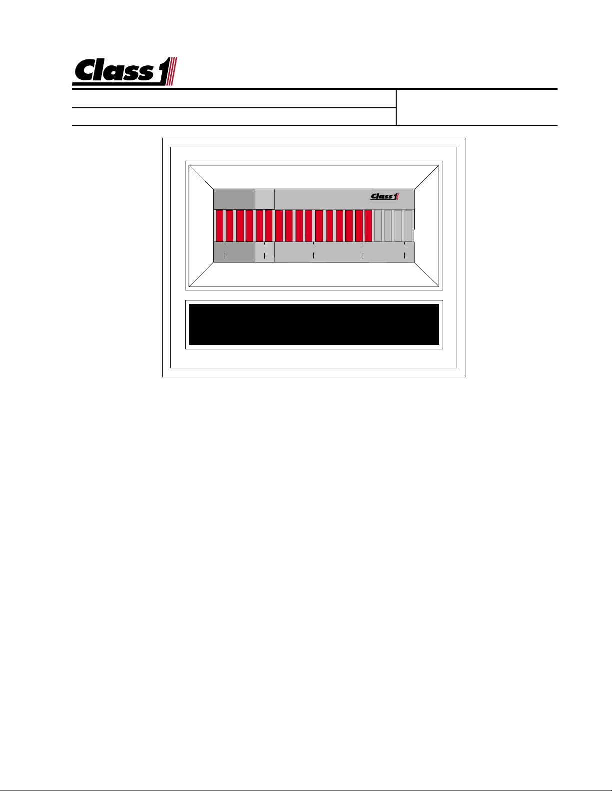
0 25 50 75 100
O2 REMAINING
The
Class1
Oxygen Remaining Display is designed to provide operators with a
visual indication of Oxygen remaining and an audible warning when there is
less than 20% oxygen remaining. The audible warning is inactive whenever the
pressure is below 50 PSI so that it will not sound when the supply is turned off.
The display represents oxygen volume information in an easy to interpret LED
bargraph display as a percentage of maximum calibrated pressure. The display includes a visual warning and an auxiliary warning alarm output.
When the relative volume of oxygen remaining reaches 25%, the bars will begin to flash, and when the system pressure drops to 20%, the auxiliary output
will turn on. The alarm can be silenced with an alarm silence switch. Once the
alarm is silenced, it will remain silent until the unit is turned off and then back on,
and will reset whenever the volume of air exceeds 20%. When the alarm is
silenced, there will be an alert chirp every fifteen (15) minutes to remind the
operator that the oxygen supply is low.
page 1 of 6 pages
Page 2
Engineering
Standards
Name
Identifier Instructions
Digital Oxygen Remaining System
Class1 Class1
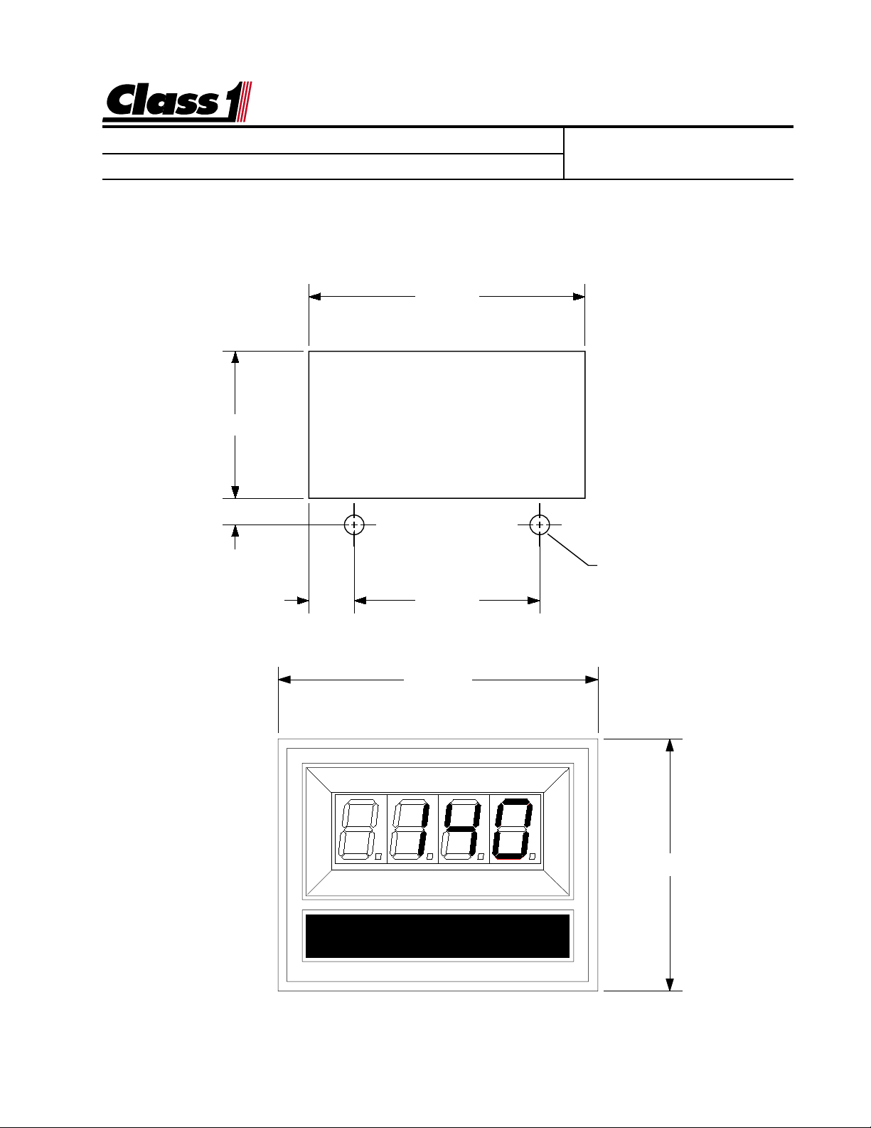
The
Class1 digital displa y mounts in a 2.85” b y 1.55” cutout.
Class1 Class1
Overall area necessary for installation is 2.5” by 3.2”.
Two 0.20 diameter holes are provided f or mounting screws.
1.510
.277
Engineering Standard Number
C1-102264-A
2.840"
.470 1.900
3.125"
DIGITAL DISPLAY
Ø 0.201"
(2) HOLES
2.462"
page 2 of 6 pages
Page 3

Engineering
Standards
Name
Identifier Instructions
Digital Oxygen Remaining System
0.285" 3.832"
Engineering Standard Number
C1-102264-A
Location of magnetic switches
0 25 50 75 100
BAR GRAPH DISPLAY
page 3 of 6 pages
Page 4

Engineering
Standards
Name
Identifier Instructions
Digital Oxygen Remaining System
Engineering Standard Number
C1-102264-A
Display Calibration for Gauges with bargraph displays
The calibration mode is entered by the use of a “password”.
There are two magnetic switches, one located at each side of the display.
These switches are activated with the use of a magnet.
Switch activation is visually confirmed by the toggling of the four closest bars on the display to
the switch. If they are on they will turn off, if they are off they will turn on.
If the password is correctly entered, the leftmost bar will turn on and flash. This indicates that the
display is ready to be calibrated for the low set point.
With the system adjusted to the minimum calibration point (the system should be empty or at the
lowest pressure condition) activate the left switch and then the right switch.
The rightmost bar will begin to flash, indicating the display is ready for the high set point calibration.
Adjust the system to it’s maximum operating condition. Activate the right switch followed by the left
switch.
The display will return to normal operation and indicate current system status as a percentage of
maximum capacity.
Calibration for Breathing Oxygen Gauge installations:
Empty Cylinder (Closed Valve)
With the oxygen bottle closed and the system purged, enter the calibration password.
L L L R R R
The left (0%) bar will flash to indicate that you are ready to calibrate for an empty system.
Activate the left switch followed by the right switch.
The right (100%) bar will flash to indicate that the display is ready to calibrate for a full system.
Maximum Volume
With a full oxygen bottle and the system pressurized, actuate the
right switch and then the left switch.
Calibration is complete.
NOTE: Calibration should be accomplished using an oxygen
cylinder filled to the locally established maximum pressure.
page 4 of 6 pages
Page 5

Engineering
Standards
Name
Identifier Instructions
Digital Oxygen Remaining System
Engineering Standard Number
C1-102264-A
All of the digital displays have a built in lamp test feature.
The password to activate this function is L L R L L.
When activated, all segments on the display LED’s will illuminate for a few
seconds and then return to normal operation.
The digital displays that utilize a pressure sensor have a sensor check feature.
The password to activate this function is L R R L R R.
page 5 of 6 pages
Page 6

Engineering
Standards
Name
Digital Oxygen Remaining System
Identifier Instructions
Wiring Diagram for the Digital Oxygen Remaining Gauge.
DTM06-08SA
0462-201-20141 20 Ga.
1 Alarm OUT (ground)
2 PSI IN (Pressure)
3 Sensor + 10 VDC
4 Power + 12 VDC
5 Ground
6NC
7NC
8 Alarm Silence (ground)
Wire Insertion View
8
7
6
5
1
2
3
4
Alarm OUT
PSI Signal
PSI Supply
BLACK
RED
Engineering Standard Number
C1-102264-A
0.410"
1.425"
Red
Black
Red
1.125"
OEM Power Feed
12 VDC
GroundBlack
CONNECTOR
PIN COLOR
1 RED
2 BLACK
PROVIDED HARNESS
Pressure Transducer
PIN COLOR
1 PLUG
2 BLACK
3 RED
4 RED
5 BLACK
6 PLUG
7 PLUG
8 PLUG
MANUALS\DIGITAL\AIR_LEFT\AM_HARN.AI
manuals\digital\air_level\O2-wire.eps..100998
page 6 of 6 pages
 Loading...