

Page 1
Engineering
Standards
Name
Identifier
Digital Flowmeter Information
Installation and Calibration Information
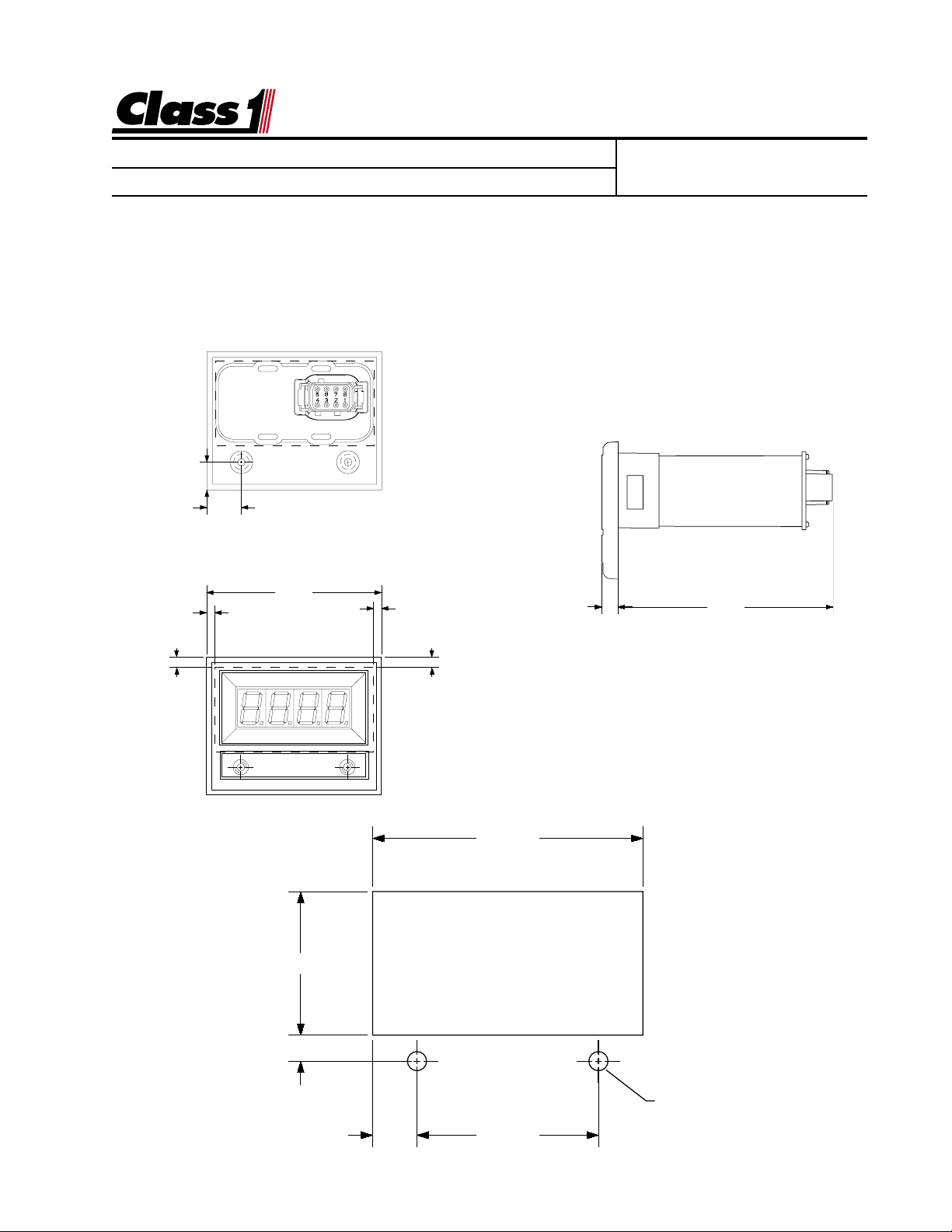
Display Installation
The flowmeter display mounts in a 2.84” by 1.51” cutout.
Overall area necessary for installation is 2.5” by 3.2”.
Two 0.201 diameter holes are provided for mounting scre ws.
0.496"
0.612"
3.125"
0.142"
0.142"
Engineering Standard Number
C1-102046-A
0.285" 3.832"
0.182"0.182"
1.510
.277
2.840"
Ø 0.201"
(2) HOLES
.470 1.900
page 1 of 9 pages
Page 2

Engineering
Standards
Name
Identifier
Digital Flowmeter Information
Saddle Clamp Installation
The Saddle clamp should be mounted on the pump discharge pipe in an area of laminar flow. Select a location with as long a straight run as possible. Avoid mounting
immediately after an elbow, gate or increase in pipe size (Any thing that would cause
turbulence). Allow a straight run of at least 6 pipe diameters after an elbow.
Cut a 1.5” diameter hole in the top side of the waterwa y. Position the saddleclamp
on the pipe with the indexing hole f acing the pump . Tighten the nuts on the “U” bolt
evenly to 30 ft/lbs.
Paddlewheel
Install the paddlewheel adapter (spacer) to the mount using four 7/16” screws.
Lubricate the O-rings on the paddlewheel and insert it into the mount .
Secure the transmitter with the 4 screws provided.
The Class1 Digital Flowmeter measures water velocity in the pipe to calculate the
flow rate. The location of the paddlewheel transmitter is important for proper operation and accurate readings. Mount the transmitter in a location that is accessible for
future maintenance and in an area where laminar (non-turbulent) flow is most likely
to be maintained. Most problems with flowmeter accuracy and performance can be
traced to the location of the transmitter.
The hole size for the paddlewheel transmitter PN102714 mount is 1-1/2”.
Engineering Standard Number
C1-102046-A
Transmitter Location
Elbows/Bends A straight run of pipe to the transmitter of at least six (6) times
the pipe diameter after an elbow or other turbulence producing item is desirable
for a successful installation. Try to locate the transmitter using the longest straight
section of pipe available. Minimal turbulence at the transmitter provides the most
accurate reading.
Valves/Gates If the transmitter is downstream of a valve, the minimum dis tance is
fifteen (15) times the pipe diameter. Whenever possible, mount the transmitter
before a valve.
Horizontal Pipes The transmitter will work in any position, however when mounted
on a horizontal run, it should be mounted in the top half of the pipe to allow debris
to be flushed out of the paddlewheel.
page 2 of 9 pages
Page 3

Engineering
Standards
Name
Identifier
Digital Flowmeter Information
Engineering Standard Number
C1-102046-A
Increase/Decrease in pipe size The transmitter can be placed after an increase in pipe
diameter, never after a decrease.
Class1
flexible hose can greatly assist in reducing the number of elbows and amount of
turbulence between the pump and discharge pipe.
Wiring
The Flowminder system comes with a wiring harness that connects the transmitter
to the display.
The OEM must supply power and ground to the digital display. Consideration
should be given to the conditions under which the display will have power.
The display is internally protected against short circuits, overvoltage and reverse
polarity, but standard installation procedures should provide for circuit protection.
Maximum current used by the flowmeter is 1.5 Amps.
A momentary grounding switch can be added when the totalizer function is desired.
This is connected to the display through the 8 pin mini-connector at pin 8.
Electrical
The Flowmeter Display is connected to the OEM harness with a Deutsch 8 pin
mini-connector.
Mating Connector: DTM06-08S
Locking Wedge WM-8S
Mating Terminal: 0462-201-20141 20 gauge socket
Terminal Assignments: 1 N/C (no connection)
Connection to the vehicle is simply a matter of connecting the RED power wire to a
good 12 VDC voltage source and connecting the BLACK ground wire to a good
system ground.
8
7
6
5
Wire Insertion View
1
2
3
4
2 N/C
3 N/C
4 Display Power (Ignition 12 VDC)
5 System Ground
6 N/C
7 Pulses IN (paddlewheel input)
8 Switch input (Totalizer)
page 3 of 9 pages
Page 4

Engineering
Standards
Name
Identifier
Operation
The flowmeter displays the current flo w rate whenever the displa y has power and
the discharge is open. Range is 0 to 9995 GPM, LPM or IGPM as calibrated.
Totalizer
The display includes a totalizer function that displa ys the total amount of water
that has been flowed since the unit was turned on. This feature is enab led by
grounding terminal number eight (8) of the display connector .
While terminal number 8 is grounded, activating the left switch resets the totalizer
to zero (0).
The totalizer resets to zero whenev er power is remo ved from the displa y.
Multiply the reading on the display b y 100 (add two zeroes) for total flo w .
Digital Flowmeter Information
Engineering Standard Number
C1-102046-A
page 4 of 9 pages
Page 5

Engineering
Standards
Name
Identifier
Digital Flowmeter Information
Installation and Calibration Information
5. Calibration
Flowmeter Calibration is performed with the discharge stabilized at the desired calibration flow. (Smoothbore nozzle and Pitot gauge)
The calibration mode is entered by the use of a “password”.
There are two magnetic switches located at the low er corners of the display.
These switches are activated with the use of a magnet, switch activation is visually
confirmed by the lighting of the closest decimal point on the display.
Enter the switch sequence below to enter calibration mode.
Engineering Standard Number
C1-102046-A
3.125"
2.462"
Location of magnetic switches
Left Switch Left Switch Left Switch Right Switch Right Switch Right switch
If the password is correctly entered, “
0 0
by “
0
”.
0 0
Hold the magnet on the right switch until the display reads the Gallons per Minute
(GPM), Liters per Minute (LPM) or Imperial Gallons per Minute (IGPM) that you are
flowing. The speed with which the display increments/decrements the calibration flow
display increases as the switch is held. If you pass the flow value, release the switch
and reactivate. The display will “reverse direction” each time the switch is activated
and the speed will start out at the slowest rate. Maintain the calibration flow f or a minimum of 10 seconds to assure an accurate and stable calibration before activating the
left switch. When the flow is stable and the calibration flow r ate is entered into the
display, activate the left s witch to complete calibration.
The display will read “
Calibration is now complete.
6. Operation
The Flowminder will display the current flowrate whenever the display is enabled
and the discharge is open. Range is 0 to 9990 GPM, LPM or IGPM.
LEFT LEFT LEFT RIGHT RIGHT RIGHT
Cal Cal
Cal
” will be displayed for 1/2 second followed
Cal Cal
donE donE
donE
donE donE
”
followed by the current flow rate in GPM.
page 5 of 9 pages
Page 6

Engineering
Standards
Name
Identifier
Class1 Class1
The
Class1 digital flowmeter system comes
Class1 Class1
Digital Flowmeter Information
with the digital display, a paddlewheel transmitter and a connecting harness (specify
length). A method of mounting the transmitter to the discharge is needed, call for
options and specify the pipe diameter.
Paddlewheel Installation
Power and Ground
Engineering Standard Number
C1-102046-A
The flow display includes a totalizer function. A momentary switch (optional) is required to operate this feature. The display
will continuously monitor flow when the unit
has power and display the latest total volume when the totalizer switch is pressed.
The total flow is cleared when power is removed from the unit.
FLOW METER
6-32x7/16
Lockwasher
O-ring
6-32x7/16internal hex
Spacer
Indexing Pin
White (Signal)
Black (System Ground)
8
7
6
5
C:\MANUALS\DIGITAL\FMINDER\FMINDSER.PM6_071597
1
DTM06-08S
2
Wire Insertion View
3
4
Red (System Power)
page 6 of 9 pages
Page 7

Engineering
4.380
.683
2.750
.037
R.370
5.000"
3.750"
3.564"
R 1.325"
Standards
Name
Identifier
should be given to cutting out the panel and mounting this system before using the bezel.
The panel cutout is a little more difficult than just mounting a gauge and a display and some planning
A stainless steel bezel is available that can have insets color coded to identify the associated discharge.
Digital Flowmeter Information
information on both flow and pressure for the discharge.
The Value Series flowmeter uses the digital display and a 2-1/2” pressure gauge to give the pump operator
Engineering Standard Number
C1-102046-A
page 7 of 9 pages
Page 8

Engineering
Standards
Name
Identifier
Digital Flowmeter Information
Engineering Standard Number
C1-102046-A
The flowmeter Super System is designed using the digital flowmeter and the digital pressure gauge. Each piece uses the standard digital display cutout. The only additional
consideration from the standard flowmeter is for mounting the pressure transducer. This
should generally be mounted after the valve and is a 1/4 NPT fitting. Use only the 1-1/4”
hex to tighten the transducer, not the body of the sensor. Follow the calibration procedure for pressure and flow as appropriate after installation.
FLOW METER
PUMP DISCHARGE
page 8 of 9 pages
Page 9

Engineering
Standards
Name
Identifier
Digital Flowmeter Information
Engineering Standard Number
C1-102046-A
Enhance your Flowminder Installation
The Digital Flow Display is also available in a plain black wrapper that will
install into an existing conventional Flowminder cutout on the pump panel.
Call
Class1
at 1-800-533-3569 and ask for details.
page 9 of 9 pages
 Loading...