

Page 1

Contents
Table of Contents
Contents................................................................................1
Digital Display s ......................................................................2
Mounting................................................................................3
Harness.................................................................................4
Cal. Overview .................................................................... 5-6
Flowmeter.......................................................................... 7-9
Calibration ...........................................................................10
Example CAL.......................................................................11
V alue Flow...........................................................................1 2
Super Flow ..........................................................................1 3
V ehicle Speed.................................................................14-15
Pressure Gauge ..................................................................16
Aerial Loading.................................................................17-19
Water Le vel.....................................................................20-22
Breathing Air...................................................................23-25
Oxygen Supply ...............................................................26-28
Dual Amplifier ......................................................................29
GPM Flowchart ...................................................................30
IGPM Flowchart ..................................................................31
LPM Flowchart ....................................................................32
Notes...................................................................................33
Troubleshooting ..............................................................34-35
1
Page 2
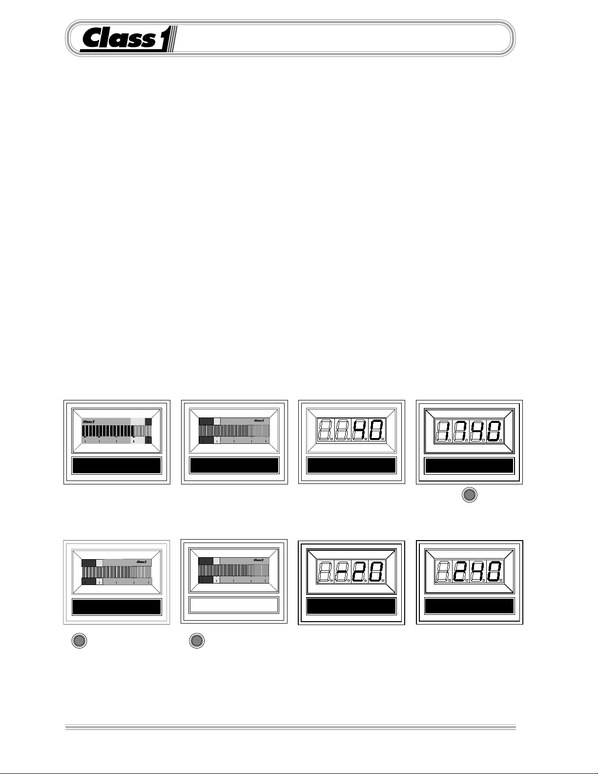
Digital Displays
Class1
’s Digital Gauges.
Digital displays come in both seven (7) segment bright LED displays for alphanumeric
information and bargraph displays f or percentage information.
Currently available displa ys:
102046 Flowmeter
102190 Pump Pressure (Intake and Discharge)
102245 T ank Le vel Gauge (Water and F oam)
102245 Pressurized Tank Level (0 to 100 %)
102007 Speedometer
102342 Aerial Loading
102263 Breathing Air Lev el (0 to 100 %)
102264 Oxygen System Level (0 to 100 %)
103282 Dual Current Amplifier for dual displa ys
(air, O2 and Aerial Loading)
0 25 50 75 100
LOW LEVEL LOADING
0 25 50 75 100
% AIR REMAINING
TEST
ALARM SILENCE
0 25 50 75 100
WATER LEVEL
0 25 50 75 100
% OXYGEN REMAINING
TEST
ALARM SILENCE
SPEEDOMETER
PUMP INTAKE
FLOWMETER
TOTALIZER
PUMP DISCHARGE
2
Page 3
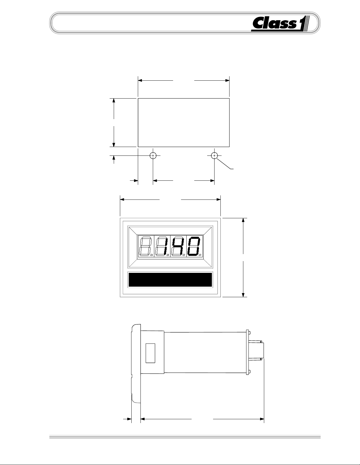
Mounting
The
Class1
Overall area necessary for installation is 2.5” by 3.2”.
Two 0.20 diameter holes are pro vided for mounting screws .
1.510
.277
digital display mounts in a 2.85” by 1.55” cutout.
2.840"
Ø 0.201"
(2) HOLES
.470 1.900
3.125"
DIGITAL DISPLAY
2.462"
0.285" 3.832"
3
Page 4

Harness
The digital displays are connected to the OEM harness with a Deutsch 8 pin miniconnector .
Mating Connector: DTM 06-08S
Locking Wedge WM-8S
Mating T erminal: 0462-201-20141 20 gauge socket
General T erminal Assignments:
1) Alarm Output (Ground)
8
7
6
5
Wire Insertion View
1
2
3
4
2) Primary Pressure Signal
3) Sensor Supply (+ 5 or +10 VDC)
4) System P ower (+ 12 VDC)
5) System Ground
6) Sensor Ground
7) Signal (frequency or secondary PSI in)
8) Test, Total or Alarm Switch (Ground)
Not all of the digital displays use all of the terminals.
See individual display pages for application specific inf ormation.
Harnesses are available for the digital displa ys in v arious lengths.
These include transmitter/transducer and power connections.
Harness Part Numbers by length and application.
5’ 10’ 20’ 30’
Flowmeter Display 102064 102033 102065 103165
Pressure Display 102060 102035 102061 102271
Breathing Air Display 102670 102671 102672
Oxygen System Display “ “ “
Tank Level Display 102193 102194 102195 102729
Dual T ransducer 102439Y 102455
Speedometer 102242 102243 102244
DC Voltmeter “ “ “
Dual Display “Y” 102294 102295
Dual Current Amplifier 103318
Display Pigtail 102272 Extension 15’ 103367
4
Page 5
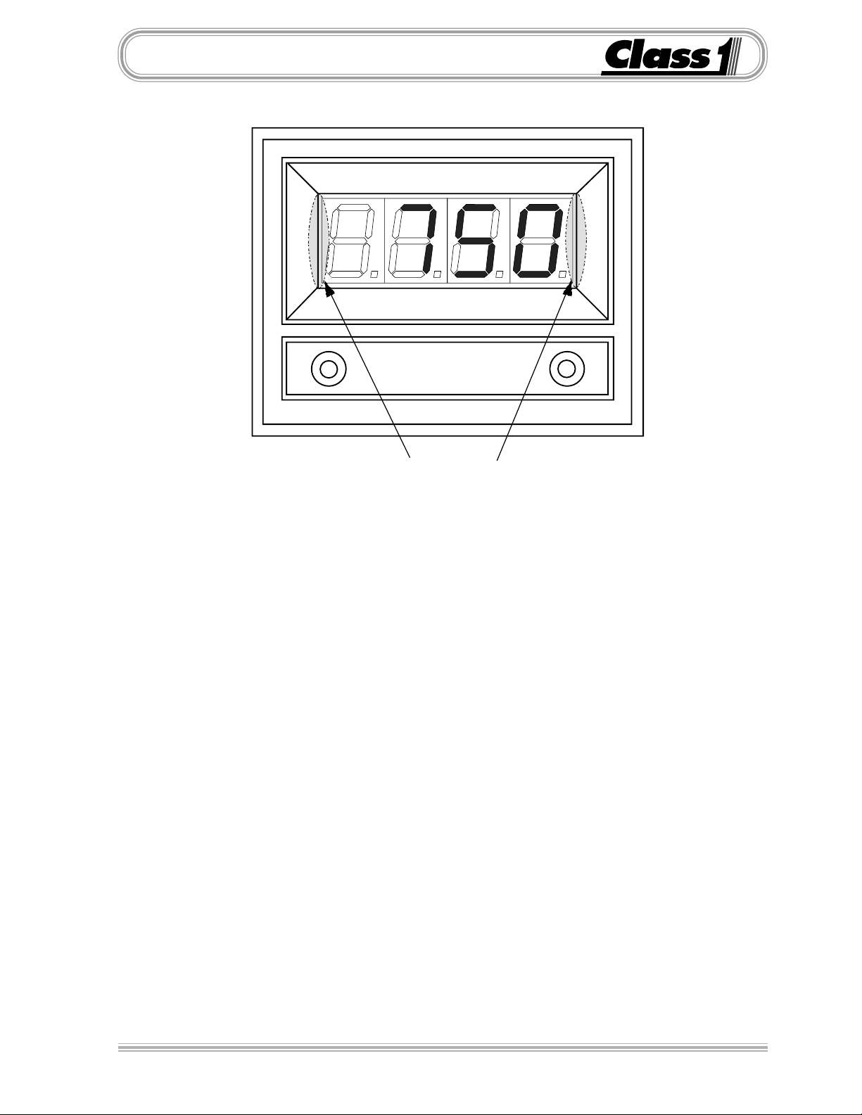
Cal. Overview
Location of Magnetic Switches
Digital Display Calibration should be performed to assure accuracy.
The calibration mode is entered by the use of a “password”.
There are two magnetic switches, one located at each side of the display.
These switches are activated with the use of a magnet.
Switch activation is visually confirmed by the lighting of the closest decimal point on
the display to the switch.
Display Calibration sequence for Gauges with 7 segment LED’s
A password will look like the following example.
L L L R R R
Enter the switch sequence with a magnet to enter the basic calibration mode.
Left Switch Left Switch Left Switch Right Switch Right Switch Right Switch
If the password is correctly entered,
ber that is dependent on the display being calibrated (usually 0 ). If necessary, the calibration
number can be changed using the switch on the right side.
CAL
will be displayed for 1/2 second followed by a num-
Establish accurate and stable conditions f or calibration.
When the calibration conditions are stable, activ ate the left switch.
The display will read
and then return to normal operation.
donE
5
Page 6
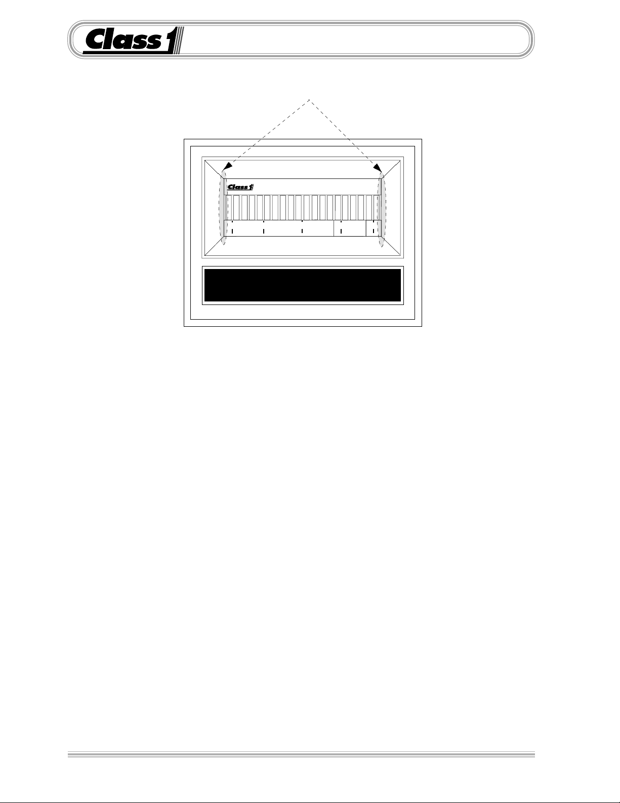
Cal. Overview
Location of magnetic switches
0 25 50 75 100
BAR GRAPH DISPLAY
Display Calibration for Gauges with bargraph displays
The calibration mode is entered by the use of a “password”.
There are two magnetic switches, one located at each side of the display.
These switches are activated with the use of a magnet.
Switch activation is visually confirmed by the toggling of the four closest bars on the
display to the switch. If they are on they will turn off, if they are off they will turn on.
A password will look like the following example.
L L L R R R
Enter the switch sequence with a magnet to enter the basic calibration mode.
Left Switch Left Switch Left Switch Right Switch Right Switch Right Switch
If the password is correctly entered, the left-most bar will turn on and flash. This indicates that
the display is ready to be calibrated for the low set point.
With the system adjusted to the minimum calibration point (the system should be empty or at
the lowest pressure condition) activate the left switch and then the right switch.
The right-most bar will begin to flash, indicating the display is ready for the high set point
calibration.
Adjust the system to it’s maximum operating condition. Activate the right switch followed by
the left switch.
The display will return to normal operation and indicate current system status as a percentage
of maximum calibrated capacity.
6
Page 7
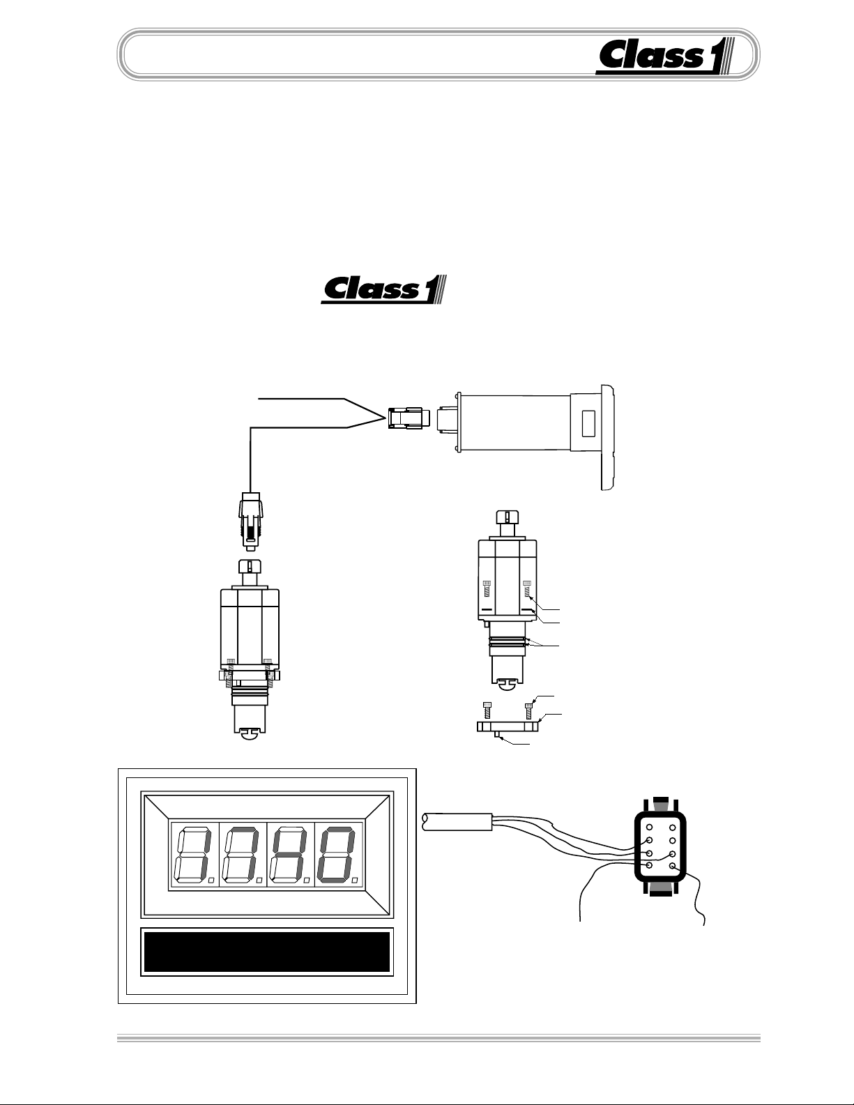
Flowmeter
The
Class1
comes with the digital display, a paddlewheel transmitter and a connecting harness (specify length). Mounting the transmitter to the discharge can be done with a
saddle clamp, a welded boss or a valve
adapter. Call f or options and specify pipe
diameter.
digital flowmeter system
Paddlewheel Installation
The flow display includes a totaliz er function. A momentary switch (optional) is required to operate this feature . The display
will continuously monitor flow when the
unit has power and display the latest total
volume when the totalizer switch is
pressed. The total flow is cleared when
power is removed from the unit.
FLOW METER
6-32x7/16
Lockwasher
O-ring
6-32x7/16internal hex
Spacer
Indexing Pin
White (Signal)
Black (System Ground)
8
7
6
5
1
2
3
4
Red (System Power)
DTM06-08S
Wire Insertion View
7
Page 8

FlowmeterFlowmeter
Flowmeter
FlowmeterFlowmeter
Installation
The
Class1
the flow rate. The location of the paddlewheel transmitter is important for proper
operation and accurate readings. Mount the transmitter in a location that is accessible for future maintenance and in an area where laminar (non-turb ulent) flow is
most likely to be maintained. Most problems with flowmeter accuracy and perf ormance can be traced to the location of the transmitter .
The hole size for the paddlewheel transmitter (PN102714) mount is 1-1/2”.
The hole size for the paddle wheel transmitter (PN101199) mount is 1-7/8”.
T ransmitter Location
Elbows/Bends A straight run of pipe to the transmitter of at least six (6) times
the pipe diameter after an elbow or other turbulence producing item is desirable
for a successful installation. T ry to locate the transmitter using the longest straight
section of pipe available. Minimal turbulence at the transmitter provides the most
accurate reading.
Valves/Gates If the transmitter is downstream of a valve, the minimum distance is fifteen (15) times the pipe diameter. Whenev er possible, mount the
transmitter before a v alve .
Digital Flowmeter measures water velocity in the pipe to calculate
Horizontal Pipes The transmitter will work in any position, howe ver when mounted
on a horizontal run, it should be mounted in the top half of the pipe to allow debris
to be flushed out of the paddlewheel.
Increase/Decrease in pipe size The transmitter can be placed after an increase
in pipe diameter, ne ver after a decrease.
Class1
turbulence between the pump and discharge pipe.
Wiring
The Flowmeter system comes with a wiring harness that connects the transmitter to the display.
The OEM must supply power and ground to the digital displa y . Consideration
should be given to the conditions under which the displa y will have pow er.
The display is internally protected against short circuits, overvoltage and reverse
polarity , but standard installation procedures should provide f or circuit protection.
Maximum current used by the flowmeter is 1.5 Amps.
flexible hose can greatly assist in reducing the number of elbo ws and amount of
A momentary grounding switch can be added when the totalizer function is desired. This is connected to the display through the 8 pin mini-connector at pin 8.
8
Page 9

Operation
The flowmeter displays the current flo w rate whenever the displa y has power and
the discharge is open. Range is 0 to 9995 GPM, LPM or IGPM as calibrated.
Totalizer
The display includes a totalizer function that displa ys the total amount of water
that has been flowed since the unit was turned on. This feature is enabled b y
grounding terminal number eight (8) of the display connector .
When in the totalizer mode, all decimal points will flash to indicate this mode.
While terminal number 8 is grounded, activating the left switch resets the totalizer
to zero (0).
The totalizer resets to zero whene ver pow er is removed from the displa y.
Multiply the reading on the display b y 100 (add two zeroes) for total flow.
FlowmeterFlowmeter
Flowmeter
FlowmeterFlowmeter
9
Page 10

Calibration
Calibration matches the display to the paddlewheel tr ansmitter installation and
signal for a given flo w rate.
A method of accurately determining flow should be used to calibrate the unit.
A smoothbore nozzle and a Pitot gauge is suitable.
Flowmeter calibration must be perf ormed with the discharge flow stabilized at the
desired calibration flow rate.
Establish and maintain the calibration flow rate f or a minimum of 10 seconds to
assure an accurate and stable reading. When the flow is stab le, enter the
flowmeter calibration mode.
The calibration mode passw ord for the flowmeter isL L L R R R.
Switches are located at each side of the display.
These switches are activ ated with the use of a magnet.
Switch activation is visually confirmed by the lighting of the closest decimal point
on the display.
Enter the switch sequence below to enter calibr ation mode.
Calibration
L
eft Left Left Right Right Right
LEFT SWITCH LEFT SWITCH LEFT SWITCH RIGHT SWITCH RIGHT SWITCH RIGHT SWITCH
If the password is correctly entered,
follow ed b y
Using the right switch on the display, enter the flow rate you intend to calibrate. If
the department will use a standard flow for the discharge, use that figure for
calibration.
The speed that the display increments/decrements increases the longer that the
switch is held. If y ou pass the flow calibration n umber , “release” the s witch and
reactivate it. The display will “reverse direction” each time the switch is activ ated
and the speed will start out at the slowest rate.
When the number on the display matches the discharge flo w rate, check the Pitot
for the desired pressure and then activate the left s witch to complete calibration.
The display will read
0
.
donE
and then return to normal operation.
CAL
will be displayed for 1/2 second
10
Calibration is now complete.
Page 11

Example CAL
Example Calibration (4”)
Install a Pitot gauge and a two inch (2”) smoothbore nozzle on the deck gun.
Determine the flow rate that you want to use. (70 PSI=994 GPM).
Start pumping water through the deck gun until the Pitot gauge reads 70 PSI.
Enter the calibration mode by bringing a magnet close to the left side of the display and
removing it three (3) times, the left decimal point should light with each s witch closure.
Bring a magnet close to the right side of the display and remove it three (3) times, the
right decimal point should light with each switch closure.
The display should read
Bring the magnet close to the right side of the display and hold it, the display number
should increase. When the displa y reads
If you stop short of
bring it close again for the display to increase. If you pass
close to the right side and hold it until the number decreases to
994
CAL
for 1/2 second and then
994
, move the magnet aw ay from the displa y .
, you must bring the magnet close to the right side, remove it and
0
994
, just bring the magnet
994
When the flow has been stable at 70 PSI for at least 10 seconds , move the magnet close
to the left side of the display and remov e it.
The display should read
Adjust the flow so that the Pitot reads 50, the display should read
Adjust the flow so that the Pitot reads 110, the display should show
All readings should be within +- 3 % of the 120 PSI value. (+-40 GPM f or a 2” nozzle)
Use a Pitot nozzle flow chart to select a calibration setting. Ideally it should be a v alue
close to the average r ate expected from the discharge.
Check your calibration with flow values that are lower and higher than the calibration
flow but within normal flow rates f or the discharge.
donE
for se veral seconds and then displa y
994
840
1245
Note:
There is a default calibration setting f or 2”, 2.5”, 3”, 4” and 5” schedule 80 pipes.
Pass word to enter default calibration:
L R R R L L L
Scroll through the pipe sizes with the right switch and select with the left switch.
The defaults will only work with schedule 80 pipe.
11
Page 12

Value Flow
4.380
.683
2.750
.037
5.000"
3.750"
3.564"
R 1.325"
should be given to cutting out the panel and mounting this system if you plan to use the bezel.
The panel cutout is a little more difficult than just mounting a gauge and a display and some planning
The Value Series flowmeter uses the digital displa y and a 2-1/2” or 3-1/2” pressure gauge to giv
A stainless steel bezel is available that can have insets color coded to identify the associated discharge.
operator information on both flow and pressure f or the discharge.
e the pump
12
Page 13

Super Flow
The flowmeter Super System is designed using the digital flowmeter and the digital
pressure gauge. Each piece uses the standard digital display cutout. The only additional
consideration from the standard flowmeter is f or mounting the pressure transducer. This
should generally be mounted after the valve and is a 1/4 NPT fitting. Use only the 1-1/4”
hex to tighten the transducer, not the body of the sensor. Follo w the calibration procedure for pressure and flow as appropriate after installation.
FLOW METER
PUMP DISCHARGE
13
Page 14

Vehicle Speed
SPEEDOMETER
The Speedometer Display is connected to the OEM harness with a Deutsch 8 pin
mini-connector.
Mating Connector: DTM06-08S
Locking Wedge WM-8S
Mating T erminal: 0462-201-20141 20 gauge socket
Terminal Assignments: 1 N/C (no connection)
2 N/C
3 N/C
4 Display Power (Ignition 12 VDC)
5 System Ground
6 N/C
7 Pulses IN (speedometer input)
8 N/C
8
7
6
5
Wire Insertion View
1
2
3
4
14
A usable Pulses In signal is available on the World Transmission wire #157 at the
Vehicle Interface Module connection H-2.
Page 15

Vehicle Speed
Calibration
Digital Speedometer calibration is performed with the vehicle speed stabilized at 40 M.P.H.
or (40 K.P.H. )
The calibration mode is entered by the use of a “password”.
There are two magnetic switches, one located at each side of the display.
These switches are activated with the use of a magnet. Switch activation is visually
confirmed by the lighting of the closest decimal point on the display.
Enter the switch sequence below to enter calibration mode.
L L L R R R
Left Switch Left Switch Left Switch Right Switch Right Switch Right Switch
If the password is correctly entered, “
Maintain a constant speed of 40 for a minimum of 10 seconds to assure an accurate and
stable calibration before activating the left switch.
Activate the left switch.
The display will read “
donE
”
and return to normal operation showing the current speed.
CAL
” will be displayed for 1/2 second followed b y
“
40
”
Calibration is now complete.
NOTE:CALIBRATION SHOULD BE PERFORMED BY A PERSON OTHER THAN THE
APPARATUS
DRIVER.
IT IS UNSAFE FOR A DRIVER’S ATTENTION TO BE DIVERTED BY ANY TASK
OTHER
THAN THE SAFE OPERATION OF THE VEHICLE.
15
Page 16

Pressure Gauge
Installation and Operation of the
Class1
Digital Pressure Gauge.
The pressure transducer (PN 102161) mounts to the pump with a 1/4” NPT fitting. Mount
the pressure transducer on the pump discharge manifold and tighten using the 1-1/4 he x.
Mount the digital display on the pump panel using the dimensions provided.
Connect the wiring harness PN 102035, 102060, or 102061 to the transducer, the display
and to the vehicle power and ground circuits.
8
7
6
5
Wire Insertion View
1
2
3
4
PUMP DISCHARGE
Operation is straightforward.
When the unit is turned on, the display indicates pump pressure at the transducer location. Normally no calibration is required, however if the gauge
does not read zero when the pump is not running, a ZERO calibration can be
performed. Password L R R L L.
This feature works only on displays that read rP1.7 and above at power on.
Harness PN 102060 5’
102035 10’
102061 20’
PIN COLOR FUNCTION
A BLACK SENSOR GROUND
B RED SENSOR SUPPLY
C WHITE SENSOR SIGNAL
PIN COLOR FUNCTION
1 PLUG
2 WHITE SIGNAL
3 RED SENSOR SUPPLY
4 RED POWER IN
5 BLACK GROUND IN
6 BLACK SENSOR GROUND
7 PLUG
8 PLUG
Red +12 VDC
Black Ground
16
Page 17

Aerial Loading
0 25 50 75 100
LOW LEVEL LOADING
The
Class1
dangerous loading conditions when an aerial device is operated at low angles
of elevation. Live loads (factors that increase this load such as ice, occupants on the ladder, water load, extra equipment, etc.) are instantly taken into
account by the system and displayed to the operator.
The display presents load information in an easy to interpret LED bargraph
display as a percentage of maximum calibrated load and includes visual and
aural warnings.
When the aerial load approaches the maximum load (approx. 80%), 18-20
bars will be illuminated on the display. When the load is increased to 90%100%, the display will begin to flash, when the maximum load is exceeded by
50-100 pounds, an audible alarm output is activated in addition to the visual
warning to notify the operator of a potentially hazardous condition.
Aerial Loading Display is designed to warn aerial operators of
NOTE: THE DISPLAY PROVIDES A WARNING ONLY AND CANNO T
PREVENT
A TIP-OVER. THE AERIAL DEVICE MUST BE OPERA TED
STRICT ACCORDANCE WITH THE MANUFACTURER’S INSTRUC-
IN
TIONS AND OPERATORS MUST BE THOROUGHLY TRAINED.
17
Page 18

Single transducer installation:
The transducer (PN 102606) must be installed in the pressure feed line to the
actuating cylinder(s) or where it can sense the hydraulic pressure necessary to
lift the aerial device.
Supply 12 VDC and ground to the displa y .
Route the transducer wiring from the display to the transducer and plug in the
connector .
If an audible alarm is desired, connect the alarm output (ground) from terminal #1
of the 8 pin display connector to the ground side of the alarm. An alarm test
switch may be connected from ground to terminal #8 of the display connector .
Dual transducer installation:
Identical to a single transducer installation with the addition of a second transducer that should be installed on the rod side of the hydraulic actuator . This
transducer signal is read at terminal #7 of the display connector .
12 VDC
P.N.1800060
Display Power
Alarm Output (Ground)
Aerial Loading
PIN COLOR FUNCTION
1 OEM Alarm OUT (ground)
2 WHITE PRIMARY SIGNAL
3 RED SENSOR SUPPLY
4 RED POWER IN
5 BLACK GROUND IN
6 BLACK NC
7 WHITE SEC. SIGNAL (opt.)
8 OEM Alarm Test (ground)
Primary (barrel) Transducer Cable
Secondary (rod) Transducer Cable (OPTIONAL)
Display Ground
Alarm Test
WIRE COLOR FUNCTION
1 RED SENSOR SUPPLY
2 WHITE SENSOR SIGNAL
The Aerial Loading Display is connected to the OEM harness with a Deutsch 8 pin miniconnector.
Mating Connector: DTM06-08S
Locking Wedge WM-8S
Mating T erminal: 0462-201-20141 20 gauge socket
Terminal Assignments: 1 Alarm OUT (ground)
2 Pressure Signal IN (4-20 mA)
3 10 VDC OUT
4 Display Power (Ignition 12 VDC)
5 System Ground
6 Sensor Ground OUT
7 Rod pressure IN (Dual Transducer 4-20 mA)
8 Alarm Test IN (ground)
18
Page 19

Aerial Loading
WARNING:
CALIBRATION SHOULD ONLY BE PERFORMED BY THE
AERIAL
MANUFACTURER!
IF YOU FEEL THAT THE DISPLAY NEEDS CALIBRATION, CONTACT YOUR
AERIAL
Aerial manufacturers must ensure that the lift cylinder(s) do not bottom out
during operations. This would cause an erroneous hydraulic pressure reading and the warning system will not operate as designed.
The
Class1
ever two displays are operated from one current transducer (aerial loading, air pressure and oxygen gauges)
Dual Current Amplifier (PN 103282) should be used when-
MANUFA CTURER.
Dual Displays
.
A harness is available to simplify the installation (PN 103283)
19
Page 20

Tank Level
Tank Level Gauge
Transducer Installation
FLUID TANK
3/4 NPT Elbow (OEM)
The transducer must be mounted vertically as depicted to insure an accurate and reliable reading.
This will also prevent damage to the transducer from freezing.
Harness
102193 5'
102194 10'
102195 20'
Pressure Transducer
1/4 NPT
Adapter 3/4-1/4 NPT Bushing (OEM)
Foam adapter is supplied when a
foam level system is ordered.
The tank level gauge transducer should be mounted near the bottom of the
tank. (Approximately two (2) inches off the bottom)
The display, the transducer and the har ness are supplied to ease installation.
When ordered for foam, a special baffled adapter is included with the installation kit.
0 25 50 75 100
TANK LEVEL
20
Page 21

Tank Level
The Tank Level Display is connected to the OEM harness with a Deutsch 8
pin connector.
Mating Connector: DTM06-08S
Locking Wedge WM-8S
Mating Terminal: 0462-201-20141 (20 gauge socket)
Terminal Assignments: 1 Alarm OUT
2 Pressure Signal IN
3 5 VDC OUT
4 Display Power (Ignition 12 VDC)
5 System Ground
6 Sensor Ground OUT
7 Secondary pressure IN ( option )
8 Alarm Silence IN
Mount a 3/4 NPT elbow just off the bottom of the tank, enough to keep sediment out of the elbow and transducer (PN 102162). Attach a 3/4 to 1/4 NPT
adapter (supplied for foam) to the elbow and mount the transducer to that.
The elbow and adapter need to be installed so that the transducer is mounted
vertically.
Pressurized Tanks
If you have a pressurized tank, two pressure transducers (PN 102162) can
be used to compensate for pressure or vacuum in the tank. One transducer
should be mounted near the bottom of the tank and one near the top.
When calibrating the dual transducer installation, the tank should
be vented to the atmosphere .
21
Page 22

Tank Level
Basic Calibration: (2 point)
With the fluid tank empty, enter the
calibration password.
L L L R R R
The left (0%) bar will flash to indicate that you are ready to calibrate
for an empty tank.
Activate the left switch followed by
the right switch.
The right (100%) bar will flash to
indicate that the display is ready to
calculate for a full tank.
When the tank is full, actuate the
right and then the left switch.
Advanced Calibration: (5 point)
With the fluid tank empty, enter the
calibration password.
L L R R L L
The left (0%) bar will flash to indicate that you are ready to calibrate
empty.
Activate the left switch followed by
the right switch.
The fifth bar from the left (25%) will
flash to indicate that the display is
ready to calculate for a quarter tank.
Fill the tank to 1/4 full, actuate the
right and then the left switch.
Calibration is complete.
If after checking the accuracy of
your calibration, you are not satisfied, you can perf orm the adv anced
calibration procedure. This is rarely
necessary except in the case of
oddly shaped tanks.
The tenth bar from the left (50%)
will flash to indicate that the display
is ready to calculate for a half tank.
Fill the tank to 1/2 full, actuate the
left and then the right switch.
The fifteenth bar from the left (75%)
will flash to indicate that the display
is ready to calculate for three f ourths
tank.
Fill the tank 3/4 full, actuate the right
and then the left switch.
The right (100%) bar will flash to
indicate that the display is ready to
calculate for a full tank.
When the tank is full, actuate the
right and then the left switch.
22
Calibration is complete.
Page 23

Breathing Air
0 25 50 75 100
BREATHING AIR
The
Class1
visible indication of breathing air remaining and an audible warning when
there is less than 20% air remaining. The alarm will not activate when there is
less than 50 PSI air in the system, this silences the alarm when the air supply
is turned off.
The display represents air volume information in an easy to interpret LED
bargraph display as a percentage of maximum calibrated pressure. The
Breathing Air Display includes a visual warning and an auxiliary warning alar m
output.
When the relative volume of air remaining reaches 25%, the bars will begin to
flash and the alarm output will becomes active when system pressure drops
to 20%. The alarm can be silenced with an alarm silence switch. Once the
alarm is silenced, it will remain silent for five (5) minutes or until the unit is
turned off and then back on, and is reset whenever the volume of air exceeds
20%.
Breathing Air Display is designed to provide firefighters with a
23
Page 24

DTM06-08SA
0462-201-20141 20 Ga.
1 Alarm OUT (ground)
2 PSI IN (Pressure)
3 Sensor + 10 VDC
4 Power + 12 VDC
5 Ground
6NC
7NC
8 Alarm Silence (ground)
Wire Insertion View
8
7
6
5
1
2
3
4
Alarm OUT
PSI Supply
PSI Signal
BLACK
Breathing Air
0.410"
RED
Red
Black
Black
Red
1.125"
1.425"
OEM Power Feed
12 VDC
Ground
CONNECTOR
Pressure Transducer
PIN COLOR
1 PLUG
2BLACK
3 RED
4 RED
5BLACK
6 PLUG
7 PLUG
8 PLUG
MANUALS\DIGITAL\AIR_LEFT\AM_HARN.AI
The
PIN COLOR
1 RED
2 BLACK
Class1
PROVIDED HARNESS
manuals\digital\air_level\AM-wire.eps..100998
breathing air gauge is easily wired into the apparatus using the supplied
installation kit that includes the necessary wiring harness and connectors.
24
Page 25

Breathing Air
Calibration for Breathing Air Gauge installations:
Empty Cylinder (Closed Valve)
With the air bottle closed and the system purged, enter
the calibration password.
L L L R R R
The left (0%) bar will flash to indicate that you are ready to calibrate for an
empty system.
Activate the left switch followed by the right switch.
The right (100%) bar will flash to indicate that the display is ready to calibrate
for a full system.
Maximum Air
With a full air bottle and the valve open actuate the right switch
and then the left switch.
Calibration is complete.
Calibration should be accomplished using an air cylinder filled to the locally
established maximum pressure.
Dual Displays
The
Class1
are operated from one current transducer (aerial loading, air pressure and oxygen gauges).
A harness is available to simplify the installation (PN 103283)
Dual Current Amplifier (PN 103282) should be used whenever tw o displays
25
Page 26

Oxygen Supply
0 25 50 75 100
O2 REMAINING
The
Class1
a visible indication of Oxygen remaining and an audible warning when there
is less than 20% oxygen remaining. The audible warning is inactive whenever the pressure is below 50 PSI so that it will not sound when the supply is
turned off.
The display represents oxygen volume information in an easy to interpret
LED bargraph display as a percentage of maximum calibrated pressure. The
display includes a visual warning and an auxiliary warning alarm output.
When the relative volume of oxygen remaining reaches 25%, the bars will
begin to flash, and when the system pressure drops to 20%, the auxiliary
output will turn on. The alarm can be silenced with an alarm silence switch.
Once the alarm is silenced, it will remain silent until the unit is turned off and
then back on, and will reset whenever the volume of air exceeds 20%. When
the alarm is silenced, there will be an aler t chirp every fifteen (15) minutes to
remind the operator that the oxygen supply is low.
Oxygen Remaining Display is designed to provide operators with
26
Page 27

Oxygen Supply
DTM06-08SA
0462-201-20141 20 Ga.
1 Alarm OUT (ground)
2 PSI IN (Pressure)
3 Sensor + 10 VDC
4 Power + 12 VDC
5 Ground
6NC
7NC
8 Alarm Silence (ground)
Wire Insertion View
8
7
6
5
1
2
3
4
Alarm OUT
PSI Signal
PSI Supply
BLACK
RED
Red
0.410"
1.125"
1.425"
OEM Power Feed
12 VDC
GroundBlack
Black
Red
CONNECTOR
PIN COLOR
1 RED
2 BLACK
PROVIDED HARNESS
Pressure Transducer
PIN COLOR
1 PLUG
2 BLACK
3 RED
4 RED
5 BLACK
6 PLUG
7 PLUG
8 PLUG
MANUALS\DIGITAL\AIR_LEFT\AM_HARN.AI
manuals\digital\air_level\O2-wire.eps..100998
27
Page 28

Oxygen Supply
Calibration for Breathing Oxygen Gauge installations:
Empty Cylinder (Closed Valve)
With the oxygen bottle closed and the system purged, enter
the calibration password.
L L L R R R
The left (0%) bar will flash to indicate that you are ready to calibrate for an
empty system.
Activate the left switch followed by the right switch.
The right (100%) bar will flash to indicate that the display is ready to calibrate
for a full system.
Maximum Volume
With a full oxygen bottle and the system pressurized, actuate the
right switch and then the left switch.
NOTE:
Calibration is complete.
Calibration should be accomplished using an oxygen
cylinder filled to the locally established maximum pressure.
28
Page 29

PRIMARY DISPLAY
PIN COLOR CIRCUIT
1 OEM Alarm
2 BLACK Signal
3 RED 10 VDC
4 RED V IGN
5 BLACK GND
6 Black Sensor 7 PLUG --8 OEM Silence
DUAL OUTPUT CONVERTER
PIN COLOR CIRCUIT
1 BLACK SIGNAL 1
2 WHITE SIGNAL 2
3 BLACK XDucer IN
4 RED V IGN
5 BLACK GND
6 PLUG --
Ignition
2.5'
2.5'
Ground
5'
2.5'
7 RED T V+
8 PLUG --
Dual Amplifier
PIN COLOR CIRCUIT
1 RED 10 VDC
2 BLACK SIGNAL
PIN COLOR CIRCUIT
1 OEM Alarm
2 White Signal
3 PLUG --4 RED V IGN
5 BLACK GND
6 PLUG --7 PLUG --8 OEM Silence
SENSOR
Secondary DISPLAY
10'
DISPLAY 2 Signal Wire
Turntable
or
Reel
12"
12"
A Dual Current Amplifier should be used whenever two displays share a single 4-20 mA transducer.
29
Page 30

30
PIPE 3/4 2 2-1/2 3 3-1/2 4 5 6 12
Pitot PSI U.S. Gallons per Minute at various nozzle sizes approx
Pressure 1/2" 5/8" 3/4" 7/8" 1" 1-1/8" 1-1/4" 1-3/8" 1-1/2" 1-5/8" 1-3/4" 1-7/8" 2" 2-1/4" 2-1/2" 3" 6"
30 41 64 92 125 163 206 254 308 366 430 498 57 2 651 824 1017 1464 5856
35 44 69 99 135 176 222 275 332 395 464 538 61 8 703 890 1098 1581 6324
40 47 73 106 144 188 238 294 355 423 4 96 575 660 75 1 951 1174 1691 6764
45 50 78 112 153 199 252 311 377 448 5 25 610 700 79 7 1009 1245 1793 7172
50 53 82 118 161 210 266 328 397 473 5 55 643 738 84 0 1063 1313 1890 7560
55 55 86 124 169 220 279 344 417 496 5 82 675 774 88 1 1115 1377 1982 7928
60 58 90 130 176 230 291 360 435 518 6 08 705 809 92 0 1165 1438 2071 8284
62 58 91 132 179 234 296 366 442 526 6 18 716 822 93 5 1184 1462 2105 8420
64 59 93 134 182 238 301 371 449 535 6 28 728 835 95 0 1203 1485 2138 8552
66 60 94 136 185 241 305 377 456 543 6 37 739 848 96 5 1222 1508 2172 8688
68 61 96 138 188 245 310 383 463 551 6 47 750 861 98 0 1240 1531 2204 8816
70 62 97 140 190 248 315 388 470 559 6 56 761 874 99 4 1258 1553 2236 8944
72 63 99 142 193 252 319 394 477 567 6 66 772 886 1008 1276 1575 2268 9072
74 64 100 144 196 255 323 399 483 575 675 78 3 898 1022 1293 1597 2299 9196
76 65 101 146 198 259 328 405 490 583 684 79 3 910 1036 1311 1618 2330 9320
78 66 103 148 201 262 332 410 496 590 693 80 3 922 1049 1328 1639 2361 9444
80 66 104 150 203 266 336 415 502 598 702 81 4 934 1063 1345 1660 2391 9564
85 68 107 154 210 274 347 428 518 616 723 83 9 963 1095 1386 1711 2465 9860
90 70 110 159 216 282 357 440 533 634 744 863 991 1127 1427 1761 2536 10144
95 72 113 163 222 289 366 452 547 651 765 887 1018 1158 1466 1809 2605 10420
100 74 116 167 228 297 376 464 562 668 784 910 1044 1188 1504 1856 2673 10692
105 76 119 171 233 304 385 476 575 685 804 932 1070 1217 1541 1902 2739 10956
110 78 122 175 239 311 394 487 589 701 823 954 1095 1246 1577 1947 2803 11212
115 80 125 179 244 319 403 498 602 717 841 976 1120 1274 1613 1991 2867 11468
120 81 127 183 249 325 412 509 615 732 859 997 1144 1301 1647 2034 2928 11712
GPM Flowchart
Page 31

Flow Calibration Chart
PIPE 3/4 2 2-1/2 3 3-1/2 45612
Pitot PSI Imperial Gallons per Minute at various nozzle sizes approx
Pressure
30 3 4 53 77 104 136 172 211 256 305 358 415 476 542 686 847 1219 4876
35 3 7 57 82 112 147 185 229 276 329 386 448 515 585 741 914 1316 5266
40 3 9 61 88 120 157 198 245 296 352 413 479 550 625 792 978 1408 5632
45 4 2 65 93 127 166 210 259 314 373 437 508 583 664 840 1037 1493 5972
50 4 4 68 98 134 175 221 273 331 394 462 535 615 699 885 1093 1574 6295
55 4 6 72 103 141 183 232 286 347 413 485 562 644 734 928 1147 1650 6601
60 4 8 75 108 147 192 242 300 362 431 506 587 674 766 970 1197 1724 6898
62 4 8 76 110 149 195 246 305 368 438 515 596 684 779 986 1217 1753 7011
64 4 9 77 112 152 198 251 309 374 445 523 606 695 791 1002 1237 1780 7121
66 5 0 78 113 154 201 254 314 380 452 530 615 706 804 1018 1256 1809 7234
68 5 1 80 115 157 204 258 319 386 459 539 625 717 816 1033 1275 1835 7341
70 5 2 81 117 158 207 262 323 391 465 546 634 728 828 1047 1293 1862 7447
72 5 2 82 118 161 210 266 328 397 472 555 643 738 839 1062 1311 1888 7554
80 5 5 87 125 169 221 280 346 418 498 585 678 778 885 1120 1382 1991 7964
85 5 7 89 128 175 228 289 356 431 513 602 699 802 912 1154 1425 2053 8210
90 5 8 92 132 180 235 297 366 444 528 620 719 825 938 1188 1466 2112 8447
95 6 0 94 136 185 241 305 376 455 542 637 739 848 964 1221 1506 2169 8676
100 62 97 1 39 190 247 313 386 468 556 653 758 869 989 1252 1545 2226 8903
105 63 99 1 42 194 253 321 396 479 570 669 776 891 1013 1283 1584 2281 9123
110 65 102 146 199 259 328 406 490 584 685 794 912 1038 1313 1621 2334 9336
115 67 104 149 203 266 336 415 501 597 700 813 933 1061 1343 1658 2387 9549
120 67 106 152 207 271 343 424 512 610 715 830 953 1083 1371 1694 2438 9752
1/2" 5/8" 3/4" 7/8" 1" 1-1/8" 1-1/4" 1-3/8" 1-1/2" 1-5/8" 1-3/4" 1-7/8" 2" 2-1/4" 2-1/2" 3" 6"
IGPM Flowchart
IGPM FlowchartIGPM Flowchart
IGPM FlowchartIGPM Flowchart
31
Page 32

LPM Flowchart
Flow Calibration Chart
PIPE
Pitot Kpa Liters per Minute at various nozzle sizes
Pressure
140 2014 2551
150 2108 2676
170 2203 2797
180 2294 291 1
190 2381 3025
210 2464 3127
220 2548 3233
230 2623 3331
250 2699 3426
260 2775 3520
280 401 628 708 897 1113 1597 2177 2502 2847 3611
290 413 643 727 920 1 139 1635 2230 2562 2915 3702
300 420 659 742 939 1 166 1673 2283 2623 2983 3785
320 432 674 757 961 1 192 171 1 2336 2684 3051 3865
330 439 685 776 980 1219 1749 2385 2740 3119 3948
350 447 708 791 1003 1 1257 1787 2434 2824 3184 4031
360 458 716 806 1022 1268 1821 2483 2850 3244 4115
370 466 727 821 1041 1294 1855 2529 2907 3305 4194
390 473 742 837 1060 1317 1889 2574 2960 3365 4274
400 485 753 852 1079 1340 1923 2620 3013 3426 4349
420 492 774 867 1098 1374 1957 2665 3089 3483 4418
430 500 780 882 1117 1385 1987 2710 31 15 3543 4493
440 507 791 897 1 132 1408 2018 2752 3164 3600 4565
450 515 799 908 1 151 1419 2052 2794 3189 3653 4633
470 522 818 924 1 166 1450 2082 2839 3263 3710 4701
480 530 829 935 1 185 1472 21 12 2881 3308 3763 4770
500 538 840 950 1204 1491 2143 2919 3354 3816 4838
510 545 852 961 1219 1514 2173 2960 3403 3872 4900
530 553 869 977 1234 1542 2203 2996 3471 3922 4970
540 560 874 988 1249 1552 2230 3040 3494 3975 5035
550 568 886 999 1268 1575 2256 3078 3535 4024 5099
570 575 897 1014 1283 1593 2286 31 15 3581 4073 5163
580 583 908 1026 1298 1612 2313 3153 3622 4122 5224
590 587 920 1037 1314 1631 2339 3191 3668 4172 5284
610 594 927 1049 1329 1650 2370 3229 3709 4221 5345
620 602 939 1060 1344 1669 2396 3263 3751 4270 5409
640 609 956 1071 1359 1696 2423 3301 3813 4315 5470
650 613 961 1083 1374 1703 2449 3335 3834 4361 5527
660 621 969 1094 1389 1722 2476 3369 3876 4406 5587
680 628 980 1105 1401 1741 2496 3407 3914 4452 5644
690 636 992 11 17 1416 1760 2525 3441 3955 4501 5701
730 651 1020 1147 1450 1812 2585 3528 4075 4611 5837
760 666 1037 1173 1484 1843 2646 3611 4148 4720 5977
790 681 1060 1200 1518 1885 2707 3770 4239 4826 6113
830 693 1083 1226 1552 1927 2763 3891 4330 4932 6242
19mm23.8mm 25.4mm 28.5mm 31.8mm 38.1mm 44.5mm 47.6mm 50.8mm 57.2mm
32
Page 33

Notes
All of the digital displays have a built in lamp test feature. The password to
activate this function is:
L L R L L.
When activated, all segments on the display LED’s will illuminate for a few
seconds and then return to normal operation.
The digital displays that utilize a pressure sensor have a sensor check feature. The password to activate this function is:
L R R L R R.
Special Function Passwords:
Transducer Status Check:
L R R L R R
Pressure Gauge:
Zero Calibration to match transducer to display:
Used if the gauge indicates pressure or vacuum erroneously.
Flowmeter:
Display Raw Pulses:
Checks paddlewheel operation.
Noise cancellation:
Cancels out flow indication from eddy currents on a transmitter when
the discharge valve is closed. Toggles
Reset Totalizer :
rP1.7 or above
L R L R R R R L
L R R L L
L R L R L L
C on
L
or
C off.
This password will only work when the flowmeter is in totalizer mode.
33
Page 34

0462-201-20141 20 Ga.
(ground) Switch 8
Pulses IN 7
Sensor Ground 6
System Ground 5
The display does not illuminate.
The display must hav e power at terminal 4 and ground at terminal 5.
With the connector removed, chec k across pins 4 and 5 for 12 VDC , if 12 volts is
present with the correct polarity , replace the displa y. If v oltage and/or ground is
not present, check the vehicle wiring and display harness terminations.
DTM06-08SA
1 Alarm OUT (grund)
8
7
6
5
Wire Insertion View
1
2
2 PSI IN
3
3 Sensor +5/10 VDC
4
4 System Power
T-shoot
The pressure reading on a discharge or intake gauge does not change.
There is a problem with the pressure transducer or wiring. At the transducer
connector, chec k for 5 VDC between pins A (ground) and pin B (+5 VDC). These
are sent from the display and m ust be of the correct polarity for the transducer to
function. Plug the connector into the transducer and check f or v oltage at the
display between pin 6 (sensor g round) and pin 2 (signal). With zero pressure/
suction at the pump, this v oltage should be between 500 mV and 900 mV. As the
pressure in the pump increases, the voltage should increase. If it does not, then
replace the transducer . If the v oltage increases, and the display does not change,
perform a default calibration, call Class1 (1-800-533-3569) f or instructions. If the
default calibration does not correct the problem, replace the displa y .
The pressure display reads
SEnS
.
There is a problem with the pressure transducer or wiring. At the transducer
connector, chec k for 5 VDC between pins A (ground) and pin B (+5 VDC). These
are sent from the display and m ust be of the correct polarity for the transducer to
function. Plug the connector into the transducer and check f or voltage between
Pin A (sensor ground) and pin C (sensor signal) at the transducer . With zero
pressure/suction at the pump, this v oltage should be between 500 mV and 900
mV, if it is not, replace the transducer. Check f or v oltage at the display betw een
pin 6 (sensor ground) and pin 2 (signal). With zero pressure/suction at the pump ,
this voltage should be between 500 mV and 900 mV. If it is not, check the wiring
from the transducer to the displa y. If the correct voltage is present at pin 2,
replace the display.
34
Page 35

T-shoot
The tank level gauge has a bar traveling back and f orth across the display .
There is a problem with the pressure transducer (PN 102162) or wiring. At the
transducer connector , check for 5 VDC betw een pins A (+5 VDC) and pin B
(ground). These are sent from the display and m ust be of the correct polarity for
the transducer to function. Plug the connector into the transducer and check f or
voltage between Pin B (sensor ground) and pin C (sensor signal) at the trans-
ducer. With an empty tank, this voltage should be between 500 mV and 900 mV, if
it is not, replace the transducer . Check f or v oltage at the display betw een pin 6
(sensor ground) and pin 2 (signal). With an empty tank, this v oltage should be
between 500 mV and 900 mV. If it is not, check the wiring from the transducer to
the display. If the correct voltage is present at pin 2, replace the displa y.
The T ank Level Gauge does not change or calibrate.
There is a problem with the pressure transducer or wiring. At the transducer
connector, chec k for 5 VDC between pins A (+5 VDC) and pin B (ground). These
are sent from the display and must be of the correct polarity for the tr ansducer to
function. Plug the connector into the transducer and check f or voltage at the
display between pin 6 (sensor g round) and pin 2 (signal). With an empty tank, this
voltage should be between 500 mV and 900 mV. As the water le vel in the tank
increases, the voltage should increase. If it does not, then replace the transducer
If the voltage increases, and the displa y does not change, attempt to calibrate the
unit. If the calibration does not correct the problem, replace the display.
The Flow Meter does not read flow or calibrate.
Place the meter in raw mode L R L R L L. Does the meter read pulses, and do
they change with a flow increase or decrease? If they do , re-calibrate . If you do
not read pulses, then it is a wiring or paddlewheel problem. At the paddlewheel,
check for 12 VDC between pins A (ground) and pin B (+12 VDC). These are sent
from the display and must be of the correct polarity for the paddle wheel to func-
tion. Plug the connector into the paddlewheel and check f or pulses at the display
between pin 6 (sensor ground) and pin 7 (signal). If pulses are not present, then
check the paddlewheel orientation and the signal wire from the paddlewheel to pin
7 at the display. If e v erything checks out OK, replace the paddlewheel. If the
signal is present and the display does not read ra w pulses, replace the display.
A-Ground
Pressure T ransducer Pinout
B-Supply
C-Signal
35
 Loading...