

Page 1
Engineering
Standards
Name
Identifier Instructions
Digital Breathing Air Remaining System
Engineering Standard Number
C1-102263-A
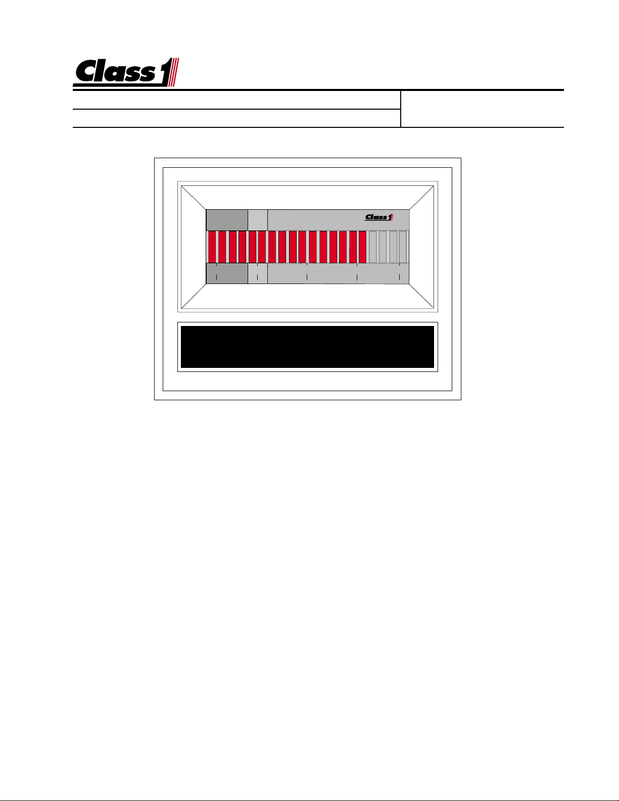
0 25 50 75 100
BREATHING AIR
The
Class1
Breathing Air Display is designed to provide firefighters with a
visible indication of breathing air remaining and an audible warning when
there is less than 20% air remaining. The alarm will not activate when there is
less than 50 PSI of air in the system, this silences the alarm when the air
supply is turned off.
The display represents air volume information in an easy to interpret LED
bargraph display as a percentage of maximum calibrated pressure. The
Breathing Air Display includes a visual warning and an auxiliary warning alarm
output.
When the relative volume of air remaining reaches 25%, the bars will begin to
flash and the alarm output becomes active when system pressure drops to
20%. The alarm can be silenced with an alarm silence switch. Once the
alarm is silenced, it will remain silent for five (5) minutes or until the unit is
turned off and then back on, and is reset whenever the volume of air exceeds
20%.
page 1 of 8 pages
Page 2
Engineering
Standards
Name
Identifier Instructions
Digital Breathing Air Remaining System
Class1 Class1
The
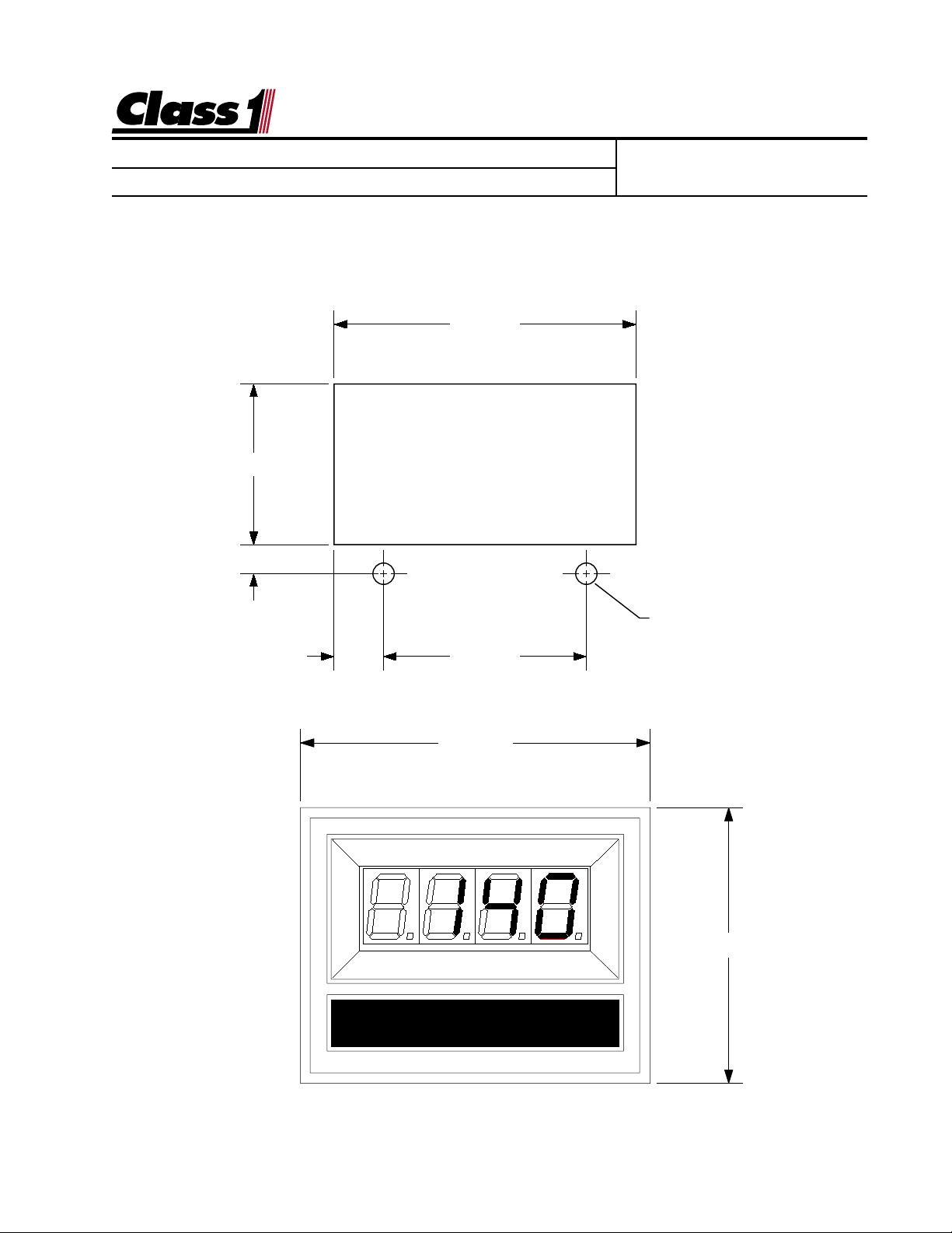
Class1 digital displa y mounts in a 2.85” b y 1.55” cutout.
Class1 Class1
Overall area necessary for installation is 2.5” by 3.2”.
Two 0.20 diameter holes are provided f or mounting screws.
1.510
.277
Engineering Standard Number
C1-102263-A
2.840"
.470 1.900
3.125"
DIGITAL DISPLAY
Ø 0.201"
(2) HOLES
2.462"
page 2 of 8 pages
Page 3
Engineering
Standards
Name
Identifier Instructions
Digital Breathing Air Remaining System
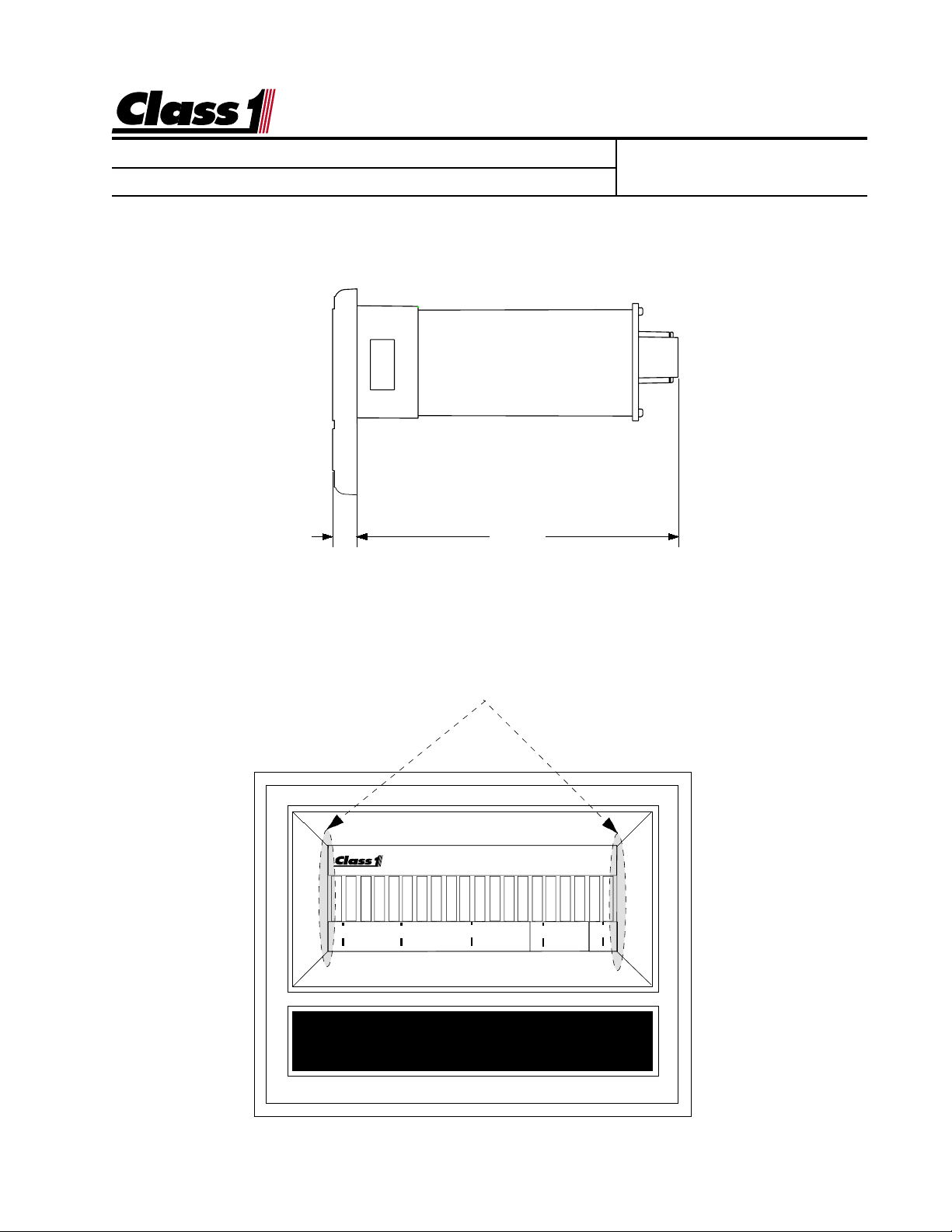
0.285" 3.832"
Engineering Standard Number
C1-102263-A
Location of magnetic switches
0 25 50 75 100
BAR GRAPH DISPLAY
page 3 of 8 pages
Page 4

Engineering
Standards
Name
Identifier Instructions
Digital Breathing Air Remaining System
Engineering Standard Number
C1-102263-A
Display Calibration for Gauges with bargraph displays
The calibration mode is entered by the use of a “password”.
There are two magnetic switches, one located at each side of the display.
These switches are activated with the use of a magnet.
Switch activation is visually confirmed by the toggling of the four closest bars on the display to
the switch. If they are on they will turn off, if they are off they will turn on.
If the password is correctly entered, the leftmost bar will turn on and flash. This indicates that the
display is ready to be calibrated for the low set point.
With the system adjusted to the minimum calibration point (the system should be empty or at the
lowest pressure condition) activate the left switch and then the right switch.
The rightmost bar will begin to flash, indicating the display is ready for the high set point calibration.
Adjust the system to it’s maximum operating condition. Activate the right switch followed by the left
switch.
The display will return to normal operation and indicate current system status as a percentage of
maximum capacity.
Calibration for Breathing Air Gauge installations:
Empty Cylinder (Closed Valve)
With the air bottle closed and the system purged, enterthe calibration password.
LEFT LEFT LEFT RIGHT RIGHT RIGHT
The left (0%) bar will flash to indicate that you are ready to calibrate for an empty system.
Activate the left switch followed by the right switch.
The right (100%) bar will flash to indicate that the display is ready to calibrate for a full system.
Maximum Air (Full Cylinder/Open Valve)
With a full air bottle and the valve open actuate the right switch and then the left switch.
Calibration is complete.
Calibration should be accomplished using an air cylinder filled to the locally
established maximum pressure.
page 4 of 8 pages
Page 5

Engineering
Standards
Name
Identifier Instructions
Digital Breathing Air Remaining System
Engineering Standard Number
C1-102263-A
All of the digital displays have a built in lamp test feature.
The password to activate this function is L L R L L.
When activated, all segments on the display LED’s will illuminate for a few
seconds and then return to normal operation.
The digital displays that utilize a pressure sensor have a sensor check feature.
The password to activate this function is L R R L R R.
page 5 of 8 pages
Page 6

Engineering
Standards
Name
Identifier Instructions
Digital Breathing Air Remaining System
Wiring Diagram for the Digital Breathing Air Remaining Gauge.
DTM06-08SA
0462-201-20141 20 Ga.
1 Alarm OUT (ground)
2 PSI IN (Pressure)
3 Sensor + 10 VDC
4 Power + 12 VDC
5 Ground
6NC
7NC
8 Alarm Silence (ground)
Wire Insertion View
8
7
6
5
1
PSI Signal
2
PSI Supply
3
4
BLACK
Alarm OUT
BLACK
RED
RED
Red
Black
Engineering Standard Number
C1-102263-A
0.410"
1.125"
1.425"
OEM Power Feed
12 VDC
Ground
Black
Red
CONNECTOR
PIN COLOR
1 RED
2 BLACK
PROVIDED HARNESS
Pressure Transducer
PIN COLOR
1 PLUG
2 BLACK
3 RED
4 RED
5 BLACK
6 PLUG
7 PLUG
8 PLUG
MANUALS\DIGITAL\AIR_LEFT\O2-wire.AI
page 6 of 8 pages
Page 7

Name
Identifier Instructions
PRIMARY DISPLAY
PIN COLOR CIRCUIT
1 OEM Alarm
2 BLACK Signal
3 RED 10 VDC
4 RED V IGN
5 BLACK GND
6 Black Sensor 7 PLUG --8 OEM Silence
SENSOR
PIN COLOR CIRCUIT
1 RED 10 VDC
2 BLACK SIGNAL
Ignition
2.5'
DISPLAY 2 Signal Wire
10'
Turntable
or
Reel
2.5'
DUAL OUTPUT CONVERTER
PIN COLOR CIRCUIT
1 BLACK SIGNAL 1
2 WHITE SIGNAL 2
3 BLACK XDucer IN
4 RED V IGN
5 BLACK GND
6 PLUG --
Ground
5'
2.5'
7 RED T V+
8 PLUG --
12"
12"
Digital Breathing Air Remaining System
Engineering
Standards
Secondary DISPLAY
PIN COLOR CIRCUIT
1 OEM Alarm
2 White Signal
3 PLUG --4 RED V IGN
5 BLACK GND
page 7 of 8 pages
6 PLUG --7 PLUG --8 OEM Silence
Wiring a dual display, single transmitter installation uses a PN103282 Dual Current Amplifier and
a dual harness PN 103283.
Connections are as shown. For a secondary display where a minimal wire configuration is needed, contact Class1
Product Support (1-800-533-3569).
Engineering Standard Number
C1-102263-A
Page 8

Engineering
Standards
Name
Identifier Instructions
Digital Breathing Air Remaining System
(ground) Switch 8
Sensor Ground 6
System Ground 5
0462-201-20141 20 Ga.
Pulses IN 7
DTM06-08SA
1 Alarm OUT (grund)
8
7
6
5
Wire Insertion View
1
2
2 PSI IN
3
3 Sensor +5/10 VDC
4
4 System Power
Engineering Standard Number
C1-102263-A
The display does not illuminate.
The display must have power at terminal 4 and ground at terminal 5. With the
connector removed, check betw een pins 4 and 5 f or 12 VDC , if 12 v olts is present with
the correct polarity, replace the display. If v oltage and/or g round is not present, check
the vehicle wiring and display harness terminations.
The air gauge has a single bar traveling back and f orth across the display .
There is a problem with the pressure transducer (PN 102162) or wiring. At the
transducer connector , check f or 10 VDC between the red wire and ground. This is sent
from the display and must be correct f or the transducer to function. Connect the red wire
to the transducer and check for current at the black wire. This is a current (4-20mA)
7500 PSI transducer . With an empty tank, this voltage should be 4 mA and at 3000 PSI
approximately 10.5 mA., if it is not, replace the transducer. Check for current at the
display pin 2 signal). If there is no current, check the wiring from the transducer to the
display. If the current is present at pin 2, replace the displa y.
page 8 of 8 pages
 Loading...