

Page 1
Engineering
Standards
Name Digital Aerial Warning Display
Identifier Installation Information
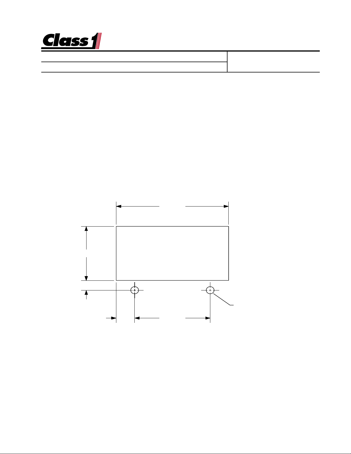
Installation
The display mounts in a 2.84” by 1.51” cutout.
Overall area necessary for installation is 3.2” by 2.5”.
Two 0.201d holes are provided for mounting scre ws.
2.840"
Engineering Standard Number
C1-102342-A
1.510
.277
Ø 0.201"
(2) HOLES
.470 1.900
page 1 of 6 pages
Page 2
Engineering
Standards
Name Digital Aerial Warning Display
Identifier Installation Information
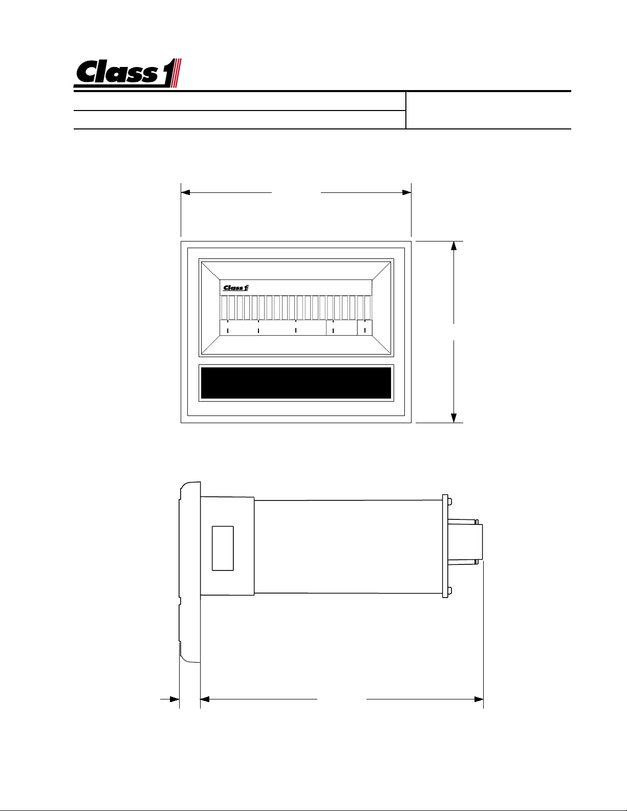
3.125"
0 25 50 75 100
DIGITAL DISPLAY
Engineering Standard Number
C1-102342-A
2.462"
0.285" 3.832"
page 2 of 6 pages
Page 3

Engineering
Standards
Name Digital Aerial Warning Display
Identifier Installation Information
Electrical
The Aerial Warning Display is connected to the OEM harness with a Deutsch 8 pin
mini-connector.
Mating Connector: DTM06-08S
Locking Wedge WM-8S
Mating Terminal: 0462-201-20141 20 gauge socket
12 VDC
P.N.1800060
Display Power
Alarm Output (Ground)
Engineering Standard Number
C1-102342-A
PIN COLOR FUNCTION
1 OEM Alarm OUT (ground)
2 WHITE PRIMARY SIGNAL
3 RED SENSOR SUPPLY
4 RED POWER IN
5 BLACK GROUND IN
6 BLACK NC
7 WHITE SEC. SIGNAL (opt.)
8 OEM Alarm Test (ground)
Primary (barrel) Transducer Cable
Secondary (rod) Transducer Cable (OPTIONAL)
WIRE COLOR FUNCTION
1 RED SENSOR SUPPLY
2 WHITE SENSOR SIGNAL
Display Ground
Alarm T est
0462-201-20141 20 Ga.
Switch 8
Pulses IN 7
Sensor Ground 6
System Ground 5
DTM06-08SA
1N/C
1
8
2
7
6
5
Wire Insertion View
2 PSI IN
3
3 Sensor +5/10 VDC
4
4 System Power
Mating connector viewed from the wire end
page 3 of 6 pages
Page 4

Engineering
Standards
Name Digital Aerial Warning Display
Identifier Installation Information
PIN COLOR CIRCUIT
1 BLACK SIGNAL 1
2 WHITE SIGNAL 2
3 BLACK XDucer IN
4 RED V IGN
5 BLACK GND
6 PLUG --
7 RED T V+
DUAL OUTPUT CONVERTER
8 PLUG --
Engineering Standard Number
C1-102342-A
12"
12"
PRIMARY DISPLAY
PIN COLOR CIRCUIT
1 OEM Alarm
2 BLACK Signal
3 RED 10 VDC
4 RED V IGN
5 BLACK GND
6 Black Sensor -
7 PLUG ---
Ground
Ignition
8 OEM Silence
2.5'
5'
2.5'
or
10'
2.5'
SENSOR
PIN COLOR CIRCUIT
1 RED 10 VDC
2 BLACK SIGNAL
Reel
Turntable
DISPLAY 2 Signal Wire
Secondary DISPLAY
PIN COLOR CIRCUIT
1 OEM Alarm
2 White Signal
3 PLUG ---
4 RED V IGN
5 BLACK GND
6 PLUG ---
7 PLUG ---
8 OEM Silence
Dual Display Wiring
page 4 of 6 pages
Page 5

Engineering
Standards
Name Digital Aerial Warning Display
Identifier Installation Information
Calibration for dual and single transducer installations:
Calibration for Gauges with bargraph displays
The calibration mode is entered by the use of a “password”.
There are two magnetic switches , one located at each side of the display .
These switches are activated with the use of a magnet.
Switch activation is visually confirmed by the toggling of the closest bar on the display to the switch. If it is on it will turn off, if it is off it will turn on.
Location of magnetic switches
0 25 50 75 100
BAR GRAPH DISPLAY
Engineering Standard Number
C1-102342-A
MINIMUM LOAD With the ladder retracted, just raised out of the cradle and no load
placed on the device, enter the calibr ation password.
L L L R R R
The left (0%) bar will flash to indicate that you are ready to calibrate f or the minimum
load.
Activate the left switch f ollo wed by the right s witch.
The right (100%) bar will flash to indicate that the display is ready to calculate for
maximum load.
MAXIMUM LOAD With the ladder extended and maximum load placed at the end of
the aerial device actuate the right switch and then the left s witch.
Calibration is complete
NOTE: AERIAL MANUFACTURERS MUST ENSURE THAT THE LIFT CYLINDER(S) DO NOT BOTTOM
DURING OPERATIONS. THIS WOULD CAUSE AN ERRONEOUS HYDRAULIC PRESSURE READING AND
OUT
WARNING SYSTEM WILL NOT OPERATE AS DESIGNED.
THE
page 5 of 6 pages
Page 6

Engineering
Standards
Name Digital Aerial Warning Display
Identifier Installation Information
Engineering Standard Number
C1-102342-A
Operation
0 25 50 75 100
LOW LEVEL LOADING
The
dangerous loading conditions when an aerial device is operated at low angles
of elevation. Live loads (factors that increase this load such as ice, occupants on the ladder, water load, extra equipment, etc.) are instantly taken into
account by the system and displayed to the operator.
Class1
Aerial Loading Display is designed to warn aerial operators of
The display presents load information in an easy to interpret LED bar graph
display as a percentage of maximum calibrated load and includes a visual
and aural warnings.
When the aerial load approaches the maximum load (approx. 80%), 18 bars
will be illuminated on the display. When the load is increased to 90%-100%,
19-20 bars will be displayed and the display will begin to flash, when the
maximum load is exceeded by 50-100 pounds, an alarm output is activated
that can be used to drive a variety of warning systems that can notify the
operator of a potentially hazardous condition.
The alarm resets when the device comes out of an overload condition.
NOTE: THE DISPLAY PROVIDES A WARNING ONL Y AND CANNOT PREVENT A TIPOVER. THE
AERIAL
STRUCTIONS AND OPERATORS MUST BE THOROUGHLY TRAINED.
DEVICE MUST BE OPERATED IN STRICT ACCORDANCE WITH THE MANUFACTURER’S IN-
A test switch can be installed to test the alarm output. This function is only
available when the unit is displaying less than 11 bars.
page 6 of 6 pages
c:\manuals\digital\LoadLevel\aerialESN.p65
 Loading...