

Page 1
FORM-ENG-0018 REV A 06-02-03
ISO 9001 CERTIFIED
607 NW 27th Ave
Phone: (352) 629-5020 or 800-533-3569
Ocala, FL 34475
Fax: (352)-629-2902
TECHNICAL PRODUCT DATASHEET
Electronic Throttle
(Analog version)
P/N 119971
Page 2

FORM-ENG-0018 REV A 05-27-03
607 NW 27th Ave
Ocala, FL 34475
Ph: 352-629-5020 or 1-800-533-3569
Fax : 352-629-2902 or 1-800-520-3473
PRODUCT GROUP
PRODUCT
TECHNICAL DATA SHEET
THROTTLE CONTROL
Twister Electronic Throttle (Analog version)
P/N 119971 REV 1.20
PAGE
DATE 10/1/2010
BY AMS
1 OF 16
1.
REVISION LOG ..................................................................................................................................................................................... 2
2. PART NUMBERS .................................................................................................................................................................................. 3
2.1. SYSTEM PART NUMBERS .................................................................................................................................................................. 3
3. OVERVIEW ............................................................................................................................................................................................ 4
3.1. PRODUCT DESCRIPTION ................................................................................................................................................................... 4
3.2. THROTTLE READY LED INDICATOR .................................................................................................................................................... 5
3.3. ACTIVE LED INDICATOR ................................................................................................................................................................... 5
3.4. CONTROL KNOB ............................................................................................................................................................................... 5
3.5. IDLE BUTTON.................................................................................................................................................................................... 5
4. CONFIGURATION ................................................................................................................................................................................. 6
4.1. ENTERING PASSWORDS .................................................................................................................................................................... 6
4.2. INTERLOCK POLARITY ....................................................................................................................................................................... 6
4.2.1. Positive polarity (default) .......................................................................................................................................................... 7
4.2.2. Ground polarity ......................................................................................................................................................................... 7
4.3. KNOB ROTATION .............................................................................................................................................................................. 7
4.3.1. Clockwise rotation increases RPM (default) ............................................................................................................................. 7
4.3.2. Counter-clockwise rotation increases RPM .............................................................................................................................. 7
4.4. INITIAL DEADBAND CLICKS ................................................................................................................................................................ 8
4.5.
LOAD DEFAULTS ............................................................................................................................................................................... 8
4.6. ENGINE RPM RANGE CONFIGURATION .............................................................................................................................................. 8
4.6.1. Idle RPM configuration ............................................................................................................................................................. 9
4.6.2. Maximum RPM configuration ................................................................................................................................................... 9
4.7.
OUTPUT RAMP RATE ......................................................................................................................................................................... 9
5. OPERATION ........................................................................................................................................................................................ 10
5.1. INITIALIZATION ............................................................................................................................................................................... 10
5.2. INTERLOCKING (ENABLING THE TWISTER) ........................................................................................................................................ 10
5.3. CONTROLLING ENGINE SPEED ......................................................................................................................................................... 11
5.3.1. Returning the engine speed to idle ......................................................................................................................................... 12
6. MOUNTING & INSTALLATION........................................................................................................................................................... 13
6.1. PANEL CUTOUT DIMENSIONS ........................................................................................................................................................... 13
6.2. TWISTER SIDE-VIEW DIMENSIONS .................................................................................................................................................... 13
6.3. MAINTENANCE ............................................................................................................................................................................... 14
7. WIRING ................................................................................................................................................................................................ 14
7.1. TWISTER CONNECTOR .................................................................................................................................................................... 14
7.2. TWISTER WIRING ............................................................................................................................................................................ 14
8. TECHNICAL DETAILS ........................................................................................................................................................................ 15
9. REFERENCES ..................................................................................................................................................................................... 16
9.1. LIST OF FIGURES ............................................................................................................................................................................ 16
9.2. LIST OF TABLES .............................................................................................................................................................................. 16
9.3. LIST OF PASSWORDS ...................................................................................................................................................................... 16
Manual P/N 120478
Page 3

FORM-ENG-0018 REV A 05-27-03
607 NW 27th Ave
Ocala, FL 34475
Ph: 352-629-5020 or 1-800-533-3569
Fax : 352-629-2902 or 1-800-520-3473
1. Revision Log
Rev Date Changes
1.00 11/16/2009 Initial revision
1.10 9/7/2010 Clarified password entry.
1.20 10/1/2010 Added passwords for “slow” output mode
PAGE
PRODUCT GROUP
PRODUCT
TECHNICAL DATA SHEET
THROTTLE CONTROL
Twister Electronic Throttle (Analog version)
P/N 119971 REV 1.20
DATE 10/1/2010
BY AMS
Product specifications in this manual are subject to change without notice.
2 OF 16
Manual P/N 120478
Page 4

FORM-ENG-0018 REV A 05-27-03
607 NW 27th Ave
Ocala, FL 34475
Ph: 352-629-5020 or 1-800-533-3569
Fax : 352-629-2902 or 1-800-520-3473
PRODUCT GROUP
PRODUCT
2. Part numbers
2.1. System part numbers
Twister Electronic Throttle (analog) system kit TWIST-A
TECHNICAL DATA SHEET
THROTTLE CONTROL
Twister Electronic Throttle (Analog version)
P/N 119971 REV 1.20
PAGE
DATE 10/1/2010
BY AMS
3 OF 16
Kit includes
Twister Electronic Throttle (analog) QTY-1 119971
Twister main system harness QTY-1 120430
Knob rotation direction label set QTY-1 120462
Documentation (available from Class 1’s website - www.class1.com)
Twister Electronic Throttle Manual (this manual) 120478
Twister Quick Manual 120319
Manual P/N 120478
Page 5
FORM-ENG-0018 REV A 05-27-03
607 NW 27th Ave
Ocala, FL 34475
Ph: 352-629-5020 or 1-800-533-3569
Fax : 352-629-2902 or 1-800-520-3473
PRODUCT GROUP
PRODUCT
3. Overview
3.1. Product description
The Twister Electronic Throttle (p/n 119971) controls engine speed using a variable analog voltage connected to the
engine ECM for remote throttle applications. The Twister’s analog voltage range is 0.235 volts to 4.448 volts and the
minimum (idle) and maximum voltages can be configured between the standard range for specific engine
manufacturer requirements (refer to section 4.6).
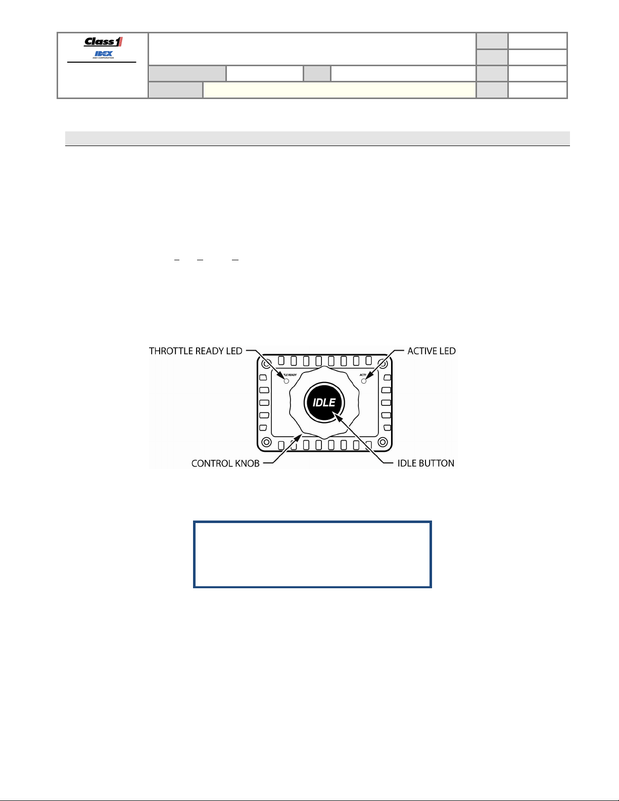
The Twister utilizes L
READY LED is on the left-side of the control knob and the blue ACTIVE LED is on the right-side of the control knob.
The Twister has a control knob and an idle button for the operator to control engine speed. The control knob allows
manipulation of the engine speed within the configured (and engine allowable) RPM range. The idle button returns
the engine speed to the configured idle RPM.
TECHNICAL DATA SHEET
THROTTLE CONTROL
Twister Electronic Throttle (Analog version)
P/N 119971 REV 1.20
PAGE
DATE 10/1/2010
BY AMS
4 OF 16
ight Emitting Diodes (LED) to convey status information to the operator. The green THROTTLE
Figure 1. Twister controls and indicators.
THROTTLE READY LED………………… section 3.2
ACTIVE LED………………………………. section 3.3
Control knob……………………………….. section 3.4
Idle button………………………………….. section 3.5
Manual P/N 120478
Page 6

FORM-ENG-0018 REV A 05-27-03
607 NW 27th Ave
Ocala, FL 34475
Ph: 352-629-5020 or 1-800-533-3569
Fax : 352-629-2902 or 1-800-520-3473
3.2. Throttle ready LED indicator
The green THROTTLE READY LED indicator shows the status of the Twister interlock input (pin 3) and analog signal
diagnostic information.
FAST FLASH
DOUBLE BLINK NOT PERMITTED
3.3. Active LED indicator
The blue ACTIVE LED indicator shows the status of the Twister control.
PRODUCT GROUP
PRODUCT
Twister Electronic Throttle (Analog version)
LED state Throttle control Description
ON PERMITTED Twister interlock input (pin 3) is active.
OFF NOT PERMITTED Twister interlock input (pin 3) is NOT active.
(10 Hz)
NOT PERMITTED
LED state Throttle control Description
ON ACTIVE The twister is in control of engine RPM.
OFF NOT ACTIVE The Twister is not controlling the engine RPM (engine at idle).
FLASHING AT RPM LIMIT
TECHNICAL DATA SHEET
THROTTLE CONTROL
Table 1. Throttle ready LED states.
P/N 119971 REV 1.20
Analog signal error (voltage too low).
Verify analog +5 VDC reference and signal line voltage.
Analog signal error (voltage too high).
Verify analog ground reference and signal line voltage.
The Twister’s control knob is being rotated while the analog output
signal voltage is already at the configured limit (minimum or
maximum).
PAGE
DATE 10/1/2010
BY AMS
5 OF 16
Table 2. Active LED states.
3.4. Control knob
The control knob is the operator’s interface for RPM control. The control knob is rotated to change the engine speed
(RPM). The control knob can be configured to increase engine speed with clockwise or counter-clockwise rotation
(section 4.3).
3.5. Idle button
The idle button is the operator’s interface to return the engine’s speed to its idle RPM. Press and hold the idle button
for a half-second to ramp the engine speed to idle and release active engine control from the Twister. The Twister
ramps the output signal down at a rate of 0.9 volts per second.
Manual P/N 120478
Page 7

FORM-ENG-0018 REV A 05-27-03
607 NW 27th Ave
Ocala, FL 34475
Ph: 352-629-5020 or 1-800-533-3569
Fax : 352-629-2902 or 1-800-520-3473
PRODUCT GROUP
PRODUCT
4. Configuration
4.1. Entering passwords
The Twister utilizes passwords to modify its operational parameters. All operational parameters are stored in memory
and will not be lost when power is disconnected.
TECHNICAL DATA SHEET
THROTTLE CONTROL
Twister Electronic Throttle (Analog version)
P/N 119971 REV 1.20
PAGE
DATE 10/1/2010
BY AMS
6 OF 16
Figure 2. Password entry mode.
To enter a password:
Press and hold the IDLE button until the ACTIVE LED blinks twice (two seconds). Continue holding the
IDLE button while entering the password.
A clockwise
rotation will turn the ACTIVE LED ON for a half- second and a counter-clockwise rotation
will turn the THROTTLE READY LED ON for a half-second. Wait for the LED indication to turn OFF before
rotating the knob again.
A rotation consists of at least one tactile click and a single rotation event is complete when the knob remains
stationary for at least half a second.
If an error is made while entering a password, release the IDLE button to clear and then re-attempt the
password from the beginning.
Invalid password entry
The THROTTLE READY and ACTIVE LEDs will quickly flash numerous times to indicate an attempted password is
invalid.
Manual P/N 120478
Page 8

FORM-ENG-0018 REV A 05-27-03
607 NW 27th Ave
Ocala, FL 34475
Ph: 352-629-5020 or 1-800-533-3569
Fax : 352-629-2902 or 1-800-520-3473
4.2. Interlock polarity
The Twister interlock input (pin 3) must be active before control of the engine speed is possible. The Twister interlock
input can be configured for positive (default) or ground input polarity.
PRODUCT GROUP
PRODUCT
TECHNICAL DATA SHEET
THROTTLE CONTROL
Twister Electronic Throttle (Analog version)
P/N 119971 REV 1.20
PAGE
DATE 10/1/2010
BY AMS
7 OF 16
4.2.1. Positive polarity (default)
Positive polarity interlock configuration password:
4.2.2. Ground polarity
Ground polarity interlock configuration password:
4.3. Control knob rotation
The control knob can be configured to increase engine RPM with clockwise or counter-clockwise rotation. Included
with the Twister is a label set (p/n 120462) which contains a clockwise increase and a counter-clockwise increase
label. Affix the label to the Twister which indicates the configured knob rotation direction.
Figure 3. Rotation direction labels (p/n 120462).
4.3.1. Clockwise rotation increases RPM (default)
Clockwise knob rotation configuration password:
4.3.2. Counter-clockwise rotation increases RPM
Clockwise knob rotation configuration password:
Manual P/N 120478
Page 9

FORM-ENG-0018 REV A 05-27-03
607 NW 27th Ave
Ocala, FL 34475
Ph: 352-629-5020 or 1-800-533-3569
Fax : 352-629-2902 or 1-800-520-3473
4.4. Initial deadband clicks
The Twister requires a number tactile clicks of the control knob in the increase direction before it will allow engine
control. The default number of tactile clicks is five (5) but can be changed to one (1) or ten (10).
Initial deadband clicks required = 1:
Initial deadband clicks required = 5 (default):
Initial deadband clicks required = 10:
4.5. Load defaults
PRODUCT GROUP
PRODUCT
TECHNICAL DATA SHEET
THROTTLE CONTROL
Twister Electronic Throttle (Analog version)
P/N 119971 REV 1.20
PAGE
DATE 10/1/2010
BY AMS
8 OF 16
The Twister’s default configurations are:
Knob increase direction: Clockwise
Interlock polarity: Positive voltage
Maximum output signal voltage: 3.990 VDC
Idle output signal voltage: 0.235 VDC
Control knob initial dead band: 5 initial tactile clicks
4.6. Engine RPM range configuration
The Twister allows configuration of its idle output signal voltage and maximum output signal voltage which directly
affects the engine’s RPM range. The defaults are 0.235 volts at idle and 3.990 volts at maximum.
The idle offset voltage level affects the Twister’s maximum voltage level. When the idle offset voltage is configured to
its lowest level (0.235 volts) the maximum attainable voltage is 3.990 volts. When the idle offset voltage is configured
to its maximum level (2.392 volts) the maximum attainable voltage is 4.448 volts. The graph below (Figure 4) shows
the relationship between the configured idle offset voltage and its associated maximum voltage level.
Manual P/N 120478
Figure 4. Idle offset voltage versus maximum voltage.
Page 10

FORM-ENG-0018 REV A 05-27-03
607 NW 27th Ave
Ocala, FL 34475
Ph: 352-629-5020 or 1-800-533-3569
Fax : 352-629-2902 or 1-800-520-3473
4.6.1. Idle RPM configuration
Enter the password:
PRODUCT GROUP
PRODUCT
TECHNICAL DATA SHEET
THROTTLE CONTROL
Twister Electronic Throttle (Analog version)
P/N 119971 REV 1.20
PAGE
DATE 10/1/2010
BY AMS
9 OF 16
Release the IDLE button.
The Twister sets its output signal voltage to the lowest point. Use the control knob to increase the output signal
voltage until the engine begins to increase its RPM. Use the control knob to find the base limit of control and then
press the IDLE button to save the output signal voltage as the idle voltage.
Engine manufacturers will program their ECMs for a curb idle. The Twister cannot force the engine ECM to attain a
lower RPM than the manufacturers curb idle.
4.6.2. Maximum RPM configuration
Enter the password:
Release the IDLE button.
The Twister sets its output signal voltage the configured idle voltage. Use the control knob to increase the output
signal voltage until the desired maximum RPM is attained. Press the IDLE button to save the output signal voltage
as the maximum voltage.
Engine manufacturers will program their ECMs for a maximum safe RPM limit. The Twister cannot force the engine
ECM to attain more RPM than the manufacturers limit.
4.7. Output Ramp Rate
The Twister (software version 1.2 and above) can be set for two different output ramp rates. The normal mode, which
is the default, increases/decreases the output signal voltage for every click of the control knob. The slow mode
increases/decreases the output signal voltage for every two clicks of the control knob, effectively creating a slower
response to the user input. In slow mode, the ramp time when returning to IDLE using the IDLE button is also twice as
long. The slow mode can be useful in matching the Twister to certain engines if the default ramp speeds are too fast.
Normal Mode (default):
Slow Mode:
Manual P/N 120478
Page 11

FORM-ENG-0018 REV A 05-27-03
607 NW 27th Ave
Ocala, FL 34475
Ph: 352-629-5020 or 1-800-533-3569
Fax : 352-629-2902 or 1-800-520-3473
5. Operation
5.1. Initialization
The Twister uses a two (2) second initialization cycle. The green throttle ready LED and blue active LED will be ON
during the initialization. The Twister will then begin normal operation.
PRODUCT GROUP
PRODUCT
TECHNICAL DATA SHEET
THROTTLE CONTROL
Twister Electronic Throttle (Analog version)
P/N 119971 REV 1.20
PAGE
DATE 10/1/2010
BY AMS
10 OF 16
Figure 5. Twister initialization.
5.2. Interlocking (enabling the Twister)
The Twister will not allow control of the engine speed until the interlock input (pin 3) has been activated. The interlock
input is activated when the proper voltage level is applied. The interlock voltage can be configured for system voltage
(default) or system ground (see section 0).
Figure 4 illustrates a typical interlocking scheme with the Twister’s interlock configured for system voltage. In this
example the OEM makes certain that the park brake and transmission are in the proper modes before allowing
system voltage to pass through to the Twister’s interlock input (pin 3).
Figure 6. Twister interlocking example.
The Twister’s green throttle ready LED will be ON when the proper voltage is applied to the interlock input. This
indicates that the Twister is ready for operator initiated control via the control knob. Refer to table Table 1 in section
3.2 for a description of the throttle ready LED status indication.
Manual P/N 120478
The OEM is responsible for creating a safe interlocking scheme to enable the Twister.
Page 12

FORM-ENG-0018 REV A 05-27-03
607 NW 27th Ave
Ocala, FL 34475
Ph: 352-629-5020 or 1-800-533-3569
Fax : 352-629-2902 or 1-800-520-3473
5.3. Controlling engine speed
The Twister allows the operator to control of the engine’s speed by rotating the control knob as long as the interlock is
active.
The blue ACTIVE LED will be ON once the control knob has been rotated in the increase RPM direction enough
clicks to overcome the configured initial deadband (default is 5 clicks).
Each tactile click of the control knob equals a 0.014 volt increase of the analog output signal voltage. With most
manufacturers this equals from 5 to 10 RPM per tactile click.
PRODUCT GROUP
PRODUCT
TECHNICAL DATA SHEET
THROTTLE CONTROL
Twister Electronic Throttle (Analog version)
P/N 119971 REV 1.20
PAGE
DATE 10/1/2010
BY AMS
11 OF 16
Figure 7. Active LED.
The blue ACTIVE LED indicator shows the status of the twister control (see Table 2 in section 3.3). The ACTIVE
LED will blink when the control knob is being rotated while the output signal voltage is already at the configured limit
(minimum or maximum voltage).
5.3.1. Control knob initial deadband
The Twister requires a number tactile clicks of the control knob in the increase direction before it will allow engine
control. This initial deadband keeps the Twister from inadvertently controlling engine speed caused by accidental
bumps, vibration, etc. The default number of tactile clicks is five (5) with each click occurring within a half-second
of the last. The blue ACTIVE LED activates and throttle control is allowed once the number of tactile clicks has
been established.
Manual P/N 120478
Figure 8. Initial deadband explanation.
Page 13

FORM-ENG-0018 REV A 05-27-03
607 NW 27th Ave
Ocala, FL 34475
Ph: 352-629-5020 or 1-800-533-3569
Fax : 352-629-2902 or 1-800-520-3473
PRODUCT GROUP
PRODUCT
In the previous graphic (Figure 8) the first three tactile clicks are more than a half-second apart and are not counted
for the required number of deadband clicks. The next series of tactile clicks are a half-second (or less) apart and
the deadband counter counts each one up to the required number of clicks (5). The Twister then activates the blue
ACTIVE LED and allows active throttle control. Subsequent tactile clicks change the RPM of the engine and the
timing between clicks is not important. The initial deadband requirement will not be required again until the IDLE
button has been pressed and the engine RPM has been reduced to curb idle.
5.3.2. Returning the engine speed to idle
Press the idle button for a half-second to return the engine speed to idle. The twister will ramp the engine speed
from the current RPM down to the configured idle RPM at which time the blue ACTIVE LED will turn OFF to
indicate that idle has been reached.
TECHNICAL DATA SHEET
Twister Electronic Throttle (Analog version)
THROTTLE CONTROL
PAGE
DATE 10/1/2010
P/N 119971 REV 1.20
BY AMS
12 OF 16
Figure 9. Pressing the idle button.
Manual P/N 120478
Page 14

FORM-ENG-0018 REV A 05-27-03
607 NW 27th Ave
Ocala, FL 34475
Ph: 352-629-5020 or 1-800-533-3569
Fax : 352-629-2902 or 1-800-520-3473
PRODUCT GROUP
PRODUCT
6. Mounting & installation
6.1. Panel cutout dimensions
Mount the Twister on the operator’s panel with four #6 screws and nuts.
TECHNICAL DATA SHEET
THROTTLE CONTROL
Twister Electronic Throttle (Analog version)
P/N 119971 REV 1.20
PAGE
DATE 10/1/2010
BY AMS
13 OF 16
Figure 10. Installation dimensions in inches [millimeters].
6.2. Twister side-view dimensions
Figure 11. Side view dimensions in inches [millimeters].
Manual P/N 120478
Page 15

FORM-ENG-0018 REV A 05-27-03
607 NW 27th Ave
Ocala, FL 34475
Ph: 352-629-5020 or 1-800-533-3569
Fax : 352-629-2902 or 1-800-520-3473
PRODUCT GROUP
PRODUCT
6.3. Maintenance
The Twister does not require regular maintenance. The control knob does not require lubrication.
7. Wiring
7.1. Twister connector
The module has one connector and the following definitions apply:
Mating connector: Deutsch DT06-6S GRAY
Mating sockets: Deutsch 0462-201-16141
Gold mating sockets: Deutsch 0462-201-1631
Recommended wire gage: 16-20 AWG
Wedge lock: W6S
PIN CIRCUIT DESCRIPTION
1 SYS POWER (INPUT) – battery voltage (+9VDC…+32VDC)
2 SYS GROUND (INPUT) – battery ground
3 INTERLOCK (INPUT) – Positive/Ground polarity (configurable)
4 SIGNAL REF + (INPUT) – ECM reference voltage, +5 VDC
5 SIGNAL REF - (INPUT) – ECM reference voltage, ground
6 OUTPUT SIG (OUTPUT) – ECM remote throttle control voltage
TECHNICAL DATA SHEET
THROTTLE CONTROL
Twister Electronic Throttle (Analog version)
P/N 119971 REV 1.20
PAGE
DATE 10/1/2010
BY AMS
14 OF 16
7.2. Twister wiring
Figure 12. Twister harness connections.
Manual P/N 120478
Page 16

FORM-ENG-0018 REV A 05-27-03
607 NW 27th Ave
Ocala, FL 34475
Ph: 352-629-5020 or 1-800-533-3569
Fax : 352-629-2902 or 1-800-520-3473
PRODUCT GROUP
PRODUCT
8. Technical Details
Product category Throttle control (analog)
Voltage range +9VDC…+32VDC
Maximum current draw
@13.8VDC
@27.6VDC
Temperature range -40ºF…+185ºF (-40ºC…+85ºC)
Environmental range IP 67
LED 2 LEDs (green and blue) to indicate status
Electrical protection
Electrical performance
Environmental performance
Mechanical performance
Dimensions (W x H x D)
in inches [millimeters]
Weight in ounces [grams] 22.8 [646.4]
TECHNICAL DATA SHEET
THROTTLE CONTROL
Twister Electronic Throttle (Analog version)
Logic supply+ input (pin 1 of 6-pin connector)
240 mA
163 mA
Internal thermal fuse (750mA on pin 1 of black 6-pin connector)
Transient voltage protected to SAE J1113 specification for heavy duty trucks (24V)
Load dump voltage protected to SAE J1113 specification for heavy duty trucks (24V)
Immunity to Radiated Electromagnetic Fields– Bulk Current
Injection (BCI) method, Class C device
Reverse voltage protection on power leads (pins 1 and 2 of 6-pin
connector), Class C device
Overvoltage due to failing generator, Class A device ISO 16750-2
Immunity to conducted transients on power leads, Class C device
(24V)
Immunity to Electrostatic Discharge – powered and unpowered
modes
Immunity to radiated electromagnetic fields, Class C device SAE J1113-21
Conducted emission on power leads (level 3 limits) SAE J1113-41
Radiated emissions, absorber-lined shielded enclosure (level 2
limits)
Reset behavior on voltage drop 24V, Class C device ISO 16750-2
Thermal shock
Exposure to humidity
Thermal shock due to splash
Pressure cleaning
Exposure to salt spray atmosphere/fog
Exposure to outdoor UV
Resonance dwell
Random vibration
Mechanical shock
4.438 [112.73] x 3.188 [80.98] x 2.312 [58.74]
P/N 119971 REV 1.20
PAGE
DATE 10/1/2010
BY AMS
15 OF 16
SAE J1113-4
ISO 16750-2
SAE J1113-11
SAE J1113-13
SAE J1113-41
SAE J1455
(sec 4.1.3.2)
MIL-STD-810F
(method 507.4)
Class 1
(STD-0001)
SAE J1455
(sec 4.4)
SAE J1455
(sec 4.3)
ISO 4892-2
(method A)
SAE J1455
(sec 4.9.4.1)
SAE J1455
(sec 4.9.4.2)
SAE J1455
(sec 4.10.3.4)
Manual P/N 120478
Page 17

FORM-ENG-0018 REV A 05-27-03
607 NW 27th Ave
Ocala, FL 34475
Ph: 352-629-5020 or 1-800-533-3569
Fax : 352-629-2902 or 1-800-520-3473
PRODUCT GROUP
9. References
9.1. List of figures
FIGURE 1. TWISTER CONTROLS AND INDICATORS. ................................................................................................................ 4
FIGURE 2. PASSWORD ENTRY MODE. ................................................................................................................................. 6
FIGURE 3. ROTATION DIRECTION LABELS (P/N 120462). ...................................................................................................... 7
FIGURE 4. IDLE OFFSET VOLTAGE VERSUS MAXIMUM VOLTAGE. ............................................................................................. 8
FIGURE 5. TWISTER INITIALIZATION. ................................................................................................................................. 10
FIGURE 6. TWISTER INTERLOCKING EXAMPLE. ................................................................................................................... 10
FIGURE 7. ACTIVE LED. ................................................................................................................................................. 11
FIGURE 8. INITIAL DEADBAND EXPLANATION. ..................................................................................................................... 11
FIGURE 9. PRESSING THE IDLE BUTTON. ........................................................................................................................... 12
FIGURE 10. INSTALLATION DIMENSIONS IN INCHES [MILLIMETERS]. ....................................................................................... 13
FIGURE 11. SIDE VIEW DIMENSIONS IN INCHES [MILLIMETERS]. ............................................................................................ 13
FIGURE 12. TWISTER HARNESS CONNECTIONS. ................................................................................................................. 14
9.2. List of tables
TABLE 1. THROTTLE READY LED STATES. .......................................................................................................................... 5
TABLE 2. ACTIVE LED STATES. ......................................................................................................................................... 5
9.3. List of passwords
Passwords are entered by pressing and holding the IDLE button while rotating the control knob (see section 4.1).
The “rotate” column in the tables below show the control knob rotation directions with 1’s indicating a clockwise
rotation and 0’s indicating a counter-clockwise rotation.
User passwords
Function Rotate Hex
Controlknobdirection–counter‐clockwiseincreasesenginespeed 10010000 90
Controlknobdirection–clockwiseincreasesenginespeed 10010001 91
ConfigureidleRPM 01100101 65
ConfiguremaximumRPM 10010111 97
OEM passwords
Function Rotate Hex
Interlockpolarity–groundinputACTIVE 111010000000 E80
Interlockpolarity–positiveinputACTIVE 111010000001 E81
Controlknobinitialdeadband–1tactileclick 111000000001 E01
Controlknobinitialdeadband–5tactileclicks 111000000101 E05
Controlknobinitialdeadband–10tactileclicks 111000001010 E0A
Loaddefaultconfigurations 111011110000 EF0
SetoutputrampratetoSLOW 111010100001 EA1
SetoutputrampratetoNORMAL 111010100000 EA0
Boldtextindicatesthedefaultconfigurations.
PRODUCT
TECHNICAL DATA SHEET
THROTTLE CONTROL
Twister Electronic Throttle (Analog version)
P/N 119971 REV 1.20
PAGE
DATE 10/1/2010
BY AMS
16 OF 16
Manual P/N 120478
 Loading...