

Page 1

ISO 9001 CERTIFIED
Name
Identifier OEM Installation and Calibration
Four Output Tank Level
Engineering
Standards
Engineering Standard Number
C1-105593
This document addresses the
Class1
Tank Le vel Gauge with four outputs and the installation,
calibration and operation of this unit.
The module has four (4) positive (12 VDC) outputs capable of sourcing 7.5 Amperes each.
Output indications with tank level decreasing:
Full Light 3/4 Light 1/2 Light 1/4 Light
Full to 7/8 tank ON ON ON ON
13/16 to 3/4 tank Flash ON ON ON
3/4 to 5/8 tank OFF ON ON ON
9/16 to 1/2 tank OFF Flash ON ON
1/2 to 3/8 tank OFF OFF ON ON
5/16 to 1/4 tank OFF OFF Flash ON
1/4 and below OFF OFF OFF Flash
Output indications with tank level increasing:
Full Light 3/4 Light 1/2 Light 1/4 Light
1/8 and below OFF OFF OFF Flash
3/8 to 1/4 tank OFF OFF Flash ON
1/2 to 3/8 tank OFF OFF ON ON
5/8 to 1/2 tank OFF Flash ON ON
3/4 to 5/8 tank OFF ON ON ON
7/8 to 3/4 tank Flash ON ON ON
Full to 7/8 tank ON ON ON ON
Fault Indications:
1/4 and Full lights alternately flashing and COM LED flashing
Invalid calibration (recalibrate system)
1/4 and 1/2 lights rapidly counter flashing and COM LED flashing
Transducer Fault (check wiring and transducer)
3/4 and Full lights rapidly counter flashing and COM LED flashing
Transducer shorted to 5 volts (check wiring and transducer)
1/2 and 3/4 lights rapidly counter flashing and COM LED flashing
System Fault (repo wer system, if prob lem repeats , recalibrate unit and if
the error is not resolved, replace display)
E:\MANUALS\DIGITAL\TANKLEVEL\NEW TANK LEVEL_ESN.P65_05062001
page 1 of 5 pages
Page 2
ISO 9001 CERTIFIED
Name
Identifier OEM Installation and Calibration
Four Output Tank Level
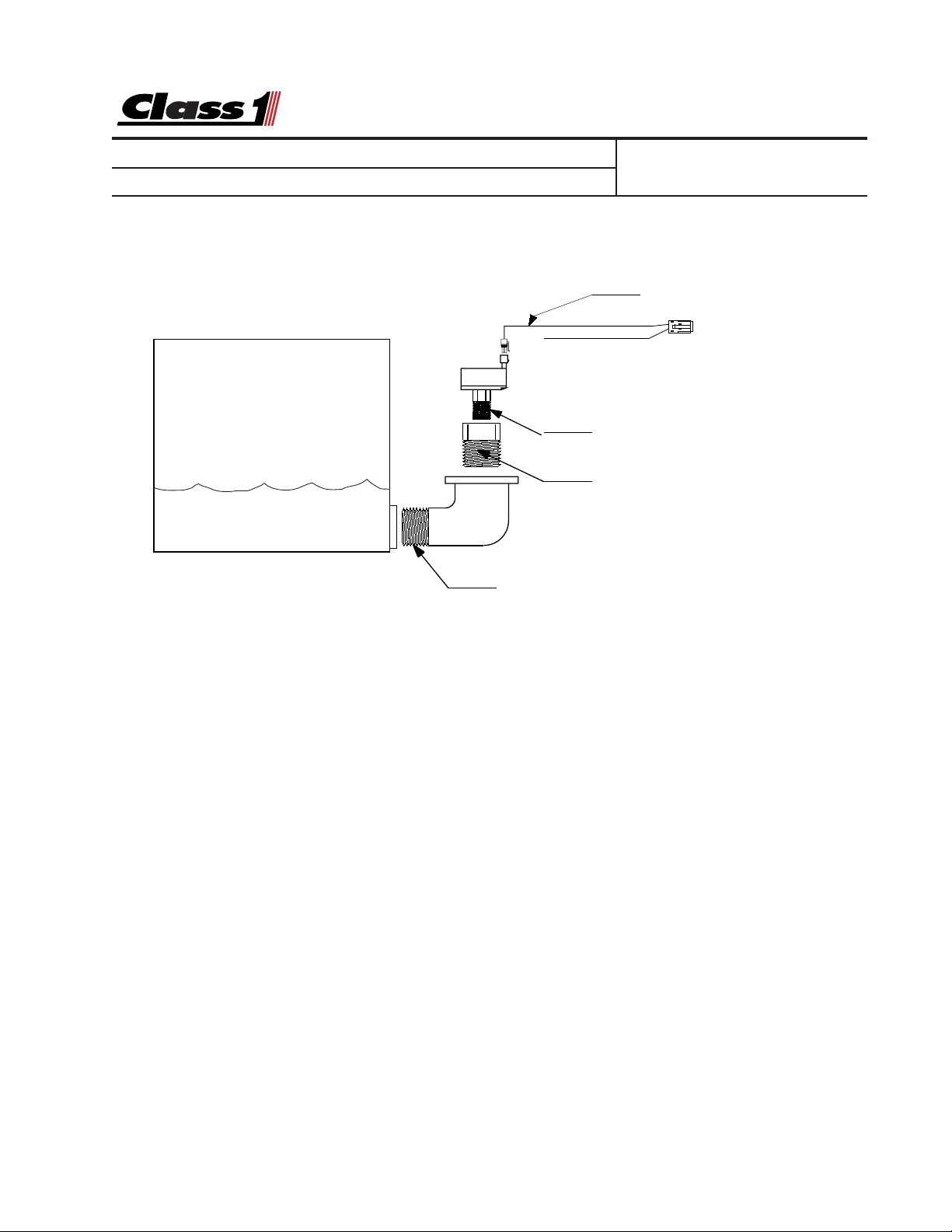
Tank Level Gauge
Transducer Installation
Engineering
Standards
Engineering Standard Number
C1-105593
Harness
5’ PN 105597
10’ PN105598
20’ PN105599
FLUID TANK
3/4 NPT Elbow (OEM)
The transducer must be mounted vertically as depicted to insure an accurate and reliable reading.
This will also prevent damage to the transducer from freezing.
Harnesses are supplied with a cable to connect the transducer.
Loose wires with appropriate terminals for the outputs and ground are including to facilitate installation.
Pressure Transducer
1/4 NPT
Adapter 3/4-1/4 NPT Bushing (OEM)
Foam adapter is supplied when a
foam level system is ordered.
The transducer measures the column of water in the tank above the opening of the elbow.
When calibrating for a full tank it is important that the tank not be overfilled. If the fill opening or
tank vent is above the transducer, care should be taken not to have water in this area when
calibrating the tank level gauge. The transducer should never be mounted in the sump area
because of sludge and potential inaccuracies in calibration.
Mount a 3/4 NPT elbow just off the bottom of the tank, enough to keep sediment out of the
elbow and transducer (PN 102162). Attach a 3/4 to 1/4 NPT adapter (supplied for foam) to the
elbow and mount the transducer to that. The elbow and adapter need to be installed so that
the transducer is mounted vertically.
E:\MANUALS\DIGITAL\TANKLEVEL\NEW TANK LEVEL_ESN.P65_05062001
page 2 of 5 pages
Page 3

Engineering
ISO 9001 CERTIFIED
Name
Identifier OEM Installation and Calibration
Four Output Tank Level
Standards
Engineering Standard Number
C1-105593
The module is waterproof and can be mounted in almost any location. Avoid areas of Extremely high temperature (above 75 deg C) and/or high vibration.
Connector information:
Connector Terminal Lock
Deutsch DTM06-12SA 0462-201-20141(18-24 Ga.) WM-12S
1062-20-0122 (10-16 Ga.)
1 1/4 indication output 7 NC
2 NC 8 Transducer +5 VDC output
3 N C 9 Full indication output
4 3/4 indication output 10 1/2 indication output
5 Transducer Signal input 11 Transducer Ground output
6 NC 12 Ground
#10 Ring terminal Output Driver P ow er
LED Status
Red PWR System Po w er and Ground OK
Amber BU S Driver Power OK
Green COM Flashes 8X on power up and then steady
E:\MANUALS\DIGITAL\TANKLEVEL\NEW TANK LEVEL_ESN.P65_05062001
page 3 of 5 pages
Page 4

ISO 9001 CERTIFIED
Name
Four Output Tank Level
Identifier OEM Installation and Calibration
Pressed
Not Pressed
OFF
ON
Flash
LED3LED2
EMPTY
FULL
SW2
FULL
SW2
FULL
SW2
FULL
SW2
FULL
SW2
FULL
SW2
FULL
SW2
FULL
SW2
FULL
SW2
CALIBRATE
CALIBRATE
CALIBRATE
CALIBRATE
CALIBRATE
CALIBRATE
CALIBRATE
CALIBRATE
CALIBRATE
SW3
LED3LED2
EMPTY
SW3
LED3LED2
EMPTY
SW3
LED3LED2
EMPTY
SW3
LED3LED2
EMPTY
SW3
LED3LED2
EMPTY
SW3
LED3LED2
EMPTY
SW3
LED3LED2
EMPTY
SW3
LED3LED2
EMPTY
SW3
E:\MANUALS\DIGITAL\TANKLEVEL\NEW TANK LEVEL_ESN.P65_05062001
Press and hold both switches
for two (2) seconds.
Both LED's will illuminate.
Release both switches.
Both LED's will Flash at
the same time.
Press the switch for the
calibration you will perform
first. (Full or Empty)
You can start with either, this
example will use FULL.
The FULL LED will start to
flash rapidly. The EMPTY
LED should turn off.
With the tank filled, press the
FULL calibration switch for 1/2
second.
The FULL LED will turn on steady
for 1/2 second and then turn off.
The EMPTY LED will start flashing
at a rate of once per second.
Press the EMPTY switch. The flash
rate will increase.
Empty the tank and then press the
EMPTY switch again.
The EMPTY LED will come on steady
for 1/2 second and then both LED's will
turn on steady and then turn off.
The outputs will indicate the current
tank level.
Level Calibration is complete.
Engineering
Standards
Engineering Standard Number
C1-105593
CONN1
AMS
8-24-2000
REVB
Z1
U9
P.N. 105299
U12
U10
R20 R21R22
R23 R13 R12 R11R10
R14
FULL
SW2
CALIBRATE
U6
LED3LED2
EMPTY
U11
C3
SW3
C4
U4
F1
R17
U5
Level Calibration
For Level Calibration, enter the following password
EMPTY EMPTY EMPTY EMPTY EMPTY FULL EMPTY FULL
Press and hold both calibration switches for two (2)
seconds. Both calibration LED’ s will illuminate .
Release both switches. Both calibration LED’ s will
flash as well as the Full output and the 1/4 tank output.
With the tank either empty or full, press
the switch associated with the condition of the tank (empty
or full) that you are calibrating. The LED, Output and the
COM LED will come on for 1/2 second and then go out.
The opposite calibration LED , output and the COM LED will
flash at a rate of once per second.
Press the switch associated with the flashing calibration LED . The flash r ate will increase.
Either empty or fill the tank as appropriate. Allow
the water level to stabilize and then press the calibration
switch under the flashing LED. (hold for 1/2 second) Both
calibration LED’ s will come on steady , The outputs will indicate the current tank level and the COM LED will return to a
steady green.
LED1
U13
D2
R6 R7
FT3
+
R9
R8
C5
C15
D3
C2
U2
C12
C10
U1
page 4 of 5 pages
R5
R3 R2
TP1
TP2
TP3
C1
XT1
C11
Page 5

ISO 9001 CERTIFIED
LED3LED2
SW2
SW3
EMPTY
FULL
CALIBRATE
LED3LED2
SW2
SW3
EMPTY
FULL
CALIBRATE
LED3LED2
SW2
SW3
EMPTY
FULL
CALIBRATE
LED3LED2
SW2
SW3
EMPTY
FULL
CALIBRATE
LED3LED2
SW2
SW3
EMPTY
FULL
CALIBRATE
LED3LED2
SW2
SW3
EMPTY
FULL
CALIBRATE
LED3LED2
SW2
SW3
EMPTY
FULL
CALIBRATE
Pressed
Not Pressed
OFF
ON
Flash
Name
Four Output Tank Level
Identifier OEM Installation and Calibration
Engineering
Standards
Engineering Standard Number
C1-105593
Volume Calibration
For V olume Calibration, enter the following pass word EMPTY FULL EMPTY FULL EMPTY EMPTY EMPTY EMPTY
Press and hold both switches for two seconds. Both LED’s will illuminate.
Release both switches. Both LED’s will
be on steady. Ensure that the tank is full.
Press the full switch and hold until the
EMPTY LED turns OFF . You can start with
either an empty or a full tank. This example uses the a full tank to start with.
The FULL value has been stored
The FULL LED will be flashing rapidly.
Drain the tank to the 3/4 full mark Press
and hold the FULL switch until the EMPTY
LED turns ON.
The 3/4 value has been stored.
Both LED’s are now flashing slo wly. Drain
the tank to the 1/2 full level. Press and
hold both switches until the FULL LED
turns OFF .
The 1/2 tank value has been stored.
The empty LED will be slowly flashing.
Drain the tank to the 1/4 level. Press and
hold the EMPTY switch until the FULL
LED turns ON.
The 1/4 tank value has been stored.
The EMPTY LED will be flashing rapidly.
Press the EMPTY switch until the LED
stops flashing.
The calibration procedure is complete.
Both LED’s should be OFF.
The COM LED will turn off.
The COM LED wll flash. The Full and !/4 outputs will be
steady ON.
The COM LED will be flashing rapidly. The first volume
point is now stored. The output for the 3/4 calibration
point will turn ON.
The current tank level is stored and associated with 3/4
full level.
The 1/2 tank output will turn on and the COM LED will
flash slowly.
The current tank level is stored and associated with half
tank volume.
The output for the 1/4 tank calibration point will tur n on
and the COM LED will continue flashing at the slow rate.
The 1/4 tank value is stored.
The COM LED will flash quickly. Empty the tank the 1/4
output will be flashing rapidly. Press and hold the switch
under the EMPTY LED until it remains steady. The current transducer value is stored and associated with empty .
Outputs will now indicate the current tank level and the
COM LED will be steady.
E:\MANUALS\DIGITAL\TANKLEVEL\NEW TANK LEVEL_ESN.P65_05062001
page 5 of 5 pages
 Loading...