

Page 1
TECHNICAL PRODUCT DATASHEET
Sentry Pressure Governor
FORM-ENG-0018 REV A 06-02-03
ISO 9001 CERTIFIED
607 NW 27th Ave
Phone: (352) 629-5020 or 800-533-3569
Ocala, FL 34475
Fax: (352)-629-2902
SUITABLE FOR EXTER NAL DISTRIBUTION
with Twister Control
P/N 3045-101-00-CL1
P/N 3045-102-00-CL1
Page 2

FORM-ENG-0018 REV A 05-27-03
607 NW 27th Ave
Ocala, FL 34475
Ph: 352-629-5020 or 1-800-533-3569
Fax : 352-629-2902 or 1-800-520-3473
PRODUCT GROUP
PRODUCT
SENTRY PRESSURE GOVERNOR
TECHNICAL DATA SHEET
THROTTLE CONTROL
P/N 3045-101-00-CL1, 3045-102-00-CL1 REV
PAGE
DATE
BY AMS
1 OF 36
6/19/2014
1.02
1. REVISION LOG ........................................................................................................................................... 3
2. SYSTEM OVERVIEW .................................................................................................................................. 4
2.1. SYSTEM PART NUMBERS ........................................................................................................................... 4
2.2. WIRING DETAIL ......................................................................................................................................... 4
3. OVERVIEW OF THE SENTRY GOVERNOR .............................................................................................. 5
3.1. MODE AND INTERLOCK INDICATORS (SENTRY) ........................................................................................... 6
3.2. PUMP DISCHARGE PRESSURE DISPLAY (SENTRY) ....................................................................................... 6
3.3. PUMP INTAKE PR ESSURE DISPLAY (SENTRY) .............................................................................................. 6
3.4. MODE, PRESET, AND IDLE BUTTONS (SENTRY) .......................................................................................... 6
3.4.1. IDLE ................................................................................................................................................... 6
3.4.2. PRESET 1 ......................................................................................................................................... 6
3.4.3. PRESET 2 ......................................................................................................................................... 7
3.4.4. MODE ................................................................................................................................................ 7
3.5. “SOFT” BUTTONS (SENTRY) ...................................................................................................................... 7
3.6. INFORMATION DISPLAYS (SENTRY) ............................................................................................................ 7
3.6.1. Engine RPM display .......................................................................................................................... 7
3.6.2. Battery voltage display ...................................................................................................................... 7
3.6.3. Coolant temperature display ............................................................................................................. 7
3.6.4. Oil pressure display ........................................................................................................................... 7
3.6.5. Transmission temperature display .................................................................................................... 7
3.6.6. Fuel economy display ........................................................................................................................ 7
3.7. READY INDICATOR (TWISTER) ................................................................................................................... 8
3.8. ACTIVE INDICATOR (TWISTER) ................................................................................................................... 8
3.9. CONTROL KNOB (TWISTER) ....................................................................................................................... 8
3.10. IDLE BUTTON (TWISTER) ........................................................................................................................... 8
4. OPERATION ................................................................................................................................................ 9
4.1. INITIALIZATION .......................................................................................................................................... 9
4.2. OPERATING MO D E SELECTION ................................................................................................................. 10
4.2.1. Throttle mode .................................................................................................................................. 10
4.2.2. Pressure mode ................................................................................................................................ 11
4.2.3. Pressure mode control parameters ................................................................................................. 12
4.3. REQUIRED INTERLOCKING ....................................................................................................................... 13
4.4. PRESET BUTTON OPERATION ................................................................................................................ 13
4.5. IDLE BUTTON OPERATION ...................................................................................................................... 13
5. WARNING AND ERROR MESSAGES ..................................................................................................... 14
5.1. FIRST LEVEL MESSAGE INFORMATION (OPERATOR) ................................................................................... 14
5.2. SECOND LEVEL MESSAGE INFORMATION (TECHNICIAN) ............................................................................. 15
5.3. LIST OF WARNING/ER R O R MESSAGES ...................................................................................................... 15
5.3.1. Intake or Discharge Sensor Fault .................................................................................................... 18
5.3.2. Water Supply Insufficient, Discharge Pressure Less Than 30 Psi, and Critical: Sentry In Stand By.
Check Water Source ...................................................................................................................................... 18
5.3.3. Unable To Maintain Discharge Pressure......................................................................................... 18
5.3.4. Discharge Pressure Has Increased More Than 50 Psi Since Setting Rpms .................................. 18
5.3.5. Communication with engine is lost .................................................................................................. 19
6. SENTRY SETUP MENUS .......................................................................................................................... 20
6.1. ENGINE COMPATIBILITY ........................................................................................................................... 20
6.2. ENTER THE SETUP MENU ........................................................................................................................ 20
Page 3

FORM-ENG-0018 REV A 05-27-03
607 NW 27th Ave
Ocala, FL 34475
Ph: 352-629-5020 or 1-800-533-3569
Fax : 352-629-2902 or 1-800-520-3473
PRODUCT GROUP
PRODUCT
SENTRY PRESSURE GOVERNOR
TECHNICAL DATA SHEET
THROTTLE CONTROL
P/N 3045-101-00-CL1, 3045-102-00-CL1 REV
PAGE
DATE
BY AMS
2 OF 36
6/19/2014
6.2.1. Menu soft buttons ............................................................................................................................ 20
6.3. INFO MENU ........................................................................................................................................... 21
6.3.1. Reset the Pump Hours .................................................................................................................... 21
6.3.2. Reset the Auxiliary Hours ................................................................................................................ 21
6.3.3. Zero Calibrate the pressure sensors ............................................................................................... 21
6.3.4. Set Factory Defaults ........................................................................................................................ 21
6.3.5. Autoscale Analog Output ................................................................................................................. 22
6.4. USER MENU .......................................................................................................................................... 22
6.4.1. Change the unit of measure ............................................................................................................ 23
6.4.2. Change the Preset RPM 1 .............................................................................................................. 23
6.4.3. Change the Preset Pressure 1 ........................................................................................................ 23
6.4.4. Change the Preset RPM 2 .............................................................................................................. 23
6.4.5. Change the Preset Pressure 2 ........................................................................................................ 23
6.4.6. Change the Display Brightness (day mode) .................................................................................... 23
6.4.7. Change the Display Brightness (night mode) .................................................................................. 23
6.4.8. Round pressure ............................................................................................................................... 23
6.4.9. Change the Display Mode (Day or Night)........................................................................................ 23
6.5. OEM 1 MENU ......................................................................................................................................... 24
6.5.1. Set the Warning Alert Tone ............................................................................................................. 24
6.5.2. Sensitivity (pressure) ....................................................................................................................... 24
6.5.3. First Operating Mode ....................................................................................................................... 24
6.5.4. Intake Sensor Range ....................................................................................................................... 24
6.5.5. Discharge Sensor Range ................................................................................................................ 25
6.5.6. Inhibit RPM Presets ......................................................................................................................... 25
6.5.7. Warning Source ............................................................................................................................... 25
6.5.8. Coolant Temperature Warning (USER) ........................................................................................... 25
6.5.9. Coolant Temperature Critical (USER) ............................................................................................. 25
6.5.10. Oil Pressure Warning (USER)..................................................................................................... 25
6.5.11. Oil Pressure Critical (USER) ....................................................................................................... 25
6.5.12. Intake Threshold ......................................................................................................................... 25
6.6. OEM 2 MENU ......................................................................................................................................... 26
6.6.1. Battery Voltage Range .................................................................................................................... 26
6.6.2. Engine Control Method .................................................................................................................... 26
6.6.3. Auto Mode ....................................................................................................................................... 26
6.6.4. Idle Voltage ...................................................................................................................................... 27
6.6.5. Idle Engine Speed (RPM) ................................................................................................................ 27
6.6.6. Maximum Engine Speed (RPM) ...................................................................................................... 27
6.6.7. CAN Source ID ................................................................................................................................ 27
6.6.8. Pressure Time-Out (Seconds) ......................................................................................................... 27
6.6.9. Governor Gain (RPM per volt) ......................................................................................................... 28
6.6.10. Pressure Gain (pressure change per step) ................................................................................. 28
6.6.11. DITHER (Engine handshake)...................................................................................................... 28
6.6.12. LAG (PSI/kPa/Bar) ...................................................................................................................... 28
6.6.13. BCM1 VER (Body Control Message 1 version) .......................................................................... 28
6.6.14. Scania Mode (Scania governor type) .......................................................................................... 28
6.7. FACT MENU .......................................................................................................................................... 29
6.7.1. Positive Twister Direction ................................................................................................................ 29
6.7.2. Display Fuel Economy ..................................................................................................................... 29
6.7.3. Display Transmission Temperature ................................................................................................. 29
6.7.4. Display Oil Pressure ........................................................................................................................ 29
1.02
7. CONFIGURATION ..................................................................................................................................... 30
7.1. CONFIGURE THE IDLE VOLTAGE AND GAIN SETTING USING AUTO SCALE (ANALOG ENGINES).................... 30
7.2. CONFIGURE THE TWISTER FOR OPERATION WITH THE SENTRY (MASTER) .................................................. 30
7.3. CONFIGURE THE TWISTER FOR OPERATION WITH THE SENTRY (SLAVE) ..................................................... 31
Page 4
FORM-ENG-0018 REV A 05-27-03
Rev
Date
Changes
607 NW 27th Ave
Ocala, FL 34475
Ph: 352-629-5020 or 1-800-533-3569
Fax : 352-629-2902 or 1-800-520-3473
PRODUCT GROUP
PRODUCT
SENTRY PRESSURE GOVERNOR
TECHNICAL DATA SHEET
THROTTLE CONTROL
P/N 3045-101-00-CL1, 3045-102-00-CL1 REV
PAGE
DATE
BY AMS
3 OF 36
6/19/2014
1.02
8. MOUNTING & INSTALLATION ................................................................................................................. 32
8.1. PANEL CUTOUT DIMENSIONS (SENTRY) .................................................................................................... 32
8.2. PANEL CUTOUT DIMENSIONS (TWISTER) .................................................................................................. 32
9. CONNECTOR DESCRIPTION................................................................................................................... 33
9.1. SENTRY CONNECTORS ......................................................................................................................... 33
9.2. PRESSURE SENSOR CONNECTOR ............................................................................................................ 34
9.3. TWISTER CONNECTOR ............................................................................................................................ 34
10. TECHNICAL DETAILS .............................................................................................................................. 35
1. Revision Log
1.00
1.01
1.02
2/19/2013 Initial revision
6/19/2014 Updated function of blue LED on Twister.
7/16/2014 Added new factory menu options for version 1.5g
Product specifications in this ma n u al are subject to change without notice.
Page 5
FORM-ENG-0018 REV A 05-27-03
607 NW 27th Ave
Ocala, FL 34475
Ph: 352-629-5020 or 1-800-533-3569
Fax : 352-629-2902 or 1-800-520-3473
PRODUCT GROUP
PRODUCT
2. System Overvi ew
2.1. System part numbers
Sentry Pressure Governor system kit, vertical 599-00010-001
Sentry Pressure Governor system kit, horizontal 599-00010-002
Kit includes
Sentry Pressure Governor, vertical QTY-1 3045-101-00-CL1
OR Sentry Pressure Governor, horizontal QTY-1 3045-102-00-CL1
Twister Control Knob QTY-1 119970
Sentry system harness QTY-1 513-00019
Sentry Label, vertical QTY-1 122482
OR Sentry Label, horizontal QTY-1 122481
Transducer 0-300 PSI QTY-2 113557
Optional items
Transducer 0-600 PSI 117179
Documentation (available from Class 1’s website - www.class1.com)
Engine compatibility guide 117686
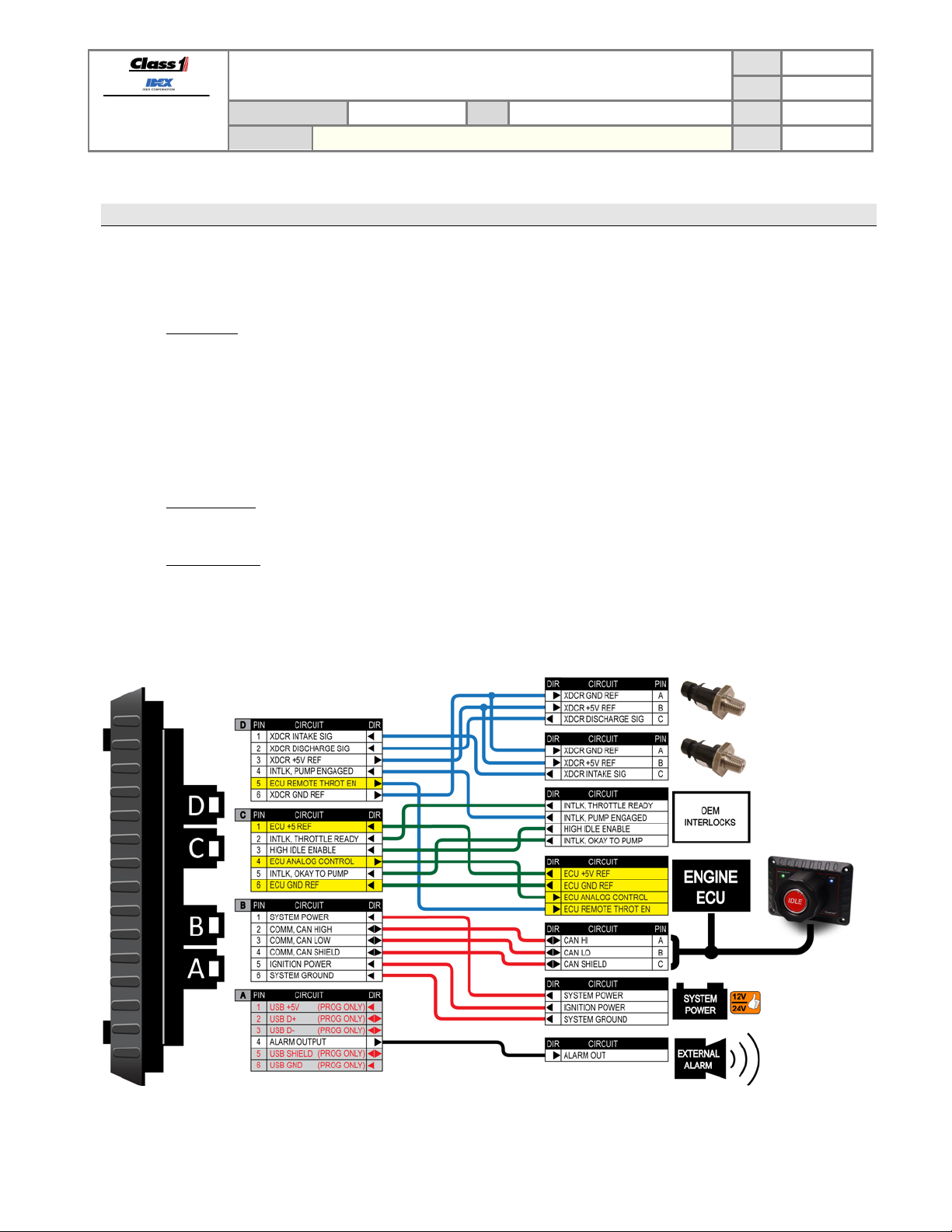
2.2. Wiring detail
Below is the point-to-point wiring of the Sentry. The circuits with the yellow background are for analog control of the
engine ECU and are optional.
TECHNICAL DATA SHEET
THROTTLE CONTROL
SENTRY PRESSURE GOVERNOR
P/N 3045-101-00-CL1, 3045-102-00-CL1 REV
PAGE
DATE
BY AMS
4 OF 36
6/19/2014
1.02
Figure 1. Wiring detail.
Page 6
FORM-ENG-0018 REV A 05-27-03
607 NW 27th Ave
Ocala, FL 34475
Ph: 352-629-5020 or 1-800-533-3569
Fax : 352-629-2902 or 1-800-520-3473
PRODUCT GROUP
PRODUCT
TECHNICAL DATA SHEET
THROTTLE CONTROL
SENTRY PRESSURE GOVERNOR
3. Overvi ew of the Sentry Governor
The Sentry Governor (p/n 3045-101-00-CL1 vertical, p/n 3045-102-00-CL1 horizontal) is an SAE
J1939 Controller Area Network (CAN) device that controls engine speed using data
communications direc t l y to the engine ECU or through with an analog control signal. By operating
on the J1939 network, the governor is able to monitor engine RPM and other pertinent data directly
from the engine ECU. Engine information is available directly so that NFPA required
instrumentation is delivered through a single unit saving panel space and delivering engine specific
warnings as determined by each engine manufacturer.
Control algorithms are optimized to take advantage of the J1939 CAN data to yield crisp and
accurate control of engine and subsequently pump speed and pressure output.
For engines that may not support the data link control, an analog output signal is available to
provide precise control of the engine speed and pressure.
PAGE
DATE
P/N 3045-101-00-CL1, 3045-102-00-CL1 REV
BY AMS
5 OF 36
6/19/2014
1.02
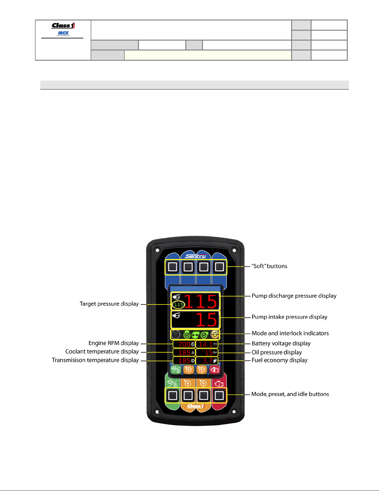
The SENTRY saves pump panel space by incorporating easy to read numeric displays for Pump Intake
pressure, Pump Discharge pressure, and engine RPM in accordance with NFPA standards.
Figure 2. Sentry controls and indicators.
Page 7
FORM-ENG-0018 REV A 05-27-03
607 NW 27th Ave
Ocala, FL 34475
Ph: 352-629-5020 or 1-800-533-3569
Fax : 352-629-2902 or 1-800-520-3473
PRODUCT GROUP
PRODUCT
SENTRY PRESSURE GOVERNOR
TECHNICAL DATA SHEET
THROTTLE CONTROL
P/N 3045-101-00-CL1, 3045-102-00-CL1 REV
PAGE
DATE
BY AMS
6 OF 36
6/19/2014
1.02
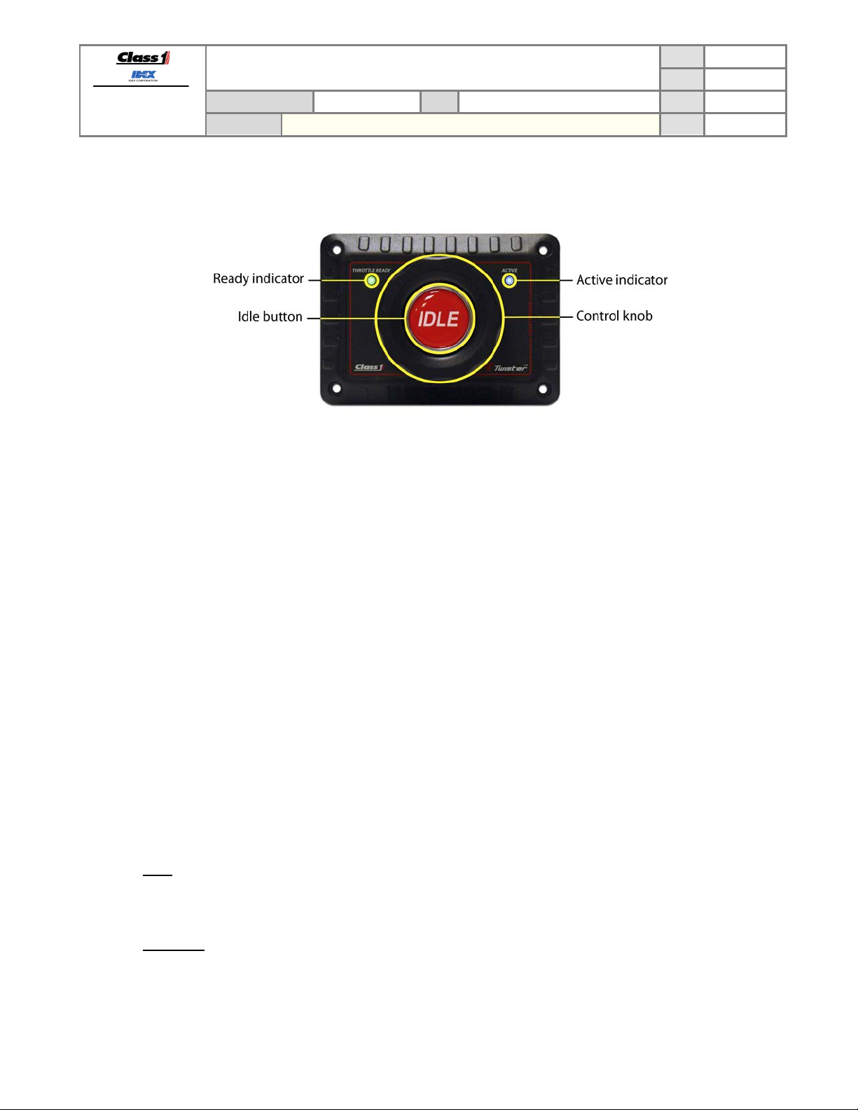
Figure 3. Twister controls and indicato rs.
3.1. Mode and Interlock indicators (Sentry)
Green icons indicate the status of the three (3) interlocks: throttle ready, pump engaged, and okay to pump.
The mode indicators consist of two (2) icons to show the governor’s current operating mode. The PRESSURE MODE
ICON (yellow) indicates the governor is operating in pressure mode and the RPM MODE ICON (blue) indicates the
governor is operating in throttle mode. When both icons are OFF the governor is in idle mode (standby).
3.2. Pump discharge pressure display (Sentry)
The pump discharge pressure display shows the pressure as determined by the discharge pressure sensor. By
default, this display only shows positive pressure in pounds per square inch (PSI), but it may be set up to display in
metric units (see section 6.4.1).
3.3. Pump intake pressure display (Sentry)
The pump intake pressure display shows the pressure as determined by the intake pressure sensor. By default, this
display shows positive pressure in pounds per squ are inch (PSI) and negative pressure (vacuum) in inches of
mercury (inHg), but it may be set up to display in metric units (see section 6.4.1).
3.4. Mode, Preset, and Idle buttons (Sentry)
The four (4) control buttons are color coded and labeled for easy identification.
3.4.1. IDLE
The IDLE switch (red) forces the governor to idle mode (standby). Pressing and holding this button for one
second while in rpm mode or pressure mode will cause the engine to ramp down to its idle position.
3.4.2. PRESET 1
The PRESET 1 button (orange) sets the governor to the configured preset 1 engine RPM while in throttle mode, or
preset pressure while in pressure mode.
Page 8

FORM-ENG-0018 REV A 05-27-03
607 NW 27th Ave
Ocala, FL 34475
Ph: 352-629-5020 or 1-800-533-3569
Fax : 352-629-2902 or 1-800-520-3473
PRODUCT GROUP
PRODUCT
3.4.3. PRESET 2
The PRESET 2 button (orange) sets the governor to the configured preset 2 engine RPM while in throttle mode, or
preset pressure while in pressure mode.
3.4.4. MODE
The MODE button (green) sets the governor to either throttle mode (RPM) or pressure mode (PSI). The correct
interlocks must be present for the system to begin governor operation: throttle ready for RPM mode, throttle ready,
pump engaged, and okay to pump for PSI mode.
3.5. “Soft” buttons (Sentry)
The four (4) soft buttons have functions based on the current operating mode and/or warning messages display.
These buttons are typically used for menu navigation, configuration, and warning message evaluations.
3.6. Information displays (Sentry)
The Sentry has six (6) information displays.
3.6.1. Engine RPM display
The engine RPM display shows the current engine RPM as reported by the Electronic Engine Controller 1 (EEC1)
SAE J1939 network data message transmitted by the vehicle ECU.
3.6.2. Battery voltage display
The battery voltage display shows the current system voltage as determined by the voltage present on pin 1 of
connector B.
3.6.3. Coolant temperature display
The coolant temperature display shows the current coolant system temperature as reported by the Electronic
Engine Temperature 1 (ET1) SAE J1939 network data message transmitted by the vehicle ECU. The temperature
will be displayed in degrees Fahrenheit (°F) or degrees Celsius (°C) dependent on the unit of measure configured
in the setup menu (see section 6.4.1
3.6.4. Oil pressure display
The oil pressure display shows the current oil pressure as reported by the engine Fluid Level/Pressure 1 (EFL/P1)
SAE J1939 network data message transmitted by the vehicle ECU. The pressure will be displayed in PSI, kPa, or
Bar dependent on the unit of measure configured in the setup menu (see section 6.4.1
3.6.5. Transmission temperature display
The transmission temperature display shows the transmission oil temperature as reported by the Transmission
Fluids 1 (TRF1) SAE J1939 network data message transmitted by the vehicle TCU. The temperature will be
displayed in degrees Fahrenheit (°F) or degrees Celsius (°C) dependent on the unit of measure configured in the
setup menu (see section 6.4.1
3.6.6. Fuel economy display
The fuel economy display shows the current fuel usage per hour as reported by the Fuel Economy, Liquid (LFE1)
SAE J1939 network data message transmitted by the vehicle ECU. The fuel economy will be displayed in gallons
per hour (G/h) or liters per hour (L/h) dependent on the unit of measure configured in the setup menu (see section
6.4.1
TECHNICAL DATA SHEET
SENTRY PRESSURE GOVERNOR
THROTTLE CONTROL
PAGE
DATE
P/N 3045-101-00-CL1, 3045-102-00-CL1 REV
BY AMS
7 OF 36
6/19/2014
1.02
Page 9

FORM-ENG-0018 REV A 05-27-03
607 NW 27th Ave
Ocala, FL 34475
Ph: 352-629-5020 or 1-800-533-3569
Fax : 352-629-2902 or 1-800-520-3473
3.7. Ready indicator (Twister)
The green READY indicator shows the status Sentry throttle ready interlock.
3.8. Active indicator (Twister)
The blue READY indicator indicates that the Twister is ready to control the Sentry. This is mainly used with dualgovernor applications to indicate which governor is active for user operation.
3.9. Control knob (Twister)
The control knob is the operator’s interface for controlling the Sentry’s engine speed (throttle mode) and target
pressure (pressure mode). The control knob can be configured to increase engine speed/target pressure with
clockwise or counter-clockwise rotation (see section 6.7.1).
3.10. Idle button (Twister)
The Twister’s idle button performs the same task as the idle button on the Sentry. Press and hold this button for one
second while in rpm mode or pressure mode to force the engine to ramp down to its idle position.
PRODUCT GROUP
PRODUCT
TECHNICAL DATA SHEET
THROTTLE CONTROL
SENTRY PRESSURE GOVERNOR
P/N 3045-101-00-CL1, 3045-102-00-CL1 REV
PAGE
DATE
BY AMS
8 OF 36
6/19/2014
1.02
Page 10
FORM-ENG-0018 REV A 05-27-03
607 NW 27th Ave
Ocala, FL 34475
Ph: 352-629-5020 or 1-800-533-3569
Fax : 352-629-2902 or 1-800-520-3473
4. Operation
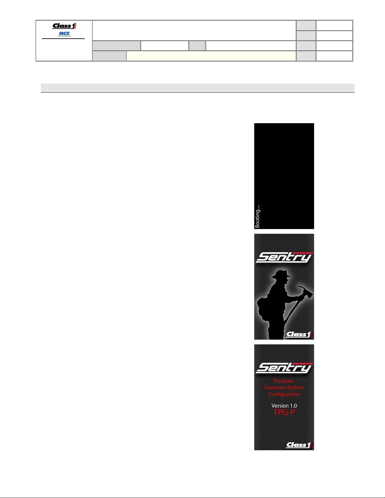
4.1. Initialization
The SENTRY has a six (12) second power initialization cycle and during this time the display will show:
The SENTRY displays a black screen with the word
“Booting….” For 4 seconds after a power cycle.
PRODUCT GROUP
PRODUCT
SENTRY PRESSURE GOVERNOR
TECHNICAL DATA SHEET
THROTTLE CONTROL
P/N 3045-101-00-CL1, 3045-102-00-CL1 REV
PAGE
DATE
BY AMS
9 OF 36
6/19/2014
1.02
The SENTRY shows the Sentry logo for the next 4
seconds.
The Sentry shows the version and configuration for the
last 4 seconds. The last letter of this display indicates the
configured control method of the SENTRY.
TPG-C – CFPG control method
TPG-P – PGN0 control method
TPG-A – Analog control method
TPG-S – Scania control method
TPG-D – Mercedes control method
SLAVE – Second Sentry device
(See section 6.6.2 for engine configuration).
After the initialization the SENTRY begins normal
operation.
Page 11
FORM-ENG-0018 REV A 05-27-03
607 NW 27th Ave
Ocala, FL 34475
Ph: 352-629-5020 or 1-800-533-3569
Fax : 352-629-2902 or 1-800-520-3473
4.2. Operating mode selection
The SENTRY has two operating modes: throttle mode (RPM) and pressure mode (PSI).
There is no variation in engine RPM or pump pressure when changing between throttle mode and pressure mode.
Pressure mode is the desired operating mode because it offers protection from pressure changes that could
injure personnel.
4.2.1. Throttle mode
Throttle mode (RPM) maintains a set engine RPM and will not deviate until the operator changes the RPM with
the control switches on the SENTRY. (Proper interlocking is required for normal operation – refer to Required Interlocking
section 4.3)
Throttle mode is typically used when…
PRODUCT GROUP
PRODUCT
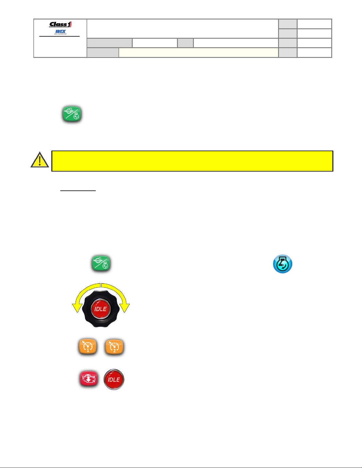
Press the MODE button to select an operating mode. An operating mode will only be activated if the
required interlock(s) are in place (see section 4.3).
• priming the pump
• connected to a stand pipe
TECHNICAL DATA SHEET
THROTTLE CONTROL
SENTRY PRESSURE GOVERNOR
P/N 3045-101-00-CL1, 3045-102-00-CL1 REV
• the water supply pressure stability is questionable
• acting as a relay pumper
PAGE
DATE
BY AMS
10 OF 36
6/19/2014
1.02
Press the MODE button to select throttle mode. The RPM
mode indicator LED will illuminate blue.
Rotate the Twister knob in the INCREASE direction to
increase or the DECREASE direction to decrease the engine
RPM set point. The direction of increase can be set to
clockwise or counter-clockwise (see section 6.7.1).
Press a PRESET button to set the engine speed to the
configured preset RPM - as long as the pump pressure is
less than 10 PSI (see section 4.4).
Configure the throttle mode presets through the USER
Menu (see section 6.4.2 and 6.4.4)
Press the IDLE button (on Sentry or Twister) at any time to
set the SENTRY back to standby. Both mode indicator LEDs
will turn off when the engine speed reaches idle (see section
4.5).
Page 12

FORM-ENG-0018 REV A 05-27-03
PRESET
607 NW 27th Ave
Ocala, FL 34475
Ph: 352-629-5020 or 1-800-533-3569
Fax : 352-629-2902 or 1-800-520-3473
4.2.2. Pressure mode
Pressure mode maintains a set pump pressure by monitoring the discharge pressure transducer and modifying the
pump speed by adjusting the engine RPM. The operator can modify the set pump pressure with the control
switches on the SENTRY.
Pressure mode affords the most safety to the operator by not allowing potentially hazardous pressure spikes. The
SENTRY will maintain the set pump pressure even when discharge lines are actively opened and closed as long as
the water supply is sufficient. T he SENTRY will automatically increase engine speed when pump pressure has
decreased due to discharge lines being opened. The increase in engine speed will return the pump pressure to the
desired set pressure (and vice-versa when discharge lines are closed).
PRODUCT GROUP
PRODUCT
SENTRY PRESSURE GOVERNOR
PAGE
TECHNICAL DATA SHEET
THROTTLE CONTROL
(Proper interlocking is required for normal operation – refer to Required Interlocking section 4.3)
Press the MODE button to select pressure mode. The
PSI mode indicator LED will illuminate yellow.
It may be necessary to press the MODE switch twice
depending on the configured first mode (see section 6.5.3).
P/N 3045-101-00-CL1, 3045-102-00-CL1 REV
DATE
BY AMS
11 OF 36
6/19/2014
1.02
Rotate the Twister knob in the INCREASE direction to
increase or the DECREASE direction to decrease the
pressure set point. The direction of increase can be set to
clockwise or counter-clockwise (see section 6.7.1). The
target pressure will be displayed in the target pressure
display.
Press a
configured preset. The SENTRY will adjust the engine
RPM to maintain the preset pressure value (see section
4.4).
Configure the pressure mode preset through the Setup
Menu (see section 6.4.3 and 6.4.5).
Press the IDLE switch at any time to set the SENTRY back
to standby. Both mode indicator LEDs will turn off when
the engine speed reaches idle (see section 4.5).
button to set the pump pressure to the
Page 13

FORM-ENG-0018 REV A 05-27-03
607 NW 27th Ave
Ocala, FL 34475
Ph: 352-629-5020 or 1-800-533-3569
Fax : 352-629-2902 or 1-800-520-3473
PRODUCT GROUP
PRODUCT
4.2.3. Pressure mode control parameters
There are three control parameters which can be modified to improve pressure mode performance: pressure
sensitivity, pressure time-out, and pressure gain.
CONTROL
PARAMETER
Pressure sensitivity
Pressure time-out
Pressure gain
TECHNICAL DATA SHEET
THROTTLE CONTROL
SENTRY PRESSURE GOVERNOR
Controls how much difference between the target pressure
and actual pressure that is allowed before the SENTRY
actively adjusts the engine speed to bring the discharge
pressure back to the target pressure.
The engine speed will be commanded to the idle RPM when
the discharge pressure drop s below 30 PSI (and only after
the discharge pressure had been above 50 PSI) for the
number of seconds configured. The alarm will sound and the
OPERATOR CMD warning will be shown in the display
window (see section 5).
The pressure change requested with each Twister control
click in the INCREASE or DECREASE direction.
PAGE
DATE
P/N 3045-101-00-CL1, 3045-102-00-CL1 REV
BY AMS
12 OF 36
6/19/2014
1.02
DESCRIPTION DEFAULT SECTION
6 PSI 6.5.2
3 Seconds 6.6.8
3 PSI 6.6.10
Page 14

FORM-ENG-0018 REV A 05-27-03
THROTTLE READY interlock
PUMP ENGAGED interlock
OKAY TO PUMP
607 NW 27th Ave
Ocala, FL 34475
Ph: 352-629-5020 or 1-800-533-3569
Fax : 352-629-2902 or 1-800-520-3473
4.3. Required interlocking
The SENTRY requires interlocks before engine control operations are permitted. The SENTRY provides two
interlock inputs that allow easy separation of pumping operations and throttle/high idle operations through two inputs
dedicated as system interlocks: THROTTLE READY (pin 2 of connector C) and PUMP ENGAGED (pin 4 of connector
D). These interlock inputs are activated when system power is applied (positive polarity).
The OEM is responsible for creating safe and effective interlocking routines.
The SENTRY uses green icons to indicate the status of the interlock s.
PRODUCT GROUP
PRODUCT
TECHNICAL DATA SHEET
THROTTLE CONTROL
SENTRY PRESSURE GOVERNOR
P/N 3045-101-00-CL1, 3045-102-00-CL1 REV
PAGE
DATE
BY AMS
13 OF 36
6/19/2014
1.02
Apply system power to pin 2 of
connector C (through OEM
interlocking).
THROTTLE READY icon illuminates
green.
The SENTRY will operate in throttle
mode (RPM) only.
Apply system power to pin 4 of
connector D (through OEM
interlocking).
PUMP ENGAGED icon illuminates
green.
The SENTRY will not operate in any
mode until the THROTTLE READY
interlock is also applied.
When THROTTLE READY and
PUMP ENGAGED interlocks are
applied the OKAY TO PUMP icon
illuminates green.
The SENTRY will operate in throttle
mode (RPM) or pressure mode
(PSI).
4.4. PRESET button operation
The PRESET buttons bring the discharge pressure (or engine RPM, in throttle mode) to the configured
preset point (see section 6.4.2 to 6.4.5).
Using a PRESET button is a method of smoothly and expeditiously attaining water pressure and flow, but it is not
intended to be the initial attack pressure. Attack pressures and flows should be determined by the actual fire status
and manually achieved for best operation.
PRESET is an operational convenience and needs to be considered as a fixed point (higher or lower than the current
point) that can be achieved with a single button press.
Note: Initiating pumping operations is simplified by bringing the pump to a preset pressure with a single button press.
Consequently, securing or regaining control operations can be aided by returning to this fixed pressure point with a
single button press.
4.5. IDLE button operation
Note: In view of the fact that driveline stress can be induced by quick changes in engine speed, depending on rpm
and torque load, the engine speed is ramped to idle over a short duration to minimize the effect of driveline kick.
Press and hold the IDLE button (on Sentry or Twister) for one second to release engine
RPM control back to the engine ECU. The engine RPM will promptly go to its configured
curb idle (see section 6.6.5).
Page 15

FORM-ENG-0018 REV A 05-27-03
607 NW 27th Ave
Ocala, FL 34475
Ph: 352-629-5020 or 1-800-533-3569
Fax : 352-629-2902 or 1-800-520-3473
PRODUCT GROUP
PRODUCT
SENTRY PRESSURE GOVERNOR
5. Warning and Error messages
The Sentry displays warning and error messages on a red bar in front of the secondary
information displays and the “more infor mat ion” and “clear message” icons appear
below the soft buttons.
TECHNICAL DATA SHEET
THROTTLE CONTROL
More information
Press the soft button above this icon to learn more about the current
warning or error message (first level information).
Clear message
Press the soft button above this icon to clear the warning message from the
screen.
P/N 3045-101-00-CL1, 3045-102-00-CL1 REV
PAGE
DATE
BY AMS
14 OF 36
6/19/2014
1.02
5.1. First level message information (operator)
The first level message information screen is designed for the operator and
will give basic information about the current warning/error as well as simple
instructions on what should be accomplished next.
Press the “technician information” soft button to display the second level
message information which gives a technician detailed information about the
warning/error message that is currently displ ay ed.
Press the “return” soft button to exit the first level message information and
return to the standard operating screen.
Page 16

FORM-ENG-0018 REV A 05-27-03
607 NW 27th Ave
Ocala, FL 34475
Ph: 352-629-5020 or 1-800-533-3569
Fax : 352-629-2902 or 1-800-520-3473
PRODUCT GROUP
PRODUCT
5.2. Second level message information (technician)
TECHNICAL DATA SHEET
THROTTLE CONTROL
SENTRY PRESSURE GOVERNOR
The second level message information scr een is de signed f o r the technic ian
and will give more information about the current warning/error as well as
simple instructions on what should be evaluated in order to correct the
warning/error.
PAGE
DATE
P/N 3045-101-00-CL1, 3045-102-00-CL1 REV
BY AMS
15 OF 36
6/19/2014
1.02
Press the “return” soft button to exit the second level message information
and return to the standard operating screen.
5.3. List of warning/error messages
MESSAGE DESCRIPTION SENTRY RESPONSE OPERATOR ACTION
Communication
with the engine is
lost
Throttle Interlock
Is Not Enabled
Pump Engaged
Interlock Not
Enabled
Low Battery
Voltage Fault
Low Battery
Voltage Warning
Low Oil Pressure
Fault
Low Oil Pressure
Warning
The SENTRY is not receiving
CAN communication for engine
RPM.
The SENTRY’s throttle interlock
is not active when the MODE
button was pressed.
The SENTRY’s pump engaged
interlock is not active when the
MODE button was pressed.
The Sentry’s supply voltage is
less than or equal to11.9VDC (12
volt system) or 23.8VDC (24 volt
system).
The Sentry’s supply voltage is
less than or equal to12.4VDC (12
volt system) or 24.8VDC (24 volt
system).
The Sentry has received low oil
pressure diagnostic message
(bus warnings) or the oil pressure
is less than the configured limit
(user warnings).
The Sentry has received low oil
pressure diagnostic message
(bus warnings) or the oil pressure
is less than the configured limit
(user warnings).
No change in operation.
No change in operation.
No change in operation.
No change in operation.
No change in operation.
No change in operation.
No change in operation.
Operator should cancel SENTRY
operation and have engine to
SENTRY communication verified.
Operator should activate OEM
interlocking that enables the
SENTRY’s throttle interlock.
Operator should activate OEM
interlocking that enables the
SENTRY’s pump engaged
interlock.
Operator should determine the
cause of the low voltage
condition.
Operator should determine the
cause of the low voltage
condition.
Operator should cancel SENTRY
operation and determine the
cause of the low oil pressure
fault.
Operator should cancel SENTRY
operation and determine the
cause of the low oil pressure
warning.
Page 17

FORM-ENG-0018 REV A 05-27-03
607 NW 27th Ave
Ocala, FL 34475
Ph: 352-629-5020 or 1-800-533-3569
Fax : 352-629-2902 or 1-800-520-3473
MESSAGE DESCRIPTION SENTRY RESPONSE OPERATOR ACTION
Coolant High
Temperature Fault
Coolant High
Temperature
Warning
Primary Twister
Communication
Timeout Fault
Secondary
Twister
Communication
Timeout Fault
Intake Sensor
Fault
Discharge Sensor
Fault
Check Engine
Warning
Stop Engine Fault
Intake Pressure
not in Range to be
Zeroed
Discharge
Pressure not in
Range to be
Zeroed
Water Supply
Insufficient
Discharge
Pressure Less
than 30 PSI
TECHNICAL DATA SHEET
PRODUCT GROUP
PRODUCT
The Sentry has received high
coolant temperature diagnostic
message (bus warnings) or the
coolant temperature is greater
than the configured limit (user
warnings).
The Sentry has received high
coolant temperature diagnostic
message (bus warnings) or the
coolant temperature is greater
than the configured limit (user
warnings).
The SENTRY is not receiving
CAN communication from the
Twister device.
The SENTRY is not receiving
CAN communication from the
secondary Twister device.
Signal voltage from the intake
pressure sensor is less than
+0.30VDC or greater than
+4.90VDC.
Signal voltage from the discharge
pressure sensor is less than
+0.30VDC or greater than
+4.90VDC.
The engine control unit is
reporting a check engine light.
The engine control unit is
reporting a stop engine light.
Signal voltage from the intake
pressure sensor is less than
+0.45VDC or greater than
+0.80VDC.
Signal voltage from the discharge
pressure sensor is less than
+0.45VDC or greater than
+0.80VDC.
Pump discharge pressure
decreased 5 or more PSI as
engine speed was increased 120
or more RPM (while in pressure
mode).
Pump intake pressure loss.
Discharge pressure dropped
below 30 PSI.
THROTTLE CONTROL
SENTRY PRESSURE GOVERNOR
PAGE
DATE
P/N 3045-101-00-CL1, 3045-102-00-CL1 REV
BY AMS
Operator should cancel SENTRY
No change in operation.
operation and determine the
cause of the high coolant
temperature fault.
Operator should cancel SENTRY
No change in operation.
operation and determine the
cause of the high coolant
temperature warning.
Operator may continue to use
No change in operation.
SENTRY but only presets and
idle will function.
Operator may continue to use
No change in operation.
SENTRY but only presets and
idle will function.
Operator may continue to use
SENTRY in PRESSURE or
No change in operation.
THROTTLE mode.
Operator should have the intake
pressure sensor and associated
wiring verified.
Operator may continue to use
SENTRY switche s to
THROTTLE mode operation.
SENTRY in THROTTLE mode.
Operator should have the
discharge pressure sensor and
associated wiring verified.
Operator may view the specific
warning and determine if
No change in operation.
SENTRY operation should be
discontinued and the engine
turned OFF.
Operator may view the specific
No change in operation.
fault and then discontinue
SENTRY operation and turn off
the engine.
SENTRY will not allow the
intake pressure to be calibrated
to zero.
SENTRY will not allow the
discharge pressure to be
calibrated to zero.
SENTRY reduces engine speed
to 1100 RPM and attempts to
increase discharge pressure by
ramping engine RPM.
SENTRY maintains engine
speed at 1100 RPM for the
configured pressure time-out
(6.6.8).
Operator should verify that the
intake pressure is actually zero.
Operator should verify that the
discharge pressure is actually
zero.
Operator should verify water
supply or change to THROTTLE
mode.
Operator should verify water
supply or change to THROTTLE
mode.
16 OF 36
6/19/2014
1.02
Page 18

FORM-ENG-0018 REV A 05-27-03
607 NW 27th Ave
Ocala, FL 34475
Ph: 352-629-5020 or 1-800-533-3569
Fax : 352-629-2902 or 1-800-520-3473
MESSAGE DESCRIPTION SENTRY RESPONSE OPERATOR ACTION
CRITICAL: Sentry
In Standby.
Check Water
Source
Unable to
maintain
discharge
pressure
Discharge
Pressure Has
Increased More
Than 50 PSI Since
Setting RPMs
5 volt reference
error
Water Pressure >
10 PSI and Preset
Inhibit Enabled
Preset Is Not
Permitted With
Discharge PSI
Less Than 30
Intake pressure is
too low for
POSITIVE
pressure
operation
TECHNICAL DATA SHEET
PRODUCT GROUP
PRODUCT
Pump discharge pressure has
been less than 30 PSI for longer
than the configured pressure
time-out.
The SENTRY has increased the
engine speed more than 300
RPM above the stasis RPM.
The SENTRY is in THROTTLE
mode and the discharge pressure
has increased more than 50 PSI
over the previous stasis pressure.
The SENTRY is not detecting the
5 volt supply voltage required for
analog control (pin 1, connector
C).
The SENTRY has been
configured for RPM Preset inhibit.
The operator has pressed the
RPM preset button when 10 or
more PSI of discharge pressure
is detected.
The SENTRY detects less than
30 PSI of discharge pressure.
The SENTRY had determined
that the pump was operating with
positive intake pressure and
currently the intake pressure is
below the configured threshold.
THROTTLE CONTROL
SENTRY PRESSURE GOVERNOR
PAGE
DATE
P/N 3045-101-00-CL1, 3045-102-00-CL1 REV
BY AMS
SENTRY reduces engine speed
to the idle RPM and returns to
IDLE mode operation.
Operator should verify water
supply and then re-enable
PRESSURE mode operation.
Operator should verify water
SENTRY maintains the engine
speed at the stasis RPM + 300.
supply to determine why the
desired discharge pressure
cannot be maintained.
SENTRY maintains THROTTLE
mode operation but limits the
engine RPM to maintain no
more than a 50 PSI differential
over the pressure detected
No operator action required.
Operator may continue to use
SENTRY in THROTTLE mode.
when the operator set the
desired engine RPM.
The SENTRY will not be able to
create the variable voltage
required for analog control
Operator should have the
SENTRY wiring confirmed.
mode.
The SENTRY will not increase
engine speed to the preset
RPM.
Operator should determine why
discharge pressure is detected
on the discharge side of the
pump.
The operator should manually
The Sentry will not allow preset
operation
adjust discharge pressure to
above 30 PSI and then use the
desired preset.
Operator should verify the intake
No change in operation.
pressure to ensure proper
pumping operation.
17 OF 36
6/19/2014
1.02
Page 19

FORM-ENG-0018 REV A 05-27-03
607 NW 27th Ave
Ocala, FL 34475
Ph: 352-629-5020 or 1-800-533-3569
Fax : 352-629-2902 or 1-800-520-3473
PRODUCT GROUP
PRODUCT
SENTRY PRESSURE GOVERNOR
TECHNICAL DATA SHEET
THROTTLE CONTROL
P/N 3045-101-00-CL1, 3045-102-00-CL1 REV
PAGE
DATE
BY AMS
18 OF 36
6/19/2014
5.3.1. Intake or Discharge Sensor Fault
The Intake and Dischgarge Sensor Fault warning messages indic ate that t he as sociated pressure sensor signal
voltage is out of range (<0.30 VDC or >4.90 VDC). When this occurs the SENTRY does not have valid pressure
data and responds by switching operation to THROTTLE mode (where pressure data is not required). There are
typically four reasons the pressure sensor voltage is out of range:
• The pressure sensor is damag ed.
• The pressure sensor signal wire is broken.
• The pressure sensor ground wire is broken (signal voltage will be at 5.00 VDC).
• The pressure sensor supply voltage wire is broken (signal voltage will be at 0.00 VDC).
5.3.2. Water Supply Insufficient, Discharge Pressure Less Than 30 Psi, and Critical: Sentry In Stand By. Check Water Source
Water Supply Insufficient, Discharge Pressure Less Than 30 Psi, and Critical: Sentry In Stand By. Check
Water Source work together and in sequence when the discharge water pressure cannot be maintained due to
cavitation or inadequate water supply.
• The Water Supply Insufficient message appears firs t after the SENTRY has attempted to maintain
discharge pressure by increasing the engine RPM. Failing to maintain the discharge pressure, the
SENTRY drops the engine speed to 1100 RPM and begins increasing the RPM as part of the Supply
Intake Protection (SIP) routine.
• The Discharge Pressure Less Than 30 Psi message appears after the Supply Intake Protection (SIP)
routine has failed and the discharge pressure has dropped below 30 PSI. The SENTRY maintains the
engine speed at 1100 RPM for the time period defined by the pressure time-out variable (3 seconds
default, see section 6.6.8).
• The Critical: Sentry In Stand By. Check Water Source message appears after the SENTRY has
switched to STANDBY mode (IDLE). This message informs the operator that the SENTRY could not
maintain a discharge pressure of 30 PSI or more. The water supply must be verified.
5.3.3. Unable To Maintain Discharge Pressure
The SENTRY in PRESSURE mode maintains the operator set discharge pressure by adjusting the engine RPM.
The SENTRY increases the engine RPM to return to the operator’s set discharge pressure when a pressure drop is
detected. The SENTRY maintains the Limit RPM and displays the warning message when the SENTRY cannot
fully regain the operator’s set discharge pr es sure.
Limit RPM = RPM
RPM
RPM
STASIS
RANGE
+ RPM
STASIS
RANGE
= Engine RPM where operator’s pressure was last stable.
= Engine RPM increase range (300 RPM if RPM
< 1500, 200 RPM if RPM
STASIS
STASIS
> 1500)
For example: The SENTRY is maintaining the operator’s set discharge pressure of 100 PSI at 1100 RPM. The
pressure drops to 90 PSI and the SENTRY compensates by increasing the engine RPM. The SENTRY continues
increasing engine speed until 1400 RPM is reached but the discharge pressure has only increased to 92 PSI so the
SENTRY maintains 1400 RPM and displays the warning message.
5.3.4. Discharge Pressure Has Increased More Than 50 Psi Since Setting Rpms
The SENTRY in THROTTLE mode maintains the operator set engine RPM. But the SENTRY will limit the
discharge pressure if the pressure recorded when the RPM was last set has increased more than 50 PSI. The
SENTRY will reduce the engine RPM to maintain the pressure increase to no more than a 50 PSI differential and
display the warning message. The SENTRY does not attempt to regulate pressure while in THROTTLE mode, but
it will attempt to limit a pressure increase to a maximum of 50 PSI over the pressure detected when the operator set
the desired engine RPM.
1.02
Page 20

FORM-ENG-0018 REV A 05-27-03
607 NW 27th Ave
Ocala, FL 34475
Ph: 352-629-5020 or 1-800-533-3569
Fax : 352-629-2902 or 1-800-520-3473
PRODUCT GROUP
PRODUCT
For example: The SENTRY is maintaining the operator’s desired engine speed of 1100 RPM (at a discharge
pressure of 100 PSI). The discharge pressure increases to 160 PSI (e.g. a discharge line was closed) and the
SENTRY decreases the engine RPM until the discharge pressure is reduced to 150 PSI (50 PSI differential).
5.3.5. Communication with engine is lost
The SENTRY receives engine RPM data via CAN communication (PGN 61444, SPN 190). The SENTRY displays
this warning message after not receiving the RPM data for 4 or more seconds.
Note: If the SENTRY is configured for a CAN control and this warning message is active due to a CAN bus
problem, then the control of the engine RPM cannot be certain since the engine ECU may not receive engine
speed request data from the SENTRY.
TECHNICAL DATA SHEET
THROTTLE CONTROL
SENTRY PRESSURE GOVERNOR
PAGE
DATE
P/N 3045-101-00-CL1, 3045-102-00-CL1 REV
BY AMS
19 OF 36
6/19/2014
1.02
Page 21

FORM-ENG-0018 REV A 05-27-03
607 NW 27th Ave
Ocala, FL 34475
Ph: 352-629-5020 or 1-800-533-3569
Fax : 352-629-2902 or 1-800-520-3473
PRODUCT GROUP
PRODUCT
6. Sentry Setup Menus
6.1. Engine compatibility
The factory default settings of the SENTRY make it “out of the box” ready to operate a Cummins engine programmed
with the Emergency Vehicle Calibration. Typically, for the default configuration no values will require modification,
other than changing the desired engine rpm, high-idle rpm and pump pressure preset values.
The governor is capable of controlling any engine that allows J1939 PGN0 (Torque Speed Control) messages from a
unique source address. These engines include various Detroit Diesel DDEC engines, Mercedes Benz (MBE)
engines, Volvo, and others. Programming of the source address or other parameters on the engine ECM may be
required. The Scania engine allows control by proprietary J1939 messages and is supported by the SENTRY. In
cases where an engine does not support data link control, the SENTRY can be configured to control the engine with
an analog signal coupled to the engine remote PTO throttle input. Contact Class 1 or visit our website
(www.class1.com) for a complete engine compatibility list.
6.2. Enter the setup menu
The MENU button is only available when the Sentry is not in an active operating mode (pressure, RPM).
Access the menu by pressing the “soft button” associated with the menu icon shown on the Sentry’s
display.
The INFO and USER menus are standard and do not require a password. A password must be entered
to access the OEM1, OEM2, and FACTORY menu levels.
TECHNICAL DATA SHEET
THROTTLE CONTROL
SENTRY PRESSURE GOVERNOR
P/N 3045-101-00-CL1, 3045-102-00-CL1 REV
PAGE
DATE
BY AMS
20 OF 36
6/19/2014
1.02
6.2.1. Menu soft buttons
The icons near each of the soft buttons indicate their operation.
The UP ARROW button moves the menu highlight bar (yellow) to the previous menu item.
The DOWN ARROW button moves the menu highlight bar (yellow) to the next menu item.
The INCREASE button changes the currently selected menu item’s to the next option.
The DECREASE button changes the currently selected menu item’s to the next option.
The EXIT/CANCEL button exits the menu and returns to the main screen.
The UNLOCK button opens the password entry screen. Passwords are required to access menu items
beyond the INFO and USER menus.
The NEXT MENU button cycles to the next available menu screen. Some menu screens require
entering a password.
The SAVE button saves any changes to the menu(s).
Page 22

FORM-ENG-0018 REV A 05-27-03
607 NW 27th Ave
Ocala, FL 34475
Ph: 352-629-5020 or 1-800-533-3569
Fax : 352-629-2902 or 1-800-520-3473
PRODUCT GROUP
PRODUCT
6.3. INFO menu
6.3.1. Reset the Pump Hours
Enter the INFO menu and select “Reset Pump Hours” then press the SAVE button. The display will prompt you to
verify that you want to reset the pump hours. Press the green accept button to reset or the red cancel button to not
reset. Once back to the INFO menu you must press the SAVE button to save the reset operation and exit the
menu.
6.3.2. Reset the Auxiliary Hours
Enter the INFO menu and select “Reset Auxiliary Hours” then press the SAVE button. The display will prompt you
to verify that you want to reset the auxiliary hours. Press the green accept button to reset or the red cancel button
to not reset. Once back to the INFO menu you must press the SAVE button to save the reset operation and exit
the menu.
6.3.3. Zero Calibrate the pressure sensors
Enter the INFO menu and select “Zero Cal Pres Sensors” then press the SAVE button. The display will prompt you
to verify that you want to zero the pressure sensors. Press the green ACCEPT button to reset or the red CANCEL
button to not reset. Once back to the INFO menu you must press the SAVE button to save the zero calibration
operation and exit the menu.
6.3.4. Set Factory Defaults
Enter the INFO menu and select “Set Factory Defaults” then press the SAVE button. The display will prompt you to
verify that you want to set the factory defaults. Press the green accept button to reset or the red cancel button to
not reset. Once back to the INFO menu you must press the SAVE button to save the factory default operation and
exit the menu.
TECHNICAL DATA SHEET
THROTTLE CONTROL
SENTRY PRESSURE GOVERNOR
The User Info/Command Menu allows viewing of the Engine Hours, Pump Hours, and
Auxiliary Hours.
This menu also allows resetting of the pump and auxiliary hours, zero calibrating the
pressure sensors, setting the factory defaults, and auto scaling the analog output (for
analog control method).
Use the soft buttons to navigate and execute options.
P/N 3045-101-00-CL1, 3045-102-00-CL1 REV
DISPLAY ITEM FORMAT SOURCE
Engine hours
Pump hours
Auxiliary hours
XX.XX h SAE J1939 CAN message – PGN 65253
XX.XX h
Internal timer, running with pump engaged
interlock
XX.XX h Internal timer, always running
PAGE
DATE
BY AMS
21 OF 36
6/19/2014
1.02
Page 23

FORM-ENG-0018 REV A 05-27-03
Defaults:
The User Menu allows configuration of standard user modifiable items.
607 NW 27th Ave
Ocala, FL 34475
Ph: 352-629-5020 or 1-800-533-3569
Fax : 352-629-2902 or 1-800-520-3473
Unit of measure = PSI, °F First mode = Pressure Idle speed = 700 RPM
Preset RPM 1 = 1000 Intake sensor range = 300 PSI Maximum speed = 2400 RPM
Preset pressure 1 = 100 Discharge sensor range = 300 PSI Source ID = 7
Preset RPM 2 = 1000 Inhibit RPM presets = NO Pressure time out = 8 seconds
Preset pressure 2 = 100 Warning source = CAN Bus RPM mode gain = 750 RPM/v
Brightness day = 70 Coolant temp warning = 180 °F Pressure mode gain = 1 PSI
Brightness night = 50 Coolant temp critical =230 °F Dither enable = NO
Round pressure = YES Oil pressure warning = 40 PSI Pressure lag = 5 PSI
Day/night mode = DAY Oil pressure critical = 20 PSI BCM1 version = 1
Alert tone = ENABLE System voltage = 12 volts Scania mode = NORMAL
Pressure sensitivity = 5 PSI Engine control method = CFPG Twister rotation increase = CW
Intake pressure offset = 0 Control auto mode = Disabled Display Fuel Economy = YES
Discharge pressure offset = 0 Idle voltage = 0.5 volts Display Trans. Temp = YES
Display Oil Pressure = YES
USER menu OEM1 menu OEM2 menu FACTORY menu
6.3.5. Autoscale Analog Output
A SENTRY set to Analog control mode (see section 6.6.2) may use the Auto Scale configure method to
automatically set the IDLE voltage (see sections 6.3.5 and 6.6.4) and GAIN setting (6.6.9).
The engine must be running and the interlocks (as defined in section 4.3) must be enabled when running the Auto
Scale mode.
Enter the INFO menu and select “AutoScale Analog Output” then press the SAVE button. The display will prompt
you to verify that you want to set the Auto Scale the analog output. Press the green accept button to reset or the
red cancel button to not reset. If the engine control method is not set for “analog” a warning will be shown and Auto
Scale will not be attempted. Once back to the INFO menu you must press the SAVE button to save the Auto Scale
operation and exit the menu.
6.4. USER menu
PRODUCT GROUP
PRODUCT
TECHNICAL DATA SHEET
THROTTLE CONTROL
SENTRY PRESSURE GOVERNOR
P/N 3045-101-00-CL1, 3045-102-00-CL1 REV
PAGE
DATE
BY AMS
22 OF 36
6/19/2014
1.02
• Unit of measure
• Preset RPM 1
• Preset pressure 1
• Preset RPM 2
• Preset pressure 2
• Brightness, day
• Brightness, night
• Round pressure
• Display mode
Use the soft buttons to navigate and modify options.
Page 24

FORM-ENG-0018 REV A 05-27-03
607 NW 27th Ave
Ocala, FL 34475
Ph: 352-629-5020 or 1-800-533-3569
Fax : 352-629-2902 or 1-800-520-3473
PRODUCT GROUP
PRODUCT
6.4.1. Change the unit of measure
Enter the USER menu and select “Units of meas” then press the INCREASE or DECREASE buttons to change to
the desired unit of measure (PSI/Deg F, kPa/Deg C, or Bar/Deg C). Press the SAVE button to save the USER
menu items and exit the menu.
6.4.2. Change the Preset RPM 1
Enter the USER menu and select “Preset 1 (RPM)” then press the INCREASE or DECREASE buttons to change
the preset RPM 1 to the desired value (900 to 1800 in 25 RPM steps). Press the SAVE button to save the USER
menu items and exit the menu.
6.4.3. Change the Preset Pressure 1
Enter the USER menu and select “Preset 1 (PSI/kPa/BAR)” then press the INCREASE or DECREASE buttons to
change the preset pressure 1 to the desired value (90 to 175 PSI, 621 to 1207 kPa, 6.21 to 12.07 Bar). Press the
SAVE button to save the USER menu items and exit the menu.
6.4.4. Change the Preset RPM 2
Enter the USER menu and select “Preset 2 (RPM)” then press the INCREASE or DECREASE buttons to change
the preset RPM 2 to the desired value (900 to 1800 in 25 RPM steps). Press the SAVE button to save the USER
menu items and exit the menu.
6.4.5. Change the Preset Pressure 2
Enter the USER menu and select “Preset 2 (PSI/kPa/BAR)” then press the INCREASE or DECREASE buttons to
change the preset pressure 2 to the desired value (90 to 175 PSI, 621 to 1207 kPa, 6.21 to 12.07 Bar). Press the
SAVE button to save the USER menu items and exit the menu.
6.4.6. Change the Display Brightness (day mode)
Enter the USER menu and select “Brightness (day)” then press the INCREASE or DECREASE buttons to change
the brightness to the desired value (1 to 100). Press the SAVE button to save the USER menu items and exit the
menu.
6.4.7. Change the Display Brightness (night mode)
Enter the USER menu and select “Brightness (night)” then press the INCREASE or DECREASE buttons to change
the brightness to the desired value (1 to 100). Press the SAVE button to save the USER menu items and exit the
menu.
6.4.8. Round pressure
Enter the USER menu and select “Round to [5 PSI/34.5 kPa/0.345 Bar]” then press the INCREASE or DECREASE
buttons to select YES or NO. Press the SAVE button to save the USER menu items and exit the menu.
6.4.9. Change the Display Mode (Day or Night)
Enter the USER menu and select “Display Mode” then press the INCREASE or DECREASE buttons to change the
display mode to DAY or NIGHT. Press the SAVE button to save the USER menu items and exit the menu.
TECHNICAL DATA SHEET
THROTTLE CONTROL
SENTRY PRESSURE GOVERNOR
PAGE
DATE
P/N 3045-101-00-CL1, 3045-102-00-CL1 REV
BY AMS
23 OF 36
6/19/2014
1.02
Page 25

FORM-ENG-0018 REV A 05-27-03
The OEM 1 Menu allows configuration of OEM modifiable items. The OEM 1 menu
607 NW 27th Ave
Ocala, FL 34475
Ph: 352-629-5020 or 1-800-533-3569
Fax : 352-629-2902 or 1-800-520-3473
PRODUCT GROUP
PRODUCT
6.5. OEM 1 menu
6.5.1. Set the Warning Alert Tone
Enter the OEM 1 menu and select “Warn. Alert Tone” then press the INCREASE or DECREASE buttons to change
to the desired value (ENABLE, DISABLE). Press the SAVE button to save the OEM 1 menu items and exit the
menu.
6.5.2. Sensitivity (pressure)
The pressure sensitivity is the amount of pressure change required between the discharge pressure and the target
pressure before the pressure control algorithm modifies the engine speed to try and re-establish the discharge
pressure to the target pressure. Enter the OEM 1 menu and select “Sensitivity (PSI/kPa/Bar)” then press the
INCREASE or DECREASE buttons to change to the desired value (1 to 12 PSI, 6.89476 to 82.7371 kPa, .0689476
to .827371 Bar). Press the SAVE button to save the OEM 1 menu items and exit the menu.
TECHNICAL DATA SHEET
THROTTLE CONTROL
SENTRY PRESSURE GOVERNOR
requires a password (1560).
• Warning alert tone
• Sensitivity (pressure)
• Intake offset (pressure)
• Discharge offset (pressure)
• First Mode
• Intake sensor range
• Discharge sensor range
• Inhibit RPM presets
• Warning source
• Coolant temperature warning (degrees)
• Coolant temperature critical (degrees)
• Oil pressure warning (pressure)
• Oil pressure critical (pressure)
• Intake Threshold (pressure)
Use the soft buttons to navigate and modify options.
P/N 3045-101-00-CL1, 3045-102-00-CL1 REV
6.5.3. First Operating Mode
This menu item allows configuration of the governor mode active when the MODE button is first pressed. Proper
interlocks must be established for the configured first mode to become active during operation. Enter the OEM 1
menu and select “First Mode” then press the INCREASE or DECREASE buttons to change to the desired value
(PRESS or RPM). Press the SAVE button to save the OEM 1 menu items and exit the menu.
6.5.4. Intake Sensor Range
This menu item allows sets the proper pressure range for the intake sensor to either 300 PSI or 600 PSI (2068 kPa
or 4137 kPa, 20.68 Bar or 41.37 Bar). Enter the OEM 1 menu and select “Inlet Sens. Rng (PSI/kPa/Bar)” then
press the INCREASE or DECREASE buttons to change to the desired sensor range value. Press the SAVE button
to save the OEM 1 menu items and exit the menu.
PAGE
DATE
BY AMS
24 OF 36
6/19/2014
1.02
Page 26

FORM-ENG-0018 REV A 05-27-03
607 NW 27th Ave
Ocala, FL 34475
Ph: 352-629-5020 or 1-800-533-3569
Fax : 352-629-2902 or 1-800-520-3473
PRODUCT GROUP
PRODUCT
6.5.5. Discharge Sensor Range
This menu item allows sets the proper pressure range for the discharge sensor to either 300 PSI or 600 PSI (2068
kPa or 4137 kPa, 20.68 Bar or 41.37 Bar). Enter the OEM 1 menu and select “Dis. Sens. Rng (PSI/kPa/Bar)” then
press the INCREASE or DECREASE buttons to change to the desired sensor range value. Press the SAVE button
to save the OEM 1 menu items and exit the menu.
TECHNICAL DATA SHEET
THROTTLE CONTROL
SENTRY PRESSURE GOVERNOR
6.5.6. Inhibit RPM Presets
This menu item allows enabling/disabling of the RPM mode preset usage when pump discharge pressure over 10
PSI is detected. Enter the OEM 1 menu and select “Dis. Sens. Rng (PSI/kPa/Bar)” then press the INCREASE or
DECREASE buttons to change to the value (NO or YES). Press the SAVE button to save the OEM 1 menu items
and exit the menu.
6.5.7. Warning Source
This menu item configures the coolant temperature and oil pressure warnings to be determined by the CAN Bus or
by user selected points. Enter the OEM 1 menu and select “Warning Source” then press the INCREASE or
DECREASE buttons to change to the value (BUS or USER). Press the SAVE button to save the OEM 1 menu
items and exit the menu.
6.5.8. Coolant Temperature Warning (USER)
This menu item configures the coolant temperature warning trip point. This value is only used if the Warning
Source is set to “USER”. Enter the OEM 1 menu and select “Cool Tmp Warn (Deg F/DegC)” then press the
INCREASE or DECREASE buttons to change to the warning temperature trip point. Press the SAVE button to
save the OEM 1 menu items and exit the menu.
6.5.9. Coolant Temperature Critical (USER)
This menu item configures the coolant temperature critical trip point. This value is only used if the Warning Source
is set to “USER”. Enter the OEM 1 menu and select “Cool Tmp Crit (Deg F/DegC)” then press the INCREASE or
DECREASE buttons to change to the critical temperature trip point. Press the SAVE button to save the OEM 1
menu items and exit the menu.
6.5.10. Oil Pressure Warning (USER)
This menu item configures the oil pressure warning trip point. This value is only used if the Warning Source is set
to “USER”. Enter the OEM 1 menu and select “Oil Press Warn (PSI/kPa/Bar)” then press the INCREASE or
DECREASE buttons to change to the warning pressure trip point. Press the SAVE button to save the OEM 1 menu
items and exit the menu.
6.5.11. Oil Pressure Critical (USER)
This menu item configures the oil pressure critical trip point. This value is only used if the Warning Source is set to
“USER”. Enter the OEM 1 menu and select “Oil Press Crit (PSI/kPa/Bar)” then press the INCREASE or
DECREASE buttons to change to the critical pressure trip point. Press the SAVE button to save the OEM 1 menu
items and exit the menu.
6.5.12. Intake Threshold
This menu item configures the intake threshold trip point which establishes when the Sentry determines static or
positive intake pressure operation. Enter the OEM 1 menu and select “Intake Threshold, (PSI/kPa/Bar)” then press
the INCREASE or DECREASE buttons to change to the intake threshold trip point. Press the SAVE button to save
the OEM 1 menu items and exit the menu.
PAGE
DATE
P/N 3045-101-00-CL1, 3045-102-00-CL1 REV
BY AMS
25 OF 36
6/19/2014
1.02
Page 27

FORM-ENG-0018 REV A 05-27-03
The OEM 2 Menu allows configuration of OEM modifiable items. The OEM 2 menu
607 NW 27th Ave
Ocala, FL 34475
Ph: 352-629-5020 or 1-800-533-3569
Fax : 352-629-2902 or 1-800-520-3473
PRODUCT GROUP
PRODUCT
6.6. OEM 2 menu
6.6.1. Battery Voltage Range
Enter the OEM 2 menu and select “Batt. Voltage (volts)” then press the INCREASE or DECREASE buttons to
change to the desired value (+12 or +24). Press the SAVE button to save the OEM 2 menu items and exit the
menu.
TECHNICAL DATA SHEET
THROTTLE CONTROL
SENTRY PRESSURE GOVERNOR
requires a password (9769).
• Battery voltage range
• Engine control method
• Auto Mode
• Idle voltage
• Idle Speed
• Maximum Speed
• Source ID
• Pressure time-out
• Governor gain
• Pressure gain
• Dither
• Pressure lag
• BCM1 version
• Scania mode
Use the soft buttons to navigate and modify options.
P/N 3045-101-00-CL1, 3045-102-00-CL1 REV
6.6.2. Engine Control Method
This menu item allows configuration of the engine control type.
CFPG – Cummins Fire Pressure Governor, uses Cummins proprietary control message via CAN to control engine
speed.
PGN0 – Uses J1939, PGN0 – Torque Speed Control message to control engine speed.
SCAN – SCANia, uses the Scania Bodywork Control Message 1.
ANLG – Uses analog voltage signal to control remote throttle input on engine.
MERC – Specific J1939 messaging structure for certain Mercedes applications.
SLAV – Is the second Sentry on the vehicle (slave).
Enter the OEM 2 menu and select “Control Method” then press the INCREASE or DECREASE buttons to change
to the desired value (CFPG, PGN0, SCAN, ANLG, MERC, SLAV). Press the SAVE button to save the OEM 2
menu items and exit the menu.
6.6.3. Auto Mode
This menu item allows configuration of automatically entering pressure mode when pump engagement occurs
(Auto Mode = ENABLED). Note that this option will only be available if the 1
to pressure mode. When this parameter is enabled, the governor will be put in pressure mode when the pump is
changed from a disengaged to an engaged position (interlocks permitting). Thereafter, when a user selects the
IDLE (standby) mode, the governor will remain in standby mode until a new mode is selected or the Twister knob is
turned in the “increase” direction (interlocks permitting).
PAGE
DATE
BY AMS
st
mode parameter (section 6.5.3) is set
26 OF 36
6/19/2014
1.02
Page 28

FORM-ENG-0018 REV A 05-27-03
607 NW 27th Ave
Ocala, FL 34475
Ph: 352-629-5020 or 1-800-533-3569
Fax : 352-629-2902 or 1-800-520-3473
PRODUCT GROUP
PRODUCT
SENTRY PRESSURE GOVERNOR
Enter the OEM 2 menu and select “Auto Mode” then press the INCREASE or DECREASE buttons to change to the
desired value (ENABLED, DISABLED). Press the SAVE button to save the OEM 2 menu items and exit the menu.
6.6.4. Idle Voltage
This menu item allows configuration of the analog idle offset voltage, displayed in “volts”. This option is only
available with the Analog Engine Control Method (section 6.6.2).
Note: This parameter is automatically set by the SENTRY when the Auto Scale routine is run (see section 6.3.5
for more information).
Enter the OEM 2 menu and se lect “ Idle Voltag (Volts)” then press the INCREASE or DECREASE buttons to change
to the desired value (0 to 5 volts in 0.1 volt increments). Press the SAVE button to save the OEM 2 menu items
and exit the menu.
6.6.5. Idle Engine Speed (RPM)
This menu item allows configuration of the idle speed of the engine. Enter the OEM 2 menu and select “Idle Speed
(RPM)” then press the INCREASE or DECREASE buttons to change to the desired value (650 to 900 RPM in 1
RPM increments). Press the SAVE button to save the OEM 2 menu items and exit the menu.
6.6.6. Maximum Engine Speed (RPM)
This menu item allows configuration of the maximum speed of the engine. Enter the OEM 2 menu and select “Max.
Speed (RPM)” then press the INCREASE or DECREASE buttons to change to the desired value (1900 to 2500
RPM in 25 RPM increments). Press the SAVE button to save the OEM 2 menu items and exit the menu.
6.6.7. CAN Source ID
This menu item allows configuration of the source address for the PGN0 engine communication method. Enter the
OEM 2 menu and select “Source ID” then press the INCREASE or DECREASE buttons to change to the desired
address number (0-79). Press the SAVE button to save the OEM 2 menu items and exit the menu.
6.6.8. Pressure Time-Out (Seconds)
This menu item allows configuration of the low pressure time out. When the SENTRY is governing in pressure
mode and the pressure falls below 30 PSI the SENTRY will wait the configured number of seconds to attempt to
regain pressure before dropping to IDLE. Enter the OEM 2 menu and select “Press Time-Out (Sec)” then press the
INCREASE or DECREASE buttons to change to the desired value (3 to 10 seconds in 1 second increments).
Press the SAVE button to save the OEM 2 menu items and exit the menu.
TECHNICAL DATA SHEET
THROTTLE CONTROL
P/N 3045-101-00-CL1, 3045-102-00-CL1 REV
PAGE
DATE
BY AMS
27 OF 36
6/19/2014
1.02
Page 29

FORM-ENG-0018 REV A 05-27-03
607 NW 27th Ave
Ocala, FL 34475
Ph: 352-629-5020 or 1-800-533-3569
Fax : 352-629-2902 or 1-800-520-3473
PRODUCT GROUP
PRODUCT
6.6.9. Governor Gain (RPM per volt)
This menu item allows configuration of the RPM change per step. A larger number changes the RPM more with
each INCREASE or DECREASE click of the Twister control knob.
Note: Option only available with the Analog control type. This parameter is automatically set by the SENTRY when
the Auto Scale routine is run (see section 6.3.5 for more information). Enter the OEM 2 menu and select
“Governor Gain (RPM/V)” then press the INCREASE or DECREASE buttons to change to the desired value (250 to
1750 RPM/V in 25 RPM/V increments). Press the SAVE button to save the OEM 2 menu items and exit the menu.
6.6.10. Pressure Gain (pressure change per step)
This menu item allows configuration of the psi change per step. A larger number changes the PSI more with each
INCREASE or DECREASE click of the Twister control knob. Enter the OEM 2 menu and select “Pressure Gain
(PSI/kPa/Bar)” then press the INCREASE or DECREASE buttons to change to the desired value (1 to 5 PSI in 1
PSI increments). Press the SAVE button to save the OEM 2 menu items and exit the menu.
6.6.11. DITHER (Engine handshake)
This menu item allows enabling/disabling of engine handshake. Some engines require constant RPM modification
in order to maintain remote RPM control. When enabled, the SENTRY will vary the engine speed +/- 5 RPM
around the desired engine speed (CAN communication met h ods only ). Enter the OEM 2 menu and select “Dither”
then press the INCREASE or DECREASE buttons to change to the desired value (YES or NO). Press the SAVE
button to save the OEM 2 menu items and exit the menu.
6.6.12. LAG (PSI/kPa/Bar)
This menu item allows configuration of the pressure lag which defines the maximum allowable difference that the
actual pressure is behind the commanded set-p oint before a “wait” (catch-up) state is introduced while operating in
pressure mode. Enter the OEM 2 menu and select “Lag (PSI/kPa/Bar” then press the INCREASE or DECREASE
buttons to change to the desired value (1 to 20 PSI in 1 PSI increments). Press the SAVE button to save the OEM
2 menu items and exit the menu.
6.6.13. BCM1 VER (Body Control Message 1 version)
This menu item allows configuration of the message configuration version transmitted in the Scania Body Control
Message 1. Enter the OEM 2 menu and select “BCM1 Ver” then press the INCREASE or DECREASE buttons to
change to the desired value (1 to 255). Press the SAVE button to save the OEM 2 menu items and exit the menu.
6.6.14. Scania Mode (Scania governor type)
This menu item allows configuration of the Scania requested governor type in the Body Control Message 1. Enter
the OEM 2 menu and select “Scania Mode” then press the INCREASE or DECREASE buttons to change to the
desired value (NORMAL or STIFF). Press the SAVE button to save the OEM 2 menu items and exit the menu.
TECHNICAL DATA SHEET
THROTTLE CONTROL
SENTRY PRESSURE GOVERNOR
PAGE
DATE
P/N 3045-101-00-CL1, 3045-102-00-CL1 REV
BY AMS
28 OF 36
6/19/2014
1.02
Page 30

FORM-ENG-0018 REV A 05-27-03
The Factory Menu allows configuration of the Twister control knob’s increase direction
607 NW 27th Ave
Ocala, FL 34475
Ph: 352-629-5020 or 1-800-533-3569
Fax : 352-629-2902 or 1-800-520-3473
6.7. FACT menu
PRODUCT GROUP
PRODUCT
SENTRY PRESSURE GOVERNOR
TECHNICAL DATA SHEET
THROTTLE CONTROL
P/N 3045-101-00-CL1, 3045-102-00-CL1 REV
PAGE
DATE
BY AMS
29 OF 36
6/19/2014
1.02
and allows some of the main display screen items to be hidden or shown. The Factory
Menu requires a password (6679).
Use the soft buttons to navigate and execute options.
6.7.1. Positive Twister Direction
This menu item allows configuration of the direction the Twister control knob must be turned for increasing
RPM/Pressure. CW equals clockwise and CCW equals counter-clockwise.
NOTE: Display Orientation option is for future development and should not be adjusted at this time.
6.7.2. Display Fuel Economy
This menu item allows the display window for the fuel economy to be seen or hidden. YES indicates the display will
be shown, NO indicates it will not.
6.7.3. Display Transmission Temperature
This menu item allows the display window for the transmission temperature to be seen or hidden. YES indicates the
display will be shown, NO indicates it will not.
6.7.4. Display Oil Pressure
This menu item allows the display window for the engine oil pressure to be seen or hidden. YES indicates the
display will be shown, NO indicates it will not.
Page 31

FORM-ENG-0018 REV A 05-27-03
607 NW 27th Ave
Ocala, FL 34475
Ph: 352-629-5020 or 1-800-533-3569
Fax : 352-629-2902 or 1-800-520-3473
PRODUCT GROUP
PRODUCT
TECHNICAL DATA SHEET
THROTTLE CONTROL
SENTRY PRESSURE GOVERNOR
P/N 3045-101-00-CL1, 3045-102-00-CL1 REV
7. Configuration
7.1. Configure the IDLE voltage and GAIN setting using Auto Scale (Analog engines)
A SENTRY set to Analog control mode (see sect ion 6.6.2) may use the Auto Scale configure method to automatically
set the IDLE voltage (6.6.4) and GAIN setting (6.6.9).
The engine must be running and the interlocks (as defined in section 4.3) must be enabled when running the Auto
Scale mode.
The SENTRY will actively control the engine RPM during Auto Scale. Make certain that all operational
precautions are observed and a trained operator is present.
Enter the INFO menu (section 6.3) and select “AutoScale Analog Output” then press the SAVE button. The display
will prompt you to verify that you want to set the Auto Scale the analog output. Press the green ACCEPT button to
start or the red cancel button to not start. If the engine control method is not set for “analog” a warning will be
shown and Auto Scale will not be attempted. Once back to the INFO menu you must press the SAVE button to
save the Auto Scale operation and exit the menu.
7.2. Configure the Twister for operation with the Sentry (master)
PAGE
DATE
BY AMS
30 OF 36
6/19/2014
1.02
1. Press and hold the IDLE button until the ACTIVE LED blinks twice (two seconds). Continue holding the IDLE
button while entering the password.
2. [Set the Twister to Sentry mode] Use the knob to enter the password:
NOTE: A clockwise
rotation will turn the ACTIVE LED ON for a half- second and a counter-clockwise rotation
will turn the THROTTLE READY LED ON for a half-second. Wait for the LED indication to turn OFF before rotating
the knob again. A rotation consists of at least one tactile click and a single rotation event is complete when the knob
remains stationary for at least half a second.
Page 32

FORM-ENG-0018 REV A 05-27-03
607 NW 27th Ave
Ocala, FL 34475
Ph: 352-629-5020 or 1-800-533-3569
Fax : 352-629-2902 or 1-800-520-3473
PRODUCT GROUP
PRODUCT
7.3. Configure the Twister for operation with the Sentry (slave)
3. Press and hold the IDLE button until the ACTIVE LED blinks twice (two seconds). Continue holding the IDLE
button while entering the password.
TECHNICAL DATA SHEET
THROTTLE CONTROL
SENTRY PRESSURE GOVERNOR
P/N 3045-101-00-CL1, 3045-102-00-CL1 REV
PAGE
DATE
BY AMS
31 OF 36
6/19/2014
1.02
4. [Set the Twister to Sentry mode] Use the knob to enter the password:
NOTE: A clockwise
rotation will turn the ACTIVE LED ON for a half- second and a counter-clockwise rotation
will turn the THROTTLE READY LED ON for a half-second. Wait for the LED indication to turn OFF before rotating
the knob again. A rotation consists of at least one tactile click and a single rotation event is complete when the knob
remains stationary for at least half a second.
5. Press and hold the IDLE button until the ACTIVE LED blinks twice (two seconds). Continue holding the IDLE
button while entering the password.
6. [Set Twister to allow address entry] Use the knob to enter the password:
7. Release the idle button.
8. [Enter the secondary address] Use the knob to enter the password:
9. Once all 8 rotations of the desired address have been completed the Twister will flash the THROTTLE READY LED
seven times followed by a single flash of the ACTIVE.
Page 33

FORM-ENG-0018 REV A 05-27-03
607 NW 27th Ave
Ocala, FL 34475
Ph: 352-629-5020 or 1-800-533-3569
Fax : 352-629-2902 or 1-800-520-3473
PRODUCT GROUP
PRODUCT
TECHNICAL DATA SHEET
THROTTLE CONTROL
SENTRY PRESSURE GOVERNOR
8. Mounting & installation
8.1. Panel cutout dimensions (Sentry)
Mount the Sentry on the operator’s panel with four #6 screws and nuts.
PAGE
DATE
P/N 3045-101-00-CL1, 3045-102-00-CL1 REV
BY AMS
32 OF 36
6/19/2014
1.02
Figure 4. Installation dimensions in inches [millimeters].
8.2. Panel cutout dimensions (Twister)
Mount the Twister on the operator’s panel with four #6 screws and nuts.
Figure 5. Installation dimensions in inches [millimeters].
Page 34

FORM-ENG-0018 REV A 05-27-03
PIN
CIRCUIT
DESCRIPTION
1
Sensor SIGNAL
(
) – Intake pressure signal
3
Sensor +5 REF
(OUTPUT) – Intake pressure supply
4
PUMP INTLK
(
) – pump engaged interlock
6
Sensor gnd REF
(OUTPUT) – Intake pressure ground
PIN
CIRCUIT
DESCRIPTION
1
ENG REF (+)
(INPUT) – analog signal reference
2
THROT INTLK
(
) – throttle ready interlock
4
ENG SIGNAL
(OUTPUT) – analog signal control
5
OK2P INTLK
(
) – okay to pump interlock
PIN
CIRCUIT
DESCRIPTION
2
CAN HIGH
(DATA) – SAE J1939 CAN 2.0B, 250Kbits/s
3
CAN LOW
(
) – SAE J1939 CAN 2.0B, 250Kbits/s
5
IGNITION (+)
(INPUT) – battery voltage
6
SUPPLY (-)
(
) – battery ground
PIN
CIRCUIT
DESCRIPTION
1
USB +5V
Programming only
3
USB D-
Programming only
4
ALARM (-)
(
) – alarm active
6
USB GND
Programming only
607 NW 27th Ave
Ocala, FL 34475
Ph: 352-629-5020 or 1-800-533-3569
Fax : 352-629-2902 or 1-800-520-3473
PRODUCT GROUP
PRODUCT
9. Connector Description
9.1. SENTRY connectors
The module has four connectors and the following definitions apply:
Mating connector: Deutsch DT06-6SA GRAY
Mating sockets: Deutsch 0462-201-16141
Gold mating sockets: Deutsch 0462-201-1631
Wedge lock: W6S Recommended wire gage: 16-20 AWG
TECHNICAL DATA SHEET
THROTTLE CONTROL
SENTRY PRESSURE GOVERNOR
P/N 3045-101-00-CL1, 3045-102-00-CL1 REV
PAGE
DATE
BY AMS
33 OF 36
6/19/2014
1.02
INPUT
(+0.5VDC to +4.5VDC)
2 Sensor SIGNAL (INPUT) – Discharge pressure signal (+0.5VDC to +4.5VDC)
INPUT
(+5VDC)
(positive polarity)
5 Throttle EN (OUTPUT) – remote throttle activate (ground polarity)
Mating connector: Deutsch DT06-6SA GRAY
Mating sockets: Deutsch 0462-201-16141
Gold mating sockets: Deutsch 0462-201-1631
Wedge lock: W6S Recommended wire gage: 16-20 AWG
INPUT
(+5VDC)
(positive polarity)
3 HI IDLE (INPUT) – high idle enable (positive polarity)
INPUT
(+0.5VDC to +4.5VDC)
(positive polarity)
6 ENG REF (-) (INPUT) – analog signal reference (ground)
Mating connector: Deutsch DT06-6SA GRAY
Mating sockets: Deutsch 0462-201-16141
Gold mating sockets: Deutsch 0462-201-1631
Wedge lock: W6S Recommended wire gage: 16-20 AWG
1 SUPPLY (+) (INPUT) – battery volt age (+9VDC…+32VDC)
4 CAN SHIELD (DATA) – SAE J1939 CAN 2.0B, 250Kbits/s
DATA
INPUT
(+9VDC…+32VDC)
Mating connector: Deutsch DT06-6SA GRAY
Mating sockets: Deutsch 0462-201-16141
Gold mating sockets: Deutsch 0462-201-1631
Wedge lock: W6S Recommended wire gage: 16-20 AWG
2 USB D+ Programm i ng onl y
5 USB Sh ie l d Programming only
OUTPUT
(ground polarity, 250mA)
Page 35

FORM-ENG-0018 REV A 05-27-03
PIN
CIRCUIT
DESCRIPTION
B
SUPPLY (+)
(INPUT) – pressure sensor supply
C
Signal
(
) – pressure sensor signal
1
SYS POWER
(INPUT) – battery voltage
3
----
Not used
4
CAN HIGH
(DATA) – SAE J1939 CAN 2.0B, 250Kbits/s
6
CAN SHIELD
(DATA) – SAE J1939 CAN 2.0B, 250Kbits/s
607 NW 27th Ave
Ocala, FL 34475
Ph: 352-629-5020 or 1-800-533-3569
Fax : 352-629-2902 or 1-800-520-3473
9.2. Pressure sensor connector
The pressure sensors (intake and discharge) have one connector and the foll owing definitions apply:
Mating connector: Packard 12078090
Mating sockets: Packard 12089290
Recommended wire gage: 16-20 AWG
PRODUCT GROUP
PRODUCT
TECHNICAL DATA SHEET
THROTTLE CONTROL
SENTRY PRESSURE GOVERNOR
P/N 3045-101-00-CL1, 3045-102-00-CL1 REV
PAGE
DATE
BY AMS
34 OF 36
6/19/2014
1.02
A SUPPLY (-) (INPUT) – pressure sensor ground
OUTPUT
9.3. Twister connector
The module has one connector and the following definitions apply:
Mating connector: Deutsch DT06-6S GRAY
Mating sockets: Deutsch 0462-201-16141
Gold mating sockets: Deutsch 0462-201-1631
Recommended wire gage: 16-20 AWG
Wedge lock: W6S
PIN CIRCUIT DESCRIPTION
2 SYS GROUND (INPUT) – bat t ery ground
5 CAN LOW (DATA) – SAE J1939 CAN 2.0B, 250Kbits/s
.
(+5VDC)
(+0.5VDC to +4.5VDC)
(+9VDC…+32VDC)
Page 36

FORM-ENG-0018 REV A 05-27-03
Voltage range
+9VDC…+32VDC
Maximum current draw
@27.6VDC
Logic supply+ input (pin 1 of connector B)
120 mA
Maximum output current
Temperature range
-40ºC…+85ºC
Environmental range
IP 67
Internal thermal fuse (2500mA on pin 1 of black 12-pin connector)
Injection (BCI) method, Class C device
Reverse voltage protection on power leads (pins 1 and 12 of black
12-pin connector), Class C device
ISO 16750-2
Jump start on power leads, Class C device
ISO 16750-2
Immunity to Electrostatic Discharge – powered and unpowered
modes
SAE J1113-13
Immunity to radiated electromagnetic fields
SAE J1113-21
Conducted emission on power leads (level 3 limits)
SAE J1113-41
Radiated emissions, absorber-lined shielded enclosure (level 2
limits)
SAE J1113-41
Reset behavior on voltage drop 24V, Class C device
ISO 16750-2
MIL-STD-810F
Class 1
SAE J1455
SAE J1455
ISO 4892-2
SAE J1455
SAE J1455
(sec 4.10.3.4)
607 NW 27th Ave
Ocala, FL 34475
Ph: 352-629-5020 or 1-800-533-3569
Fax : 352-629-2902 or 1-800-520-3473
10. Technical Details
Product category ES-Key network (SAE J1939 CAN)
PRODUCT GROUP
PRODUCT
SENTRY PRESSURE GOVERNOR
TECHNICAL DATA SHEET
THROTTLE CONTROL
P/N 3045-101-00-CL1, 3045-102-00-CL1 REV
PAGE
DATE
BY AMS
35 OF 36
6/19/2014
1.02
@13.8VDC
Sensor (+5VDC) References
Alarm active
240 mA
250mA
250mA (ground polarity output)
CAN specification SAE J1939, 250 Kbits/second
Electrical protection
CAN bus protected for heavy duty trucks (24V)
Transient voltage protected to SAE J1113 specification for heavy duty trucks (24V)
Load dump voltage protected to SAE J1113 specification for heavy duty trucks (24V)
Immunity to Radiated Electromagnetic Fields– Bulk Current
Immunity to conducted transients on power leads, Class C device
Electrical performance
(24V)
Exposure to fungus
Thermal shock
Exposure to humidity
Environmental performance
Thermal shock due to splash
SAE J1113-4
SAE J1113-11
MIL-STD-810F
(method 508.5)
SAE J1455
(sec 4.6)
SAE J1455
(sec 4.1.3.2)
(method 507.4)
(STD-0001)
Mechanical performance
Steam cleaning
Exposure to salt spray atmosphere/fog
Exposure to splash due to chemicals and oils
Exposure to outdoor UV
Resonance dwell
Random vibration
Mechanical shock
(sec 4.4)
(sec 4.3)
SAE J1455
(sec 4.4)
(method A)
SAE J1455
(sec 4.9.4.1)
(sec 4.9.4.2)
 Loading...