

Page 1
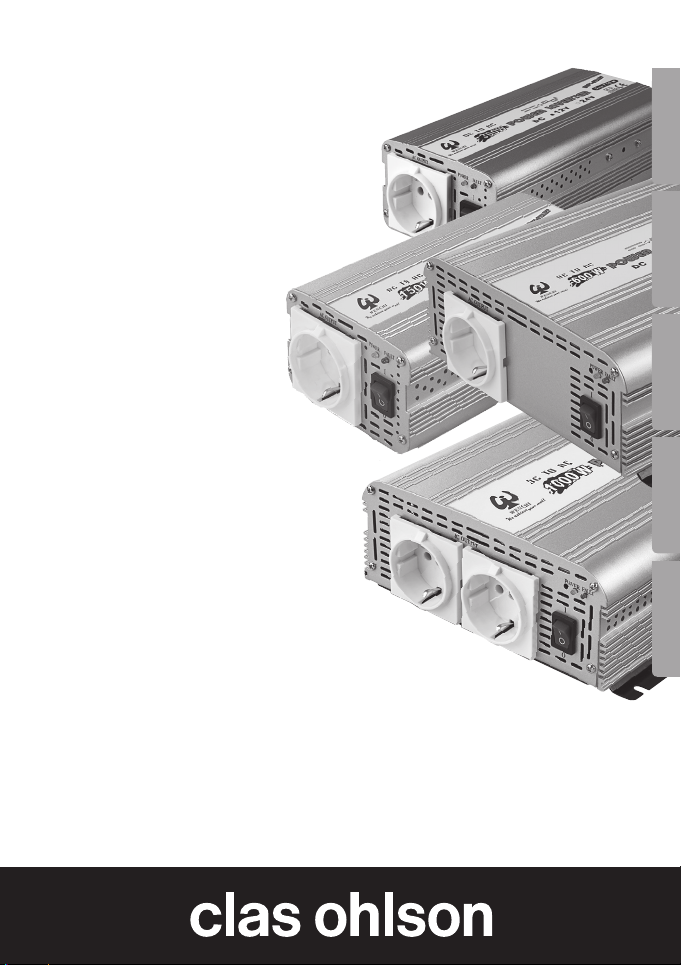
Inverter
Växelriktare
Vekselretter
Invertteri
Wechselrichter
Art.no. Model
18-2052 WHS-150-UK
32-8559 WHS-150
18-2053 WHS-300-UK
32-8560 WHS-300
18-2054 WHS-600-UK
32-8561 WHS-600
18-2055 WHS-1000-UK
32-8562 WHS-1000
18-2056 WHS-300-UK
32-8565 WHS-300
18-2057 WHS-1000-UK
32-8567 WHS-1000
EnglishSvenskaNorskSuomiDeutsch
Ver. 20180914
Page 2

2
Page 3

Inverter
Art.no Model Art.no Model
18-2052 WHS-150-UK 32-8559 WHS-150
18-2053 WHS-300-UK 32-8560 WHS-300
18-2054 WHS-600-UK 32-8561 WHS-600
18-2055 WHS-1000-UK 32-8562 WHS-1000
18-2056 WHS-300-UK 32-8565 WHS-300
18-2057 WHS-1000-UK 32-8567 WHS-1000
Please read theentire instruction manual before using and save it for future
use. We apologise for any text or photo errors and any changes of technical
data. If you have any questions concerning technical problems please
contact our Customer Service Department (see address on reverse.)
Introduction
• Short-circuit protection, theinverter switches off until theshort-circuit
has ceased.
• Warning and protection against low insufficient input voltage:
The inverter warns you if theinput voltage is too low. A warning buzzer
sounds when theinput voltage drops to 10.5 V (± 0.5 V) (for 12 V model)
and 21 V (± 1 V) (for 24 V model).
If thevoltage drops too low, theinverter will automatically shut itself off to
protect itself and thebattery. The red diode lights and theinverter shuts
off automatically at 10 V (± 0,5 V) (for 12 V model) and at 20 V (± 1 V)
(for 24 V model).
• Surge Protector: The red diode lights and theinverter shuts off automatically at 15.5 V (± 1 V) (for 12 V model) and at 30 V (± 1.5 V)
(for 24 V model).
• Overload Protection: The red diode warning lamp lights and theinverter
automatically shuts off in case of constant overload or high peak loads.
• Thermal Protection: The red diode lights and theinverter shuts off
automatically at temperatures higher than 60 °C (± 5 °C).
English
3
Page 4

Warning
• Make sure that the socket that the product is plugged into is easily
accessible so that you can quickly disconnect it and the product from
English
the mains when needed.
• Do not connect products of this type to each other.
• Do not cover the product.
• The inverter should not be exposed to rain or moisture
• Never open theinverter yourself, repairs should be carried out by
qualified personal using original spare parts, otherwise theproduct could
become dangerous to use.
• Always disconnect thebattery terminals before servicing or carrying out
any adjustments to connected load appliances!
• Be very careful when handling lead-acid batteries, avoid sparking at
the terminals.
• Keep theinverter out of children’s reach; remember that thevoltage from
it is as dangerous as that from aregular wall socket!
• If themains lead or other cables on theinverter are damaged they have
to be replaced. Use only original replacement parts from thesupplier.
• The product may only be used in vehicles.
• Make sure that you connect thecorrect lead to thecorrect terminal.
Reversed connection can damage theinverter, which is not covered
by theguarantee.
• The connection leads between theinverter and thebattery should be
kept short, max. 2 m.
• Never use longer leads than needed between theinverter and theload
appliance, thelonger thelead thehigher thevoltage drop.
• Do not load theinverter when connecting or disconnecting it.
4
Page 5
Connection
The 150 W and 300 W models come with acigarette lighter plug and
connection lead.
Check that thecigarette lighter socket has 12V/24 V output voltage and that
thecigarette lighter socket has plus (+) in thecentre before theinverter is
connected. The 300 W, 600 W and 1000 W models come with battery
connection clips and leads.
1. Connect thered lead to thered (+) terminal on theinverter and the
(+) battery terminal.
2. Connect theblack lead to theblack (-) terminal on theinverter and the
(-) battery terminal.
3. Make sure that theconnections are tight to avoid sparking and voltage
drop.
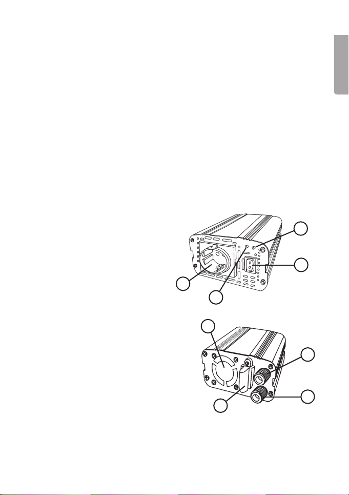
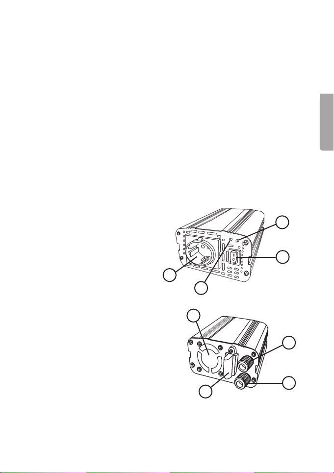
Front
1. [ FAULT ] Red LED
2. Switch [ ON/STANDBY ]
3. [ POWER ] Green LED
4. 230 V wall socket
4
3
1
English
2
Back
5. [ + ] Red. (+) terminal (positive)
(Not on the150 W model)
6. [ - ] Black. (+) terminal (negative)
(Not on the150 W model)
7. Fuse (only on the150 W and
300 W models)
8. Cooling Fan (Not on the150 W
model)
8
5
6
7
5
Page 6

Use
• Make sure that thebattery to be used as apower source is fully charged.
• Make sure that theload appliance has alower power consumption that
English
theinverter’s max. power output.
• Do not connect any sensitive appliances which need sine wave AC voltage
(the inverter produces amodified square waveform).
1. Place theinverter on alevel surface, protected from rain and moisture
and with good air circulation so theinverter does not overheat. Do place
theinverter in direct sunlight or near aheat source.
2. Make sure that theload is switched off, and then plug theload appliance
into theinverter.
3. Turn theinverter on (turn thepower switch to 1), always turn theinverter
on before turning on theload!
4. The green LED (3) illuminates when theinverter is working normally
5. If theinverter’s warning buzzer sounds when you turn it on, theinput
voltage is too low and theinverter will shut off automatically.
Recharge thebattery!
Note:
• Disconnect theinverter from thebattery before starting thevehicle or
before recharging thebattery.
• Disconnect theinverter when it is not in use.
• Discharged batteries are sensitive to frost, recharge batteries before
storing them.
6
Page 7
Powering acirculation pump etc. with aninverter
It is possible to run acirculation pump using aninverter as long as
theinverter’s power is matched to thecirculation pump’s needs. A circulation
pump requires agreat deal of initial power ( it uses more power when starting,
up to 3 times as much as when in normal operation). In order to do this,
aninverter with twice or even three times thepower is needed.
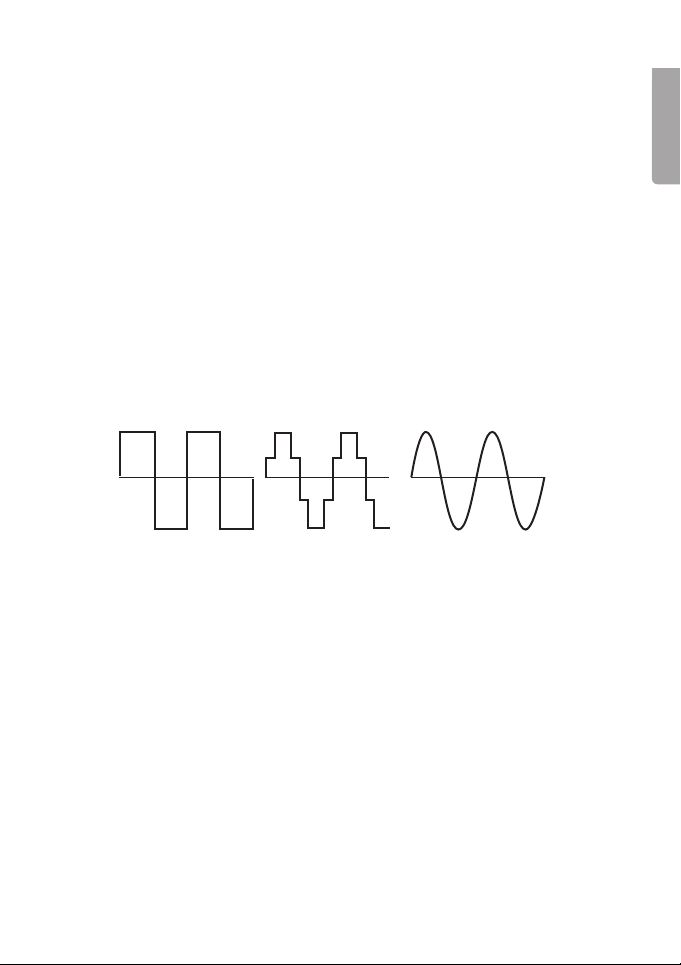
The reason why inverters with asine wave output are often used for running
circulation pumps is that apump running on asquare wave output (and even
modified “stepped” sine waves) can make anoise. The noise is caused by
thesudden phase shifts in asquare wave* (or modified sine wave), creating aresonance in thewindings of thepump which can be transferred to
thecopper conductors and other components connected to thepump.
If you have no choice, you can use aninverter producing asquare wave
output (or modified sine wave), but aninverter producing asine wave is preferable for quieter running.
* The difference between square wave, modified sine wave and sine wave:
Measuring AC voltage
This inverter produces “modified square wave” AC voltage, this means that
thevoltage measurement must use avoltmeter that measures “TRUE RMS”
if themeasurement is to be accurate. If another type of voltmeter is used
thevoltage shown might be 20–30 V lower than theactual voltage.
English
7
Page 8
Troubleshooting
1. Switch off theinverter straight away if there is aproblem.
2. Disconnect theload appliance.
English
3. Inspect theload appliance and all connections.
Low or no output voltage
• The inverter has abad connection to thebattery, check all
theconnections.
• Check that thefuse has not blown (only applies to 150 W and 300 W
models). On the600 W and 1000 W models thefuse is mounted on
thecircuit board and must only be replaced by qualified electricians.
• Measuring with thewrong instrument, see Measuring AC voltage.
The red LED (1) illuminates
• The battery is too low, recharge thebattery.
• The inverter is overloaded, reduce theload.
• The inverter has become too warm. Move it to acooler place, check that
theair vents are not blocked. There should be at least 50 cm around
theinverter to ensure cooling.
• The inverter is defective, ring our customer service department.
Responsible disposal
This symbol indicates that this product should not be disposed
of with general household waste. This applies throughout
theentire EU. In order to prevent any harm to theenvironment
or health hazards caused by incorrect waste disposal,
theproduct must be handed in for recycling so that thematerial
can be disposed of in aresponsible manner. When recycling
your product, take it to your local collection facility or contact
theplace of purchase. They will ensure that theproduct is
disposed of in anenvironmentally sound manner.
8
Page 9
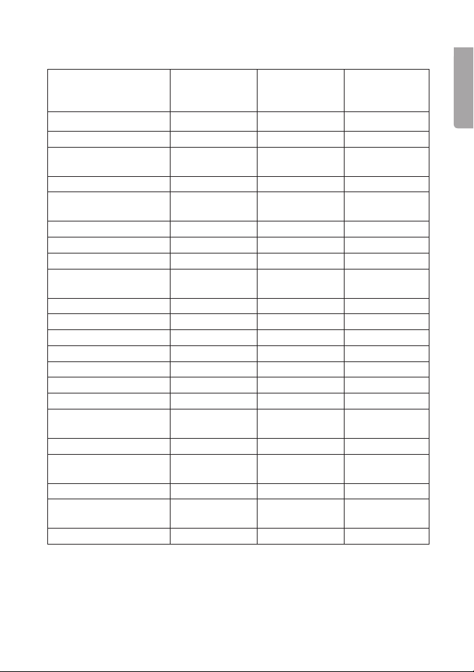
Technical Specification
Article number
Model
Power 12 V DC 12 V DC 24 V DC
Constant power output 150 W 300 W 300 W
Intermittent power
output
Voltage deviation ± 10 % ± 10 % ± 10 %
Output voltage Modified sine
Power 12–14 V DC 12–14 V DC 20–30 V DC
Efficiency > 85 % > 85 % > 85 %
Idling consumption < 0.3 A < 0.5 A < 0.3 A
Thermal protection,
auto-shut off
Cooling fan No Yes Yes
Short circuit protection Yes Yes Ye s
Soft start Yes Yes Yes
Overvoltage protection Ye s Yes Yes
Automatic shut off at: 15 V (± 1.0 V) 15 V (± 1.0 V) 30 V (± 1.5 V)
Low power alarm 10.5 V (± 0.5 V) 10.5 V (± 0.5 V) 21.0 V (± 1 V)
Automatic shut off at: 10.0 V (± 0.5 V) 10.0 V (± 0.5 V) 20.0 V (± 1 V)
Protection against
wrong polarity (fuse)
Input fuse 20 A 35 A 20 A
Operating
temperature
Size (mm) 192×96×65 218×96×65 218×96×65
Weight
(net, without leads)
Hi-Pot Yes Yes Ye s
18-2052/
32-8559
WHS-150 12V
375 W 750 W 750 W
wave
60 °C (± 10 °C) 60 °C (± 10 °C) 60 ºC (± 10 °C)
Yes Yes Yes
-15 till 50 °C -15 till 50 °C -15 till 50 °C
835 g 1010 g 1010 g
18-2053/
32-8560
WHS-300 12V
Modified sine
wave
18-2056/
32-8565
WHS-300 24V
Modified sine
wave
English
9
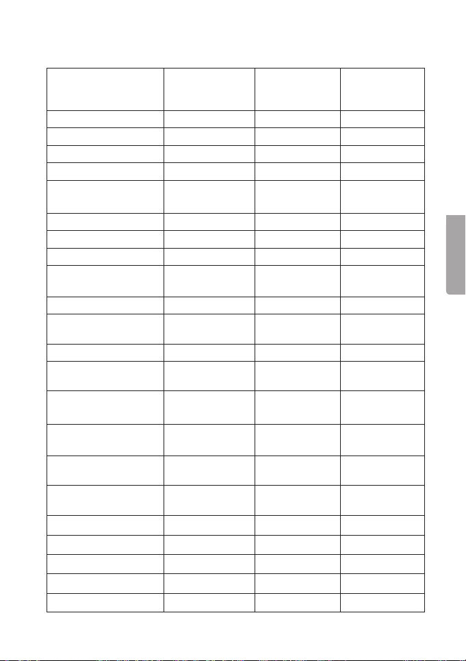
Page 10

Article number
Model
Power 12 V DC 12 V DC 24 V DC
English
Constant power
18-2054/
32-8561
WHS-600 12 V
18-2055/
32-8562
WHS-1000 12 V
600 W 1000 W 1000 W
output
Intermittent power
1500 W 2500 W 2500 W
output
Voltage deviation ± 10 % ± 10 % ± 10 %
Output voltage Modified sine
wave
Modified sine
wave
Power 12 V DC 12 V DC 20–30 V DC
Efficiency > 85 % > 85 % > 85 %
Idling consumption < 0,65 A < 1,0 A < 0,9 A
Thermal protection,
60 °C (± 10 ºC) 60 °C (± 10 ºC) 60 °C (± 10 °C)
auto-shut off
Cooling fan Yes Yes Yes
Kortslutningsskydd Yes Ye s Yes
Soft start Yes Yes Ye s
Overvoltage
Yes Yes Ye s
protection
Automatic shut off at 15 V (± 1,0 V) 15 V (± 1,0 V) 30 V (± 1,5 V)
Low power alarm 10,5 V (± 0,5 V) 10,5 V (± 0,5 V) 21 V (± 1,0 V)
Automatic shut off at 10,0 V (± 0,5 V) 10,0 V (± 0,5 V) 20 V (± 1,0 V)
Protection against
Yes Yes Ye s
wrong polarity (fuse)
Input fuse 20 A (4 st) 35 A (4 st) 35 A (2 st)
Operating temperature -15 to 50 °C -15 to 50 °C -15 to 50 °C
Size (mm) 208×205×76 300×205×78 300×205×78
Weight (net, without
2100 g 3250 g 3250 g
leads)
Hi-Pot Yes Ye s Ye s
18-2057/
32-8567
WHS-1000 24 V
Modified sine
wave
10
Page 11

Växelriktare
Art.nr Modell Art.nr Modell
18-2052 WHS-150-UK 32-8559 WHS-150
18-2053 WHS-300-UK 32-8560 WHS-300
18-2054 WHS-600-UK 32-8561 WHS-600
18-2055 WHS-1000-UK 32-8562 WHS-1000
18-2056 WHS-300-UK 32-8565 WHS-300
18-2057 WHS-1000-UK 32-8567 WHS-1000
Läs igenom hela bruksanvisningen före användning och spara den sedan
för framtida bruk. Vi reserverar oss för ev. text- och bildfel samt ändringar av
tekniska data. Vid tekniska problem eller andra frågor, kontakta vår kundtjänst
(se adressuppgifter på baksidan).
Introduktion av växelriktarens skydd
• Kortslutningsskydd, växelriktaren stängs av till kortslutningen har upphört.
• Varning och skydd vid låg inspänning:
Växelriktaren varnar om inspänningen blir för låg. En varningssummer ljuder
när ingångsspänningen har sjunkit till 10,5 V (± 0,5 V) (för 12 V modell) och
21 V (± 1 V) (för 24 V modell).
Om spänningen sjunker för lågt kommer växelriktaren att stängas av
automatiskt för att skydda sig själv och batteriet. Den röda dioden
tänds och växelriktaren stängs av automatiskt vid 10 V (±0,5 V) (för 12 V
modell) och vid 20 V (± 1,0 V) (för 24 V modell).
• Överspänningsskydd: Den röda dioden tänds och växelriktaren stängs av
automatiskt vid 15,5 V (± 1 V) (för 12 V modell) och vid 30 V (± 1,5 V)
(för 24 V modell).
• Överbelastningsskydd: Den röda dioden tänds och växelriktaren stängs
av automatiskt vid kontinuerlig överbelastning eller vid hög toppbelastning
• Termiskt skydd: Den röda dioden tänds och växelriktaren stängs av
automatiskt vid temperatur högre än 60 ºC (± 5 ºC).
Svenska
11
Page 12

Varning
• Se till att uttaget där produkten placeras är lättåtkomligt så att den och
ansluten produkt vid behov snabbt kan frånkopplas från elnätet.
• Anslut inte produkter av denna typ med varandra.
• Täck inte över produkten.
• Växelriktaren skall skyddas mot regn och fukt.
• Öppna aldrig växelriktaren själv, reparationer av produkten ska alltid
utföras av fackman, med originalreservdelar, annars finns det risk för att
Svenska
produkten kan vålla olyckor eller personskada.
• Ta alltid bort anslutningarna till batteriet innan service och justering av
ansluten enhet!
• Var mycket försiktig vid användning av blybatterier, undvik gnistbildning
vid anslutning.
• Placera växelriktaren utom räckhåll för barn, tänk på att spänningen från
den är lika farlig som dina vanliga el-uttag!
• Om nätsladden eller andra kablar är skadade ska de bytas ut.
Använd endast originalreservdelar från leverantören.
• Produkten får endast användas i fordon.
• Anslutningskablarna mellan batteri och växelriktare skall hållas korta,
max 2 meter.
• Använd aldrig längre kablar än vad som behövs mellan växelriktare och
strömförbrukare, lång kabel leder till spänningsfall.
• Kontrollera att du kopplar rätt kabel till rätt pol. Omvänd inkoppling kan
orsaka skador på växelriktaren som inte omfattas av garantin.
• Belasta ej växelriktaren när du ansluter eller tar bort anslutningar.
12
Page 13
Anslutning
För 150 W och 300 W modellerna medföljer kabel med propp för
cigarettändaruttag.
Kontrollera att cigarettändaruttaget har 12V/24 V utspänning och att cigaretttändaruttaget har plus (+) i centrum innan växelriktaren ansluts.
För 300 W, 600 W och 1000 W modellerna medföljer kablar med batteriklämmor för anslutning till polerna på ett batteri.
1. Anslut röd kabel till den röda (+) terminalen på växelriktaren och till
(+) polen på batteriet.
2. Anslut svart kabel till svarta (-) terminalen på växelriktaren och till
(-) polen på batteriet.
3. Kontrollera att anslutningarna sitter fast ordentligt, för att förebygga
gnistbildning och spänningsfall.
Framsidan
1. [ FAULT ] Röd lysdiod
2. Strömbrytare [ ON/STANDBY ]
3. [ POWER ] Grön lysdiod
4. 230 V-uttag
Baksidan
5. [ + ] Röd. (+) terminal (positiv)
(Finns ej på 150 W modellen)
6. [ - ] Svart. (-) terminal (negativ)
(Finns ej på 150 W modellen)
7. Säkring (endast 150 W och
300 W -modellerna)
8. Kylfläkt (Finns ej på 150 W
modellen)
4
3
8
7
1
2
Svenska
5
6
13
Page 14

Användning
• Se till att batteriet som ska användas som strömkälla är fulladdat.
• Kontrollera att de anslutna enheterna har en lägre strömförbrukning än
växelriktarens max. uteffekt.
• Anslut inga känsliga elektriska produkter som behöver växelspänning i
form av sinusvåg (växelriktaren lämnar modifierad fyrkantvåg.)
1. Placera växelriktaren på en plan yta, väl skyddad från regn, fukt och
Svenska
med god luftväxling så kylningen av växelriktaren inte hindras, inte heller
i direkt solljus eller nära någon värmekälla.
2. Kontrollera att strömförbrukaren är avslagen, anslut sedan
strömförbrukarens stickpropp till uttaget på växelriktaren.
3. Slå på växelriktaren (ställ strömbrytaren på 1), slå alltid på växelriktaren
innan den anslutna strömförbrukaren startas!
4. Den gröna lysdioden (3) lyser när växelriktaren fungerar normalt.
5. Om växelriktarens varningssummer piper vid start indikerar det att
ingångsspänningen är för låg och sedan stängs växelriktaren av
automatiskt. Ladda upp batteriet!
Tänk på detta!
• Koppla ifrån växelriktaren från batteriet innan fordonet startas eller innan
batteriet ska laddas upp.
• Koppla ifrån växelriktaren när den inte används.
• Urladdade batterier är känsliga för frost, ladda upp batterier innan förvaring.
14
Page 15

Driva cirkulationspump etc. med växelriktare
Det går att köra en cirkulationspump på en växelriktare under förutsättning att
växelriktarens effekt är proportionerad mot cirkulationspumpen. En cirkulationspump har väldigt hög startström (den drar mer ström vid start än angiven
ström, upp till 3 ggr så mycket som vid normal drift), för att det ska fungera
krävs därför en dubbelt (ibland tre gånger) så kraftig växelriktare.
Anledningen till att man ofta använder en växelriktare med s.k. sinusvåg till
cirkulationspumpar är att det vid användande av fyrkantsvåg (och även modifierad ”trappstegsformad” sinusvåg) kan bli ett visst oljud. Oljudet uppstår
p.g.a. de snabba fasvändningarna som blir av fyrkantsvågen* (eller modifierad
sinusvåg), detta skapar ett resonansljud i pumpens lindningar som sedan kan
sprida sig via kopparledningar och dyl. som är anslutet till pumpen.
Vid ”nöddrift” kan man kanske nöja sig med en växelriktare som lämnar fyrkantsvåg (eller modiferad sinusvåg), men en växelriktare som lämnar sinusvåg
är att föredra just för att få en tystare drift.
Skillnad fyrkantsvåg, modifierad ”trappstegsformad” sinusvåg och sinusvåg:
Mätning av växelspänning
Växelriktaren lämnar växelspänning i form av modifierad fyrkantvåg, det medför att spänningsmätning måste ske med en voltmätare som mäter ”TRUE
RMS” för att mätningen ska vara rättvisande, med annan typ av voltmätare
kommer spänningen att visas 20–30 V lägre än den verkliga spänningen.
Svenska
15
Page 16

Felsökning
1. Stäng av växelriktaren omedelbart vid problem.
2. Koppla ifrån anslutna strömförbrukare.
3. Kontrollera anslutna strömförbrukare och alla anslutningar.
Låg utspänning eller ingen utspänning
• Växelriktaren har dålig kontakt med batteriet, kontrollera anslutningarna.
• Montrollera att säkringen är hel (gäller endast 150 W och 300 W
Svenska
modellerna). På 600 W och 1000 W–modellerna sitter säkringarna
monterade på kretskortet och får endast bytas av kvalificerad
servicepersonal.
• Mätning med fel instrument, se Mätning av växelspänning.
Den röda lysdioden (1) lyser
• Batteriet har för låg spänning, ladda batteriet.
• Växelriktaren överbelastas, minska belastningen.
• Växelriktaren har blivit för het. Ställ växelriktaren på en svalare plats,
kontrollera att inte ventilationsöppningarna är blockerade. Det bör vara
minst 50 cm fritt runt växelriktaren för att garantera kylningen.
• Växelriktaren är defekt, ring vår kundtjänst.
Avfallshantering
Denna symbol innebär att produkten inte får kastas
tillsammans med annat hushållsavfall. Detta gäller inom
hela EU. För att förebygga eventuell skada på miljö och
hälsa, orsakad av felaktig avfallshantering, ska produkten
lämnas till återvinning så att materialet kan tas omhand på
ettansvarsfullt sätt. När du lämnar produkten till återvinning,
använd dig av de returhanteringssystem som finns där du
befinner dig eller kontakta inköpsstället. De kan se till att
produkten tas om hand på ettför miljön tillfredställande sätt.
16
Page 17

Specifikationer
Artikelnummer
Modell
Drivspänning 12 V DC 12 V DC 24 V DC
Kontinuerlig uteffekt 150 W 300 W 300 W
Intermittent uteffekt 375 W 750 W 750 W
Spänningsvariation ± 10 % ± 10 % ± 10 %
Utspänning, typ Modifierad
Drivspänning 12–14 V DC 12–14 V DC 20–30 V DC
Verkningsgrad > 85 % > 85 % > 85 %
Tomgångsförbrukning < 0,3 A < 0,5 A < 0,3 A
Termiskt skydd, auto-
matisk avstängning
Kylfläkt Nej Ja Ja
Kortslutningsskydd Ja Ja Ja
Mjuk start Ja Ja Ja
Överspänningsskydd Ja Ja Ja
Automatisk
avstängning vid:
Alarm för låg
drivspänning
Automatisk
avstängning vid:
Skydd mot fel polaritet
(säkring)
Ingångssäkring 20 A 35 A 20 A
Användnings-
temperatur
Storlek (mm) 192×96×65 218×96×65 218×96×65
Vikt (netto, utan kablar) 835 g 1010 g 1010 g
Hi-Pot Ja Ja Ja
18-2052/
32-8559
WHS-150 12 V
sinusvåg
60 °C (± 10 °C) 60 °C (± 10 °C) 60 °C (± 10 °C)
15 V (± 1,0 V) 15 V (± 1,0 V) 30 V (± 1,5 V)
10,5 V (± 0,5 V) 10,5 V (± 0,5 V) 21,0 V (± 1 V)
10,0 V (± 0,5 V) 10,0 V (± 0,5 V) 20,0 V (± 1 V)
Ja Ja Ja
-15 till 50 °C -15 till 50 °C -15 till 50 °C
18-2053/
32-8560
WHS-300 12 V
Modifierad
sinusvåg
18-2056/
32-8565
WHS-300 24 V
Modifierad
sinusvåg
Svenska
17
Page 18

Artikelnummer
Modell
18-2054/
32-8561
WHS-600 12 V
18-2055/
32-8562
WHS-1000 12 V
Drivspänning 12 V DC 12 V DC 24 V DC
Kontinuerlig
600 W 1000 W 1000 W
uteffekt
Intermittent uteffekt 1500 W 2500 W 2500 W
Spänningsvariation ± 10 % ± 10 % ± 10 %
Utspänning, typ Modifierad
Svenska
Drivspänning 12 V DC 12 V DC 20–30 V DC
sinusvåg
Modifierad
sinusvåg
Verkningsgrad > 85 % > 85 % > 85 %
Tomgångsförbrukning < 0,65 A < 1, < 0,9 A
Termiskt skydd, auto-
60 °C (± 10 °C) 60 °C (± 10 °C) 60 °C (± 10 °C)
matisk avstängning
Kylfläkt Ja Ja Ja
Kortslutningsskydd Ja Ja Ja
Mjuk start Ja Ja Ja
Överspänningsskydd Ja Ja Ja
Automatisk
15 V (± 1,0 V) 15 V (± 1,0 V) 30 V (± 1,5 V)
avstängning vid
Alarm för låg
10,5 V (± 0,5 V) 10,5 V (± 0,5 V) 21 V (± 1,0 V)
drivspänning
Automatisk
10,0 V (± 0,5 V) 10,0 V (± 0,5 V) 20 V (± 1,0 V)
avstängning vid
Skydd mot fel
Ja Ja Ja
polaritet (säkring)
Ingångssäkring 20 A (4 st) 35 A (4 st) 35 A (2 st)
Användnings-
-15 till 50 °C -15 till 50 °C -15 till 50 °C
temperatur
Storlek (mm) 208×205×76 300×205×78 300×205×78
Vikt (netto,
2100 g 3250 g 3250 g
utan kablar)
Hi-Pot Ja Ja Ja
18-2057/
32-8567
WHS-1000 24 V
Modifierad
sinusvåg
18
Page 19

Vekselretter
Art.nr. Modell Art.nr. Modell
18-2052 WHS-150-UK 32-8559 WHS-150
18-2053 WHS-300-UK 32-8560 WHS-300
18-2054 WHS-600-UK 32-8561 WHS-600
18-2055 WHS-1000-UK 32-8562 WHS-1000
18-2056 WHS-300-UK 32-8565 WHS-300
18-2057 WHS-1000-UK 32-8567 WHS-1000
Les nøye igjennom hele bruksanvisningen og ta vare på den til senere bruk.
Vi reserverer oss mot ev. tekst- og bildefeil, samt forandringer av tekniske
data. Ved tekniske problemer eller andre spørsmål, ta kontakt med vårt
kundesenter (se opplysninger på baksiden).
Introduksjon av vekselretterens beskyttelse
• Kortslutningsbeskyttelse, vekselretteren stenges til kortslutningen har opphørt.
• Varsling og beskyttelse ved lang innspenning:
Vekselretteren varsler hvis innspenningen blir for lang. En varselsummer
låter når inngagnsspenningen har sunket til 10,5 V (± 0,5 V) (for 12 V
modellen) og 21 V (± 1 V) (for 24 V modellen).
Hvis spenningen synker for mye kommer vekselretteren til å stenges
automatisk for å beskytte seg selv og batteriet. Den røde dioden tennes
og vekselretteren skrus av automatisk10 V (± 0,5 V) (for 12 V modellen)
og ved 20 V (± 1,0 V) (for 24 V modellen).
• Overspenningsbeskyttelse: Den røde dioden tennes og vekselretteren
skrus av automatisk15,5 V (± 1 V) (for 12 V modellen) og ved 30 V (± 1,5 V)
(for 24 V modellen).
• Overbelastningsbeskyttelse: Den røde dioden tennes og vekselretteren
stenges av automatisk ved kontinuerlig overbelastning eller ved høy
toppbelastning.
• Termisk beskyttelse: Den røde dioden tennes og vekselretteren stenges
automatisk ved temperatur høyere enn 60 °C (± 5 °C).
Norsk
19
Page 20

Advarsel
• Sørg for at strømuttaket der produktet plasseres er lett tilgjengelig,
slik at det tilkoblede produktet raskt kan kobles fra strømnettet.
• Koble ikke produkter av denne typen sammen.
• Produktet må ikke tildekkes.
• Vekselretteren må beskyttes mot regn og fuktighet.
• Åpne ikke vekselretterens deksel. Alle reparasjoner av produktet skal
utføres av fagpersoner og med originaldeler. Dersom ikke dette følges er
det fare for at produktet kan volde ulykker eller personskader.
• Koble alltid vekselretteren fra batteriet før service og justering av
tilkoblet enhet!
• Vær varsom ved bruk av blybatterier. Unngå gnister ved tilkobling.
• Vekselretteren må plasseres utenfor barns rekkevidde. Husk at
Norsk
spenningen fra den er like farlig som fra de vanlige strømuttakene!
• Skift ut skadede ledninger. Bruk kun originale reservedeler.
• Produktet må kun brukes i kjøretøy.
• Tilkoblingskablene mellom batteri og vekselretter skal holdes korte,
maks. 2 meter.
• Bruk aldri lengre kabler enn det som trengs mellom vekselretteren og
strømforbrukeren. Lang kabel fører til spenningsfall.
• Kontroller at du kobler riktig kabler til polene. Omvendt tilkobling kan
forårsake skader på vekselretteren. Dette dekkes ikke av garantien.
• Belast ikke vekselretteren når du kobler til eller fra tilkoblinger.
20
Page 21

Tilkobling
For 150 W og 300 W modellene følger det med kabel med kontakt for
sigarettenneruttak.
Kontroller at sigarettenneruttaket har 12 V / 24 V utspenning og at
sigarettenneruttaket har pluss (+) i sentrum, før vekselretteren kobles til.
For 300 W, 600 W og 1000 W modellene følger det med kabler med
batteriklemmer for tilkobling til polene på ett batteri.
1. Koble den røde kabelen til den røde (+) terminalen på vekselretteren og til
(+)-polen på batteriet.
2. Koble den sorte kabelen til den sorte (-) terminalen på vekselretteren og
til (-)-polen på batteriet.
3. Kontroller at tilkoblingene sitter godt fast, for å forebygge gnistdannelse
og spenningsfall.
Forsiden
1. [ FAULT ] Rød lysdiode
2. Strømbryter [ ON/STANDBY ]
3. [ POWER ] Grønn lysdiode
4. 230 V-uttak
Baksiden
5. [ + ] Rød (+) terminal (positiv)
(Finnes ikke på 150 W modellen)
6. [ - ] Sort (-) terminal (negativ)
(Finnes ikke på 150 W modellen)
7. Sikring (kun på 150 W og
300 W -modellene)
8. Kjølevifte (Finnes ikke på
150 W modellen)
Norsk
1
2
4
3
8
5
6
7
21
Page 22

Bruk
• Påse at batteriet som skal brukes som strømkilde er fulladet.
• Kontroller at de tilkoblede enhetene har et lavere strømforbruk enn
vekselretterens maksimums uteffekt.
• Ikke koble til følsomme elektriske produkter som trenger vekselstrøm
i form av sinusbølge (vekselretteren avgir modifiserte firkantbølger).
1. Plasser vekselretteren på en plan flate. Ikke utsett den for regn eller
fuktighet. Sørg for god luftventilering slik at den blir godt avkjølt.
Vekselretteren skal heller ikke plasseres i direkte sollys eller for nærme
varmekilder.
2. Kontroller at strømforbrukeren er skrudd av. Koble strømforbrukerens
støpsel i vekselretterens uttak.
3. Skru på vekselretteren (still strømbryteren på 1). Slå alltid på
Norsk
vekselretteren før den tilkoblede strømforbrukeren startes.
4. Den grønne lysdioden (3) lyser når vekselretteren fungerer normalt.
5. Dersom vekselretterens varselsummer piper ved start, indikerer det at
inngangsspenningen er for lav og deretter stenges vekselretteren av
automatisk. Lad opp batteriet!
Husk følgende:
• Koble vekselretteren fra batteriet før batteriet lades opp.
• Koble fra vekselretteren når den ikke er i bruk.
• Utladede batterier er følsomme for frost. Lad opp batterier før du legger
dem til lagring.
22
Page 23

Å drive sirkulasjonspumpe etc. med vekselsretter
Det er fullt mulig å kjøre en sirkulasjonspumpe på en vekselretter under forutsetning av at vekselretterens effekt er proporsjonert mot sirkulasjonspumpen.
En sirkulasjonspumpe har veldig høy startstrøm (den drar mer strøm i starten
enn angitt strømforbruk, inntil hele 3 ganger så mye som ved normal drift), for
at det skal fungere kreves derfor en dobbelt (av og til 3 ganger) så kraftig
vekselretter.
Grunnen til at man ofte bruker en vekselretter med f.eks. sinuskurver til
sirkulasjonspumper er at det ved bruk av firkantbølger (og også modifiserte
”trappetrinnformede” bølger) kan bli en viss ulyd. Ulyden oppstår p.g.a. de
raske fasevenningene som firkantbølgene* (eller modifiserte bølger) lager.
Dette skaper en resonanslyd i pumpen som deretter kan spre seg via
kobberledningene som er koblet til pumpen.
Ved ”nøddrift” kan man kanskje klare seg med en vekselretter som gir firkantbølger, men en vekselretter som gir sinuskurvede bølger er å foretrekke for å
få en stillere drift.
Nedenfor vises grafisk firkantbølger, modifiserte ”trappetrinnsformede”
sinusbølger og sinusbølger:
Norsk
Måling av vekselspenning
Vekselretteren gir vekselspenning i form av modifiserte firkantbølger. Det medfører at spenningsmåling må skje med et voltmeter som måler ”TRUE RMS” for
at målingen skal være riktig. Med andre voltmetre vil spenningen vises 20–30 V
lavere enn den virkelige spenningen.
23
Page 24

Feilsøking
1. Ved problemer må vekselretteren skrus av umiddelbart.
2. Koble fra alle tilkoblede strømforbrukere.
3. Kontroller de tilkoblede strømforbrukerne og alle koblinger.
Lav spenning ut eller ingen spenning ut i det hele tatt
• Vekselretteren har dårlig kontakt med batteriet. Kontroller koblingene.
• Kontroller at sikringen er hel (gjeller kun for 15 W og 300 W modellene).
På 600 W og 1000 W–modellene sitter sikringene montert på kretskortet
og må kun skiftes av kvalifiserte fagpersoner.
• Måling med feil instrument, se Måling av vekselspenning.
Den røde lysdioden (1) lyser
Norsk
• Batteriet har for lav spenning. Lad batteriet.
• Vekselretteren overbelastes. Reduser belastningen.
• Vekselretteren har blitt for varm. Still den på et kjørlig sted, kontroller at
ikke ventilasjonsåpningene er blokkert. Det bør være minst 50 cm fritt
rom rundt vekselretteren for å garantere avkjøling.
• Vekselretteren er defekt. Ring vår kundeservice.
Avfallshåndtering
Symbolet viser til at produktet ikke skal kastes sammen med
husholdningsavfallet. Dette gjelder ihele EØS-området. For
åforebygge eventuelle skader på helse og miljø, som følge av
feil håndtering av avfall, skal produktet leveres til gjenvinning,
slik at materialet blir tatt hånd om på enansvarsfull måte.
Benytt miljøstasjonene som er der du befinner deg eller
ta kontakt med forhandler. De kan se til at produktet blir
behandlet på entilfredsstillende måte som gagner miljøet.
24
Page 25
Teknisk spesifikasjon
Artikkelnummer
Modell
Spenning 12 V DC 12 V DC 24 V DC
Kontinuerlig uteffekt 150 W 300 W 300 W
Ujevn uteffekt 375 W 750 W 750 W
Spenningsvariasjon ± 10 % ± 10 % ± 10 %
Spenning ut, type Modifiserte
Spenning 12–14 V DC 12–14 V DC 20–30 V DC
Virkningsgrad > 85 % > 85 % > 85 %
Tomgangsforbruk < 0,3 A < 0,5 A < 0,9 A
Termisk beskyttelse,
automatisk avstengning
Kjølevifte Nei Ja Ja
Beskyttelse ved
kortslutning
Myk start Ja Ja Ja
Overspennings-
beskyttelse
Automatisk
avstengning ved
Alarm for lav
spenning
Automatisk
avstengning ved
Beskyttelse mot feil
polaritet (sikring)
Inngangssikring 20 A 35 A 20 A
Brukstemperatur -15 til +50 °C -15 til +50 °C -15 til +50 °C
Størrelse (mm) 192×96×65 218×96×65 218×96×65
Vekt (netto, uten kabler) 835 g 1 010 g 1 010 g
Hi-Pot Ja Ja Ja
18-2052/
32-8559
WHS-150 12 V
sinusbølger
60 ºC (± 10 ºC) 60 ºC (± 10 ºC) 60 ºC (± 10 ºC)
Ja Ja Ja
Ja Ja Ja
15 V (± 1,0 V) 15 V (± 1,0 V) 30 V (± 1,5 V)
10,5 V (± 0,5 V) 10,5 V (± 0,5 V) 21,0 V (± 1 V)
10,0 V (± 0,5 V) 10,0 V (± 0,5 V) 20,0 V (± 1 V)
Ja Ja Ja
18-2053/
32-8560
WHS-300 12 V
Modifiserte
sinusbølger
18-2056/
32-8565
WHS-300 24 V
Modifiserte
sinusbølger
Norsk
25
Page 26

Artikkelnummer
Modell
18-2054/
32-8561
WHS-600 12 V
18-2055/
32-8562
WHS-1000 12 V
Spenning 12 V DC 12 V DC 24 V DC
Kontinuerlig uteffekt 600 W 1000 W 1000 W
Ujevn uteffekt 1500 W 2500 W 2500 W
Spenningsvariasjon ± 10 % ± 10 % ± 10 %
Spenning ut, type Modifiserte
sinusbølger
Modifiserte
sinusbølger
Spenning 12 V DC 12 V DC 20–30 V DC
Virkningsgrad > 85 % > 85 % > 85 %
Tomgangsforbruk < 0,65 A < 1,0 A < 0,5 A
Norsk
Termisk beskyttelse,
60 °C (± 10 °C) 60 °C (± 10 °C) 60 °C (± 10 °C)
automatisk avstengning
Kjølevifte Ja Ja Ja
Beskyttelse ved
Ja Ja Ja
kortslutning
Myk start Ja Ja Ja
Overspennings-
Ja Ja Ja
beskyttelse
Automatisk
15 V (± 1,0 V) 15 V (± 1,0 V) 30 V (± 1,5 V)
avstengning ved
Alarm for lav spenning 10,5 V (± 0,5 V) 10,5 V (± 0,5 V) 21 V (± 1,0 V)
Automatisk
10,0 V (± 0,5 V) 10,0 V (± 0,5 V) 20 V (± 1,0 V)
avstenging ved
Beskyttelse mot feil
Ja Ja Ja
polaritet (sikring)
18-2057/
32-8567
WHS-1000 24 V
Modifiserte
sinusbølger
Inngangssikring 20 A (4 stk.) 35 A (4 stk.) 35 A (2 stk.)
Brukstemperatur -15 til +50 °C -15 til +50 °C -15 til +50 °C
Størrelse (mm) 208×205×76 300×205×78 300×205×78
Vekt (netto, uten kabler) 2 100 g 3 250 g 3 250 g
Hi-Pot Ja Ja Ja
26
Page 27

Invertteri
Tuotenro Malli Tuotenro Malli
18-2052 WHS-150-UK 32-8559 WHS-150
18-2053 WHS-300-UK 32-8560 WHS-300
18-2054 WHS-600-UK 32-8561 WHS-600
18-2055 WHS-1000-UK 32-8562 WHS-1000
18-2056 WHS-300-UK 32-8565 WHS-300
18-2057 WHS-1000-UK 32-8567 WHS-1000
Lue käyttöohjeet ennen tuotteen käyttöönottoa. Säilytä käyttöohjeet tulevaa tarvetta varten. Pidätämme oikeuden teknisten tietojen muutoksiin. Emme vastaa
mahdollisista teksti- tai kuvavirheistä. Jos laitteeseen tulee teknisiä ongelmia,
ota yhteys myymälään tai asiakaspalveluun (yhteystiedot käyttöohjeen lopussa).
Yleistä invertterin suojista
• Oikosulkusuoja, invertteri sammuu automaattisesti oikosulun ajaksi.
• Varoitus ja suoja tulojännitteen ollessa alhainen:
Invertteri varoittaa, jos tulojännite on liian alhainen. Invertteristä kuuluu
varoitusääni kun tulojännite on laskenut 10,5 V:hen (± 0,5 V) (12 V:n malli)
ja 21 V:hen (± 1 V) (24 V:n malli).
Jos jännite laskee liian alhaiseksi, sammuu invertteri automaattisesti
suojatakseen itseään ja akkua. Punainen merkkivalo syttyy ja invertteri
sammuu automaattisesti jännitteen ollessa 10 V (± 0,5 V) (12 V:n malli)
ja 20 V (± 1,0 V) (24 V:n malli).
• Ylijännitesuoja: Punainen merkkivalo syttyy ja invertteri sammuu
automaattisesti jännitteen ollessa 15,5 V (± 1 V) (12 V:n malli) ja 30 V
(± 1,5 V) (24 V:n malli).
• Ylikuormitussuoja: Punainen merkkivalo syttyy ja invertteri sammuu
automaattisesti jatkuvan ylikuormituksen tai kuormituspiikin sattuessa.
• Lämpösuoja: Punainen merkkivalo syttyy ja invertteri sammuu
automaattisesti lämpötilan noustessa yli 60 °C:seen (± 5 °C).
Suomi
27
Page 28

Varoitus
• Varmista, että pistorasia ja siihen kiinnitetty tuote on sijoitettu helposti
saataville siten, että ne voidaan tarvittaessa kytkeä nopeasti irti sähköverkosta.
• Älä liitä tämän tyyppisiä laitteita toisiinsa.
• Älä peitä laitetta.
• Invertteri tulee suojata sateelta ja kosteudelta.
• Älä avaa invertteriä. Laitteen korjaus tulee jättää ammattilaiselle.
Korjauksessa tulee turvallisuussyistä käyttää ainoastaan alkuperäisosia,
muussa tapauksessa laitteen käyttö saattaa johtaa onnettomuuteen.
• Irrota aina liittimet akusta ennen liitetyn laitteen huoltoa ja säätöä!
• Noudata erityistä varovaisuutta työskennellessäsi lyijyakkujen kanssa,
vältä kipinän muodostumista liitännöissä.
• Sijoita invertteri lasten ulottumattomiin. Ota huomioon, että jännite on
yhtä vaarallista kuin tavallisissa sähköpistorasioissa!
• Mahdolliset vioittuneet virtajohdot ja muut johdot tulee vaihtaa.
Käytä ainoastaan valmistajan alkuperäisosia.
• Tuotetta saa käyttää ainoastaan ajoneuvoissa.
• Akun ja invertterin välisten liitoskaapeleiden tulee olla lyhyet, maks.
2 metriä.
• Älä käytä liian pitkiä kaapeleita, pitkät kaapelit johtavat jännitehäviöön.
Suomi
• Varmista, että liität oikean kaapelin oikeaan napaan. Väärä liittäminen
saattaa vioittaa invertteriä, eikä takuu kata tällaisia vahinkoja.
• Älä kuormita invertteriä kun teet liitäntöjä tai irrotat liitäntöjä.
28
Page 29

Liittäminen
150 W:n ja 300 W:n malleissa tulee mukana johto, jossa on pistoke savukkeensytytinliitäntään.
Varmista ennen invertterin liittämistä, että savukkeensytyttimen antojännite on
12 V/24 V ja että savukkeensytytinliitännässä on plus (+) keskellä.
300 W:n, 600 W:n ja 1000 W:n malleissa tulee mukana johdot ja akkupuristimet, jotka voidaan liittää akun napoihin.
1. Liitä punainen kaapeli invertterin punaiseen (+) liitäntään ja akun
plusnapaan (+).
2. Liitä musta kaapeli invertterin mustaan (-) liitäntään ja akun
miinus-napaan (-).
3. Varmista, että liitännät ovat kiinni kunnolla, muussa tapauksessa saattaa
aiheutua kipinän muodostumista ja jännitehäviötä.
Etupuoli
1. [ FAULT ] Punainen ledi
2. Virtakytkin [ ON/STANDBY ]
3. [ POWER ] Vihreä ledi
4. 230 V liitäntä
4
3
1
2
Suomi
Takaosa
5. [ + ] Punainen. (+) liitäntä
(positiivinen)
(Ei 150 W:n mallissa)
6. [ – ] Musta. (–) liitäntä (negatiivinen)
(Ei 150 W:n mallissa)
7. Sulake (ainoastaan 150 W:n ja
300 W:n malleissa)
8. Jäähdytintuuletus (Ei 150 W:n
mallissa)
8
5
6
7
29
Page 30

Käyttö
• Varmista, että virtalähteenä käytettävä akku on täysin ladattu.
• Varmista, että liitettyjen laitteiden virrankulutus on alhaisempi kuin
invertterin suurin antoteho.
• Älä liitä invertteriin herkkiä laitteita, jotka vaativat siniaaltoista
vaihtojännitettä (invertterin antojännite on kanttiaalto).
1. Aseta invertteri tasaiselle pinnalle sateelta ja kosteudelta suojattuun
paikkaan, jossa on hyvä ilmanvaihto, joka on tärkeää invertterin
jäähdytyksen kannalta. Älä sijoita laitetta myöskään suoraan
auringonvaloon tai lämmönlähteiden läheisyyteen.
2. Varmista, että virtaa tarvitseva laite on sammutettu ja liitä sen jälkeen sen
pistoke invertterin pistorasiaan.
3. Käynnistä invertteri (käännä virtakytkin asentoon 1). Käynnistä aina ensin
invertteri ennen kuin käynnistät virtaa tarvitsevan laitteen.
4. Vihreä merkkivalo (3) palaa, kun invertteri toimii normaalisti.
5. Mikäli invertterin varoitusääni kuuluu käynnistettäessä, on
sisääntulojännite liian alhainen, ja invertteri sammuu automaattisesti.
Lataa akku!
Suomi
Ota huomioon:
• Irrota invertteri akusta ennen ajoneuvon käynnistämistä tai ennen
akun lataamista.
• Kytke invertteri pois päältä kun sitä ei käytetä.
• Tyhjien akkujen pakkasenkesto on huono, lataa akut ennen säilytystä.
30
Page 31

Käytä kiertovesipumppua tms. invertterillä
Voit antaa esim. kiertovesipumpulle virtaa invertterillä edellyttäen, että invertterin teho on suhteistettu kiertovesipumppuun. Kiertovesipumpussa on todella korkea käynnistysvirta (se käyttää käynnistyksessä enemmän virtaa kuin
ilmoitettu virran määrä, jopa 3 kertaa enemmän kuin normaalissa käytössä).
Jotta kiertovesipumppu toimisi, tarvitaan kaksi kertaa (joskus kolme kertaa)
voimakkaampi invertteri.
Usein kiertovesipumppujen kanssa käytetään ns. siniaaltoista invertteriä,
koska kanttiaaltoa (ja jopa modifioitua ”porrasmuotoista” siniaaltoa)
käytettäessä voi syntyä häiriöääntä. Häiriöääni syntyy nopeiden kanttiaaltojen
(tai modifioitujen siniaaltojen) vaiheen kääntöjen vuoksi. Tämä saa aikaan
resonanssiäänen pumpun käämeissä. Ääni voi levitä pumppuun liitettyjen
kuparijohtojen tms. kautta.
”Hätätapauksessa” voidaan käyttää kanttiaaltoista (tai modifioitua siniaaltoista) invertteriä, mutta siniaaltoista ínvertteriä suositellaan hiljaisemman käynnin takia.
Kanttiaallon, modifioidun ”porrasmuotoisen” siniaallon ja siniaallon erot:
Vaihtojännitteen mittaaminen
Invertteri muuttaa tasajännitteen vaihtojännitteeksi (modifioitu kanttiaalto),
tämän vuoksi jännitteenmittaus tulee suorittaa ns. TRUE RMS –volttimittarilla,
jotta saadaan oikea mittatulos. Muuntyyppiset volttimittarit antavat tuloksen,
joka on 20–30 volttia todellista jännitettä alhaisempi.
Suomi
31
Page 32

Vianetsintä
1. Sammuta invertteri välittömästi ongelmien ilmetessä.
2. Irrota virtaa kuluttavat laitteet.
3. Tarkasta virtaa tarvitsevat laitteet ja kaikki liitännät.
Alhainen lähtöjännite tai ei lähtöjännitettä
• Invertteri on liitetty puutteellisesti akkuun, tarkasta liitännät.
• Varmista, että sulake on ehjä (koskee ainoastaan 150 W:n ja 300 W:n
malleja). 600 W:n ja 1000 W:n malleissa sulakkeet on asennettu
piirikortille ja ainoastaan valtuutettu huoltoliike saa vaihtaa ne.
• Mittaus on suoritettu väärällä laitteella, katso kohta Vaihtojännitteen
mittaaminen.
Punainen merkkivalo (1) palaa
• Akussa liian alhainen jännite, lataa akku.
• Invertteri ylikuormitettu, vähennä kuormitusta.
• Invertteri on kuumentunut liikaa. Varmista, että tuuletusaukot ovat vapaat.
Invertterin ympärillä tulee olla vähintään 50 cm vapaata tilaa, jotta taataan
Suomi
riittävä ilmanvaihto.
• Invertteri on viallinen, ota yhteys myymälään.
Kierrättäminen
Tämä symboli tarkoittaa, että tuotetta ei saa laittaa
kotitalousjätteen sekaan. Ohje koskee koko EU-aluetta.
Virheellisestä kierrättämisestä johtuvien mahdollisten
ympäristö- ja terveyshaittojen ehkäisemiseksi tuote tulee
viedä kierrätettäväksi, jotta materiaali voidaan käsitellä
vastuullisella tavalla. Kierrätä tuote käyttämällä paikallisia
kierrätysjärjestelmiä tai ota yhteys ostopaikkaan. Ostopaikassa
tuote kierrätetään vastuullisella tavalla.
32
Page 33

Tekniset tiedot
Tuotenumero
Malli
Käyttöjännite 12 V DC 12 V DC 24 V DC
Jatkuva antoteho 150 W 300 W 300 W
Hetkellinen antoteho 375 W 750 W 750 W
Jännitteen vaihtelu ± 10 % ± 10 % ± 10 %
Lähtöjännite, tyyppi Modifioitu
Käyttöjännite 12–14 V DC 12–14 V DC 20–30 V DC
Hyötyteho > 85 % > 85 % > 85 %
Tyhjäkäyntikulutus < 0,3 A < 0,5 A < 0,3 A
Lämpösuoja, auto-
maattinen sammutus
Jäähdytintuuletus Ei Kyllä Kyllä
Oikosulkusuoja Kyllä Kyllä Kyllä
Pehmeä käynnistys Kyllä Kyllä Kyllä
Ylijännitesuoja Kyllä Kyllä Kyllä
Automaattinen
sammutus, arvossa
Alhaisen käyttöjännit-
teen varoitus
Automaattinen
sammutus, arvossa
Väärän napaisuuden
suoja (varoke)
Sisäänmenosulake 20 A 35 A 20 A
Käyttölämpötila -15…50 ºC -15…50 ºC -15…50 ºC
Mitat (mm) 192×96×65 218×96×65 218×96×65
Paino (netto, ilman
johtoja)
Hi-Pot Kyllä Kyllä Kyllä
18-2052/
32-8559
WHS-150 12 V
siniaalto
60 ºC (± 10 ºC) 60 ºC (± 10 ºC) 60 ºC (± 10 ºC)
15 V (± 1,0 V) 15 V (± 1,0 V) 30 V (± 1,5 V)
10,5 V (± 0,5 V) 10,5 V (± 0,5 V) 21,0 V (± 1 V)
10,0 V (± 0,5 V) 10,0 V (± 0,5 V) 20,0 V (± 1 V)
Kyllä Kyllä Kyllä
835 g 1010 g 1010 g
18-2052/
32-8560
WHS-300 12 V
Modifioitu
siniaalto
18-2056/
32-8565
WHS-300 24 V
Modifioitu
siniaalto
Suomi
33
Page 34

Suomi
Tuotenumero
Malli
18-2054/
32-8561
WHS-600 12 V
18-2055/
32-8562
WHS-1000 12 V
18-2057/
32-8567
WHS-1000 24 V
Käyttöjännite 12 V DC 12 V DC 24 V DC
Jatkuva antoteho 600 W 1000 W 1000 W
Hetkellinen
1500 W 2500 W 2500 W
antoteho
Jännitteen vaihtelu ± 10 % ± 10 % ± 10 %
Lähtöjännite, tyyppi Modifioitu
siniaalto
Modifioitu
siniaalto
Modifioitu
siniaalto
Käyttöjännite 12 V DC 12 V DC 20–30 V DC
Hyötyteho > 85 % > 85 % > 85 %
Tyhjäkäyntikulutus < 0,65 A < 1,0 A < 0,9 A
Lämpösuoja, auto-
60 ºC (± 10 ºC) 60 ºC (± 10 ºC) 60 ºC (± 10 ºC)
maattinen sammutus
Jäähdytintuuletus Kyllä Kyllä Kyllä
Oikosulkusuoja Kyllä Kyllä Kyllä
Pehmeä käynnistys Kyllä Kyllä Kyllä
Ylijännitesuoja Kyllä Kyllä Kyllä
Automaattinen sam-
15 V (± 1,0 V) 15 V (± 1,0 V) 30 V (± 1,5 V)
mutus, arvossa
Alhaisen käyttö-
10,5 V (± 0,5 V) 10,5 V (± 0,5 V) 21,0 V (± 1,0 V)
jännitteen varoitus
Automaattinen
10,0 V (± 0,5 V) 10,0 V (± 0,5 V) 20,0 V (± 1,0 V)
sammutus, arvossa
Väärän napaisuuden
Kyllä Kyllä Kyllä
suoja (varoke)
Sisäänmenosulake 20 A (4 kpl) 35 A (4 kpl) 35 A (2 kpl)
Käyttölämpötila -15…50 ºC -15…50 ºC -15…50 ºC
Mitat (mm) 208×205×76 300×205×78 300×205×78
Paino (netto,
2100 g 3250 g 3250 g
ilman johtoja)
Hi-Pot Kyllä Kyllä Kyllä
34
Page 35

Wechselrichter
Art.Nr. Modell Art.Nr. Modell
18-2052 WHS-150-UK 32-8559 WHS-150
18-2053 WHS-300-UK 32-8560 WHS-300
18-2054 WHS-600-UK 32-8561 WHS-600
18-2055 WHS-1000-UK 32-8562 WHS-1000
18-2056 WHS-300-UK 32-8565 WHS-300
18-2057 WHS-1000-UK 32-8567 WHS-1000
Vor Inbetriebnahme diekomplette Bedienungsanleitung durchlesen und aufbewahren. Irrtümer, Abweichungen und Änderungen behalten wir uns vor.
Bei technischen Problemen oder anderen Fragen freut sich unser
Kundenservice über eine Kontaktaufnahme (Kontakt siehe Rückseite).
Schutzfunktion des Wechselrichters
• Schutz vor Kurzschluss, Wechselrichter schaltet ab, bis dieser behoben ist.
• Warnung und Schutz bei niedriger Eingangsspannung. Es wird vor zu
niedriger Eingangsspannung gewarnt. Ein Summton ertönt, sobald
dieEingangsspannung auf 10,5 V (±0,5 V) (beim 12 V-Modell) bzw.
21 V (±1 V) (beim 24 V-Modell) gesunken ist.
Bei zu niedriger Spannung wird automatisch abgeschaltet, um
Wechselrichter und Akku zu schützen. Die rote Leuchtdiode leuchtet auf,
und derWechselrichter wird automatisch abgeschaltet, sobald 10 V (± 0,5 V
beim 12 V-Modell) bzw. bei 20 V (± 1,0 V beim 24 V-Modell) erreicht sind.
• Überspannungsschutz: Die rote Leuchtdiode leuchtet auf, und
derWechselrichter wird automatisch abgeschaltet, sobald 15,5 V (± 1 V
beim 12 V-Modell) bzw. bei 30 V (± 1,5 V beim 24 V-Modell) erreicht sind.
• Überlastschutz: Bei dauerhafter Überlastung oder hoher
Spitzenbelastung leuchtet dierote Leuchtdiode auf und
derWechselrichter wird automatisch abgeschaltet.
• Thermischer Schutz: Die rote Leuchtdiode leuchtet auf und derWechselrichter wird automatisch abgeschaltet, wenn dieTemperatur 60 ºC
(± 5 ºC) übersteigt.
Deutsch
35
Page 36

Warnung
• Sicherstellen, dass die Stelle, an der das Gerät angeschlossen ist,
einfach zugänglich ist, damit das Produkt bei Bedarf schnell vom
Stromnetz getrennt werden kann.
• Nicht hintereinanderstecken.
• Das Produkt nicht zudecken.
• Wechselrichter vor Regen und Feuchtigkeit schützen.
• Keine Eingriffe in dasGerät vornehmen und Reparaturarbeiten
nur von Fachpersonal unter Verwendung von Original-Ersatzteilen
ausführen lassen. Anderenfalls besteht dieGefahr von Unfällen oder
Personenschäden.
• Stets dieAnschlüsse zum Akku trennen, bevor Service- und
Einstellarbeiten am angeschlossenen Gerät vorgenommen werden.
• Bei Verwendung von Bleiakkus Vorsicht walten lassen, damit beim
Anschließen keine Funken auftreten.
• Von Kindern fernhalten, denn dieSpannung andiesem Gerät ist genau
so gefährlich wie dieaus einer normalen Steckdose.
• Netzkabel und sonstige Kabel bei Beschädigung austauschen.
Nur Original-Ersatzteile des Lieferanten verwenden.
• Das Gerät darf in Fahrzeuge eingebaut werden.
• Die Anschlusskabel zwischen Akku und Wechselrichter möglichst kurz
halten (max. 2 m).
• Zwischen Wechselrichter und Stromverbrauchern niemals längere
Kabel als notwendig verwenden, denn ein langes Kabel führt zu
Spannungsabfall.
• Auf richtige Polung derKabel achten. Ein verkehrter Anschluss kann
Deutsch
Schäden am Wechselrichter verursachen, für diekeine Garantie
übernommen wird.
• Beim Anschließen oder Trennen Wechselrichter niemals überlasten.
36
Page 37

Anschlüsse herstellen
Bei den Modellen mit 150 W und 300 W befindet sich ein Kabel mit Stecker
für den Zigarettenanzünder im Lieferumfang.
Vor Anschluss des Gerätes sicherstellen, dass derZigarettenanzünder 12 V
bzw. 24 V Ausgangsspannung hat und derPluspol in derMitte ist.
Bei den Modellen mit 300 W, 600 W und 1000 W befinden sich Kabel mit
Batterieklemmen zum Anschluss aneinen Akku im Lieferumfang.
1. Rotes Kabel anrote (+) Klemme des Wechselrichters und anPluspol (+)
des Akkus anschließen.
2. Schwarzes Kabel anschwarze (-) Klemme des Wechselrichters und
anMinuspol (-) des Akkus anschließen.
3. Anschlüsse auf festen Sitz überprüfen, um Funkenbildung und
Spannungsabfall zu vermeiden.
Vorderseite
1. [ FAULT ] Rote Leuchtdiode
2. Ein-/Ausschalter [ ON/STANDBY ]
3. [ POWER ] Grüne Leuchtdiode
4. 230 V-Anschluss
Rückseite
5. [ + ] Rot. (+) Klemme (positiv)
(nicht am 150-W-Modell)
6. [ - ] Schwarz. (-) Klemme
(negativ) (nicht am
150-W-Modell)
7. Sicherung (nur bei 150-W- und
300-W-Modellen)
8. Lüfter (nicht am 150-W-Modell)
4
3
8
7
1
2
Deutsch
5
6
37
Page 38

Bedienung
• Der als Stromquelle dienende Akku muss voll aufgeladen sein.
• Überprüfen, ob dieangeschlossenen Geräte einen geringeren Stromverbrauch als diemax. Ausgangsleistung des Wechselrichters haben.
• Keine empfindlichen elektrischen Produkte anschließen,
dieWechselspannung in Form von Sinuswellen benötigen
(der Wechselrichter stellt modifizierte Rechteckwellen bereit).
1. Den Wechselrichter geschützt vor Regen und Feuchtigkeit auf eine
ebene Fläche stellen. Auf guten Luftaustausch achten und Kühlung nicht
blockieren. Keinem direkten Sonnenlicht oder anderen Wärmequellen
aussetzen.
2. Überprüfen, ob derStromverbraucher abgeschaltet ist, anschließend
dessen Stecker in dieBuchse des Wechselrichters stecken.
3. Wechselrichter einschalten (Ein-/Ausschalter aus 1 stellen).
Vor angeschlossenem Stromverbraucher immer zuerst den
Wechselrichter einschalten.
4. Die grüne Leuchtdiode (3) leuchtet bei normalem Betrieb.
5. Ertönt beim Start ein Piepton, ist dieEingangsspannung zu niedrig
ist und derWechselrichter wird automatisch abgeschaltet. Den Akku
aufladen.
Bitte beachten:
• Den Wechselrichter vor dem Fahrzeugstart oder Aufladen des Akkus vom
Akku trennen.
• Bei Nichtbenutzung von derStromversorgung trennen.
Deutsch
• Nicht geladene Akkus sind frostempfindlich – daher vor dem Einlagern
aufladen.
38
Page 39

Betrieb einer Umwälzpumpe usw. mittels
Wechselrichter
Eine Umwälzpumpe kann mit einem Wechselrichter betrieben werden,
vorausgesetzt, derWechselrichter hat diefür dieUmwälzpumpe geeignete
Leistung. Eine Umwälzpumpe hat einen sehr hohen Anlaufstrom (verbraucht
bei Start mehr Strom als angegeben, bis zu 3 Mal so viel wie im Normalbetrieb).
Daher muss derWechselrichter eine doppelt (manchmal dreimal) so hohe
Leistung wie diePumpe haben.
Der Grund für diehäufige Verwendung eines Wechselrichters mit sog. Sinuswellen für Umwälzpumpen besteht darin, dass bei Rechteckwellen (und
modifizierten „treppenförmigen“ Sinuswellen) Lärm auftreten kann. Er entsteht
wegen derschnellen Phasenänderungen bei Rechteckwellen* (oder modifizierten Sinuswellen). Das führt zu einem Resonanzgeräusch in den Wicklungen des Pumpenmotors, dassich dann über Kupferrohre und angeschlossene
Leitungen verbreiten kann.
Im „Notbetrieb“ kann ein Wechselrichter, dereine Rechteckwelle (oder eine
modifizierte Sinuswelle) erzeugt, eingesetzt werden, aber für einen leiseren
Betrieb ist ein Wechselrichter mit Sinuswellen vorzuziehen.
Unterschied zwischen Rechteckwellen, modifizierten „treppenförmigen“
Sinuswellen und Sinuswellen:
Deutsch
Messen derWechselspannung
Der Wechselrichter erzeugt Wechselspannung in Form modifizierter Rechteckwellen. Um korrekte Ergebnisse zu erhalten muss dieSpannung mit
einem True-RMS-Spannungsmesser gemessen werden, da andere Messgeräte eine um 20–30 V niedrigere Spannung anzeigen.
39
Page 40

Fehlersuche
1. Bei Problemen den Wechselrichter unverzüglich ausschalten.
2. Angeschlossene Stromverbraucher trennen.
3. Angeschlossene Stromverbraucher und alle Anschlüsse überprüfen.
Niedrige oder gar keine Ausgangsspannung
• Der Wechselrichter hat schlechten Kontakt mit dem Akku, Anschlüsse
überprüfen.
• Sicherung auf Unversehrtheit überprüfen (gilt nur Modellen mit 150 W
und 300 W). Bei den Modellen mit 600 W und 1000 W dürfen dieauf
derLeiterplatte befindlichen Sicherungen nur von Fachpersonal
ausgetauscht werden.
• Messung erfolgte mit falschem Instrument, siehe Messung
derWechselspannung.
Rote Leuchtdiode (1) leuchtet
• Der Akku hat eine zu niedrige Spannung und muss geladen werden.
• Wechselrichter überlastet, Belastung vermindern.
• Der Wechselrichter ist zu heiß geworden. An einem kühlen Ort aufstellen,
überprüfen, ob dieBelüftungsöffnungen frei sind und dafür sorgen, dass
um dasGerät herum mindestens 50 cm Freiraum für ausreichende
Kühlung vorhanden sind.
• Der Wechselrichter ist defekt, Kundendienst kontaktieren.
Deutsch
Hinweise zur Entsorgung
Dieses Symbol zeigt an, dass dasProdukt nicht gemeinsam
mit dem Haushaltsabfall entsorgt werden darf. Dies gilt in
der gesamten EU. Um möglichen Schäden für dieUmwelt
und Gesundheit vorzubeugen, diedurch fehlerhafte
Abfallentsorgung verursacht werden, soll dieses Produkt auf
verantwortliche Weise recycelt werden um dienachhaltige
Wiederverwertung von stofflichen Ressourcen zu fördern.
Bei der Rückgabe des Produktes bitte dievorhandenen
Recycling- und Sammelstationen benutzen oder den
Händler kontaktieren. Dieser kann dasProdukt auf eine
umweltfreundliche Weise recyceln.
40
Page 41

Technische Daten
Artikelnummer
Modell
Betriebsspannung 12 V DC 12 V DC 24 V DC
Dauerausgangsleistung 150 W 300 W 300 W
Kurzfristige
Spitzenleistung
Spannungsschwankungen
Ausgangsspannung,
Typ
Betriebsspannung 12–14 V DC 12–14 V DC 20–30 V DC
Wirkungsgrad > 85 % > 85 % > 85 %
Leerlaufverbrauch < 0,3 A < 0,5 A < 0,3 A
Thermoschutz, auto-
matische Sicherheitsabschaltung
Lüfter Nein Ja Ja
Kurzschlussschutz Ja Ja Ja
Langsamer Start Ja Ja Ja
Überspannungsschutz Ja Ja Ja
Automatische
Abschaltung bei:
Alarm bei niedriger
Betriebsspannung
Automatische
Abschaltung bei:
Schutz gegen falsche
Polarität (Sicherung)
Eingangssicherung 20 A 35 A 20 A
Betriebstemperatur -15 bis 50 °C -15 bis 50 °C -15 bis 50 °C
Abmessungen in mm 192×96×65 218×96×65 218×96×65
Gewicht (netto, ohne
Kabel)
Hi-Pot Ja Ja Ja
18-2052/
32-8559
WHS-150 12 V
375 W 750 W 750 W
± 10 % ± 10 % ± 10 %
Modifizierte
Sinuswelle
60 °C (± 10 °C) 60 °C (± 10 °C) 60 °C (± 10 °C)
15 V (±1,0 V) 15 V (±1,0 V) 30 V (±1,5 V)
10,5 V (± 0,5 V) 10,5 V (± 0,5 V) 21,0 V (± 1 V)
10,0 V (± 0,5 V) 10,0 V (± 0,5 V) 20,0 V (± 1 V)
Ja Ja Ja
835 g 1010 g 1010 g
18-2053/
32-8560
WHS-300 12 V
Modifizierte
Sinuswelle
18-2056/
32-8565
WHS-300 24 V
Modifizierte
Sinuswelle
Deutsch
41
Page 42
Deutsch
Artikelnummer
Modell
18-2054/
32-8561
WHS-600 12 V
18-2055/
32-8562
WHS-1000 12 V
18-2057/
32-8567
WHS-1000 24 V
Betriebsspannung 12 V DC 12 V DC 24 V DC
Dauerausgangs-
600 W 1000 W 1000 W
leistung
Kurzfristige
1500 W 2500 W 2500 W
Spitzenleistung
Spannungs-
± 10 % ± 10 % ± 10 %
schwankungen
Ausgangsspannung,
Typ
Modifizierte
Sinuswelle
Modifizierte
Sinuswelle
Modifizierte
Sinuswelle
Betriebsspannung 12 V DC 12 V DC 20–30 V DC
Wirkungsgrad > 85 % > 85 % > 85 %
Leerlaufverbrauch < 0,65 A < 1,0 A < 0,9 A
Thermoschutz, auto-
60 °C (± 10 °C) 60 °C (± 10 °C) 60 °C (± 10 °C)
matische Sicherheitsabschaltung
Lüfter Ja Ja Ja
Kurzschlussschutz Ja Ja Ja
Langsamer Start Ja Ja Ja
Überspannungs-
Ja Ja Ja
schutz
Automatische
15 V (± 1,0 V) 15 V (± 1,0 V) 30 V (± 1 ,5 V)
Abschaltung bei:
Alarm bei niedriger
10,5 V (± 0,5 V) 10,5 V (± 0,5 V) 21 V (± 1,0 V)
Betriebsspannung
Automatische
10,0 V (± 0,5 V) 10,0 V (± 0,5 V) 20 V (± 1,0 V)
Abschaltung bei:
Schutz gegen falsche
Ja Ja Ja
Polarität (Sicherung)
Eingangssicherung 20 A (4 St.) 35 A (4 St.) 35 A (2 St.)
Betriebstemperatur -15 bis 50 °C -15 bis 50 °C -15 bis 50 °C
Abmessungen in mm 208×205×76 300×205×78 300×205×78
Gewicht (netto,
2100 g 3250 g 3250 g
ohne Kabel)
Hi-Pot Ja Ja Ja
42
Page 43

43
Page 44

Sverige
Kundtjänst tel: 0247/445 00
fax: 0247/445 09
e-post: kundservice@clasohlson.se
Internet www.clasohlson.se
Post Clas Ohlson AB, 793 85 INSJÖN
Norge
Kundesenter tlf.: 23 21 40 00
faks: 23 21 40 80
e-post: kundesenter@clasohlson.no
Internett www.clasohlson.no
Post Clas Ohlson AS, Postboks 485 Sentrum, 0105 OSLO
Suomi
Asiakaspalvelu puh.: 020 111 2222
sähköposti: asiakaspalvelu@clasohlson.fi
Internet www.clasohlson.fi
Osoite Clas Ohlson Oy, Kaivokatu 10 B, 00100 HELSINKI
United Kingdom
Customer Service contact number: 020 8247 9300
e-mail: customerservice@clasohlson.co.uk
Internet www.clasohlson.co.uk
Postal 10 – 13 Market Place
Kingston upon Thames
Surrey
KT1 1JZ
Deutschland
Kundenservice Hotline: 040 2999 78111
E-Mail: kundenservice@clasohlson.de
Homepage www.clasohlson.de
Postanschrift Clas Ohlson GmbH, Jungfernstieg 38,
20354 Hamburg
 Loading...