

Clary SP170-PDA User Manual

User & Service
Manual
SP170-PDA SERIES
POWER DISTRIBUTION ASSEMBLY/
CONTINUOUS POWER SYSTEM
MODELS COVERED:
SP170-PDA/1250
SP170-PDA/1250(PLUS)
SP170-PDA/2000
CLARY CORPORATION
150 E. Huntington Drive
Monrovia, California 91016
Telephone 626-359-4486
800-44 CLARY
Fax. 626-305-0254
World Wide Web HTTP: // WWW.CLARY.COM
E-Mail SALES @ CLARY.COM
Information contained herein is the property of Clary Corporation, is proprietary,
confidential, and not to be disclosed, disseminated or used except for the purpose provided
by
CLARY CORPORATION
P/N 510-15066, REV. NR 01/18/2008 E.O. # 412438

THE CONTINUOUS POWER COMPANY
TABLE OF CONTENTS
1 GENERAL DESCRIPTION ......................................................................................... 5
1.1 Introduction ...................................................................................................................... 5
1.2 Operating Modes ............................................................................................................. 6
1.2.1 Power Distribution Assembly (PDA) ..........................................................6
1.2.2 UPS Module (UPS) ......................................................................................7
1.3 Physical Description......................................................................................................... 9
2 GENERAL CHARACTERISTICS ............................................................................. 16
2.1 Characteristics ............................................................................................................... 16
2.2 Specifications ................................................................................................................. 18
3 INSTALLATION AND OPERATIONS ...................................................................... 20
3.1 Installation ...................................................................................................................... 20
3.2 Preparation .................................................................................................................... 20
3.3 Procedure ...................................................................................................................... 22
3.4 Start-up .......................................................................................................................... 23
3.5 Optional Communication Procedure .............................................................................. 24
4 PROGRAMMABLE LCD DISPLAY .......................................................................... 26
4.1 Introduction .................................................................................................................... 26
4.2 Normal Mode ................................................................................................................. 27
4.3 Battery System Status ................................................................................................... 27
4.4 Power System Status .................................................................................................... 29
4.5 UPS System Status ....................................................................................................... 30
4.6 UPS Information ............................................................................................................. 31
4.7 Event Log ....................................................................................................................... 32
4.8 Options ........................................................................................................................... 32
4.9 Time and Date ............................................................................................................... 35
4.10 Relays ............................................................................................................................ 36
4.10.1 Assign Rule to Relay .....................................................................................36
4.10.2 Modify Rule Parameters ................................................................................37
4.10.3 Toggle Relay ON/OFF ..................................................................................38
5 CARE AND MAINTENANCE .................................................................................... 41
5.1 Safety ............................................................................................................................. 41
5.2 Preventive Maintenance ................................................................................................ 42
5.3 Trouble Analysis ............................................................................................................ 4 3
5.4 Service and Repair ........................................................................................................ 44
6 SCHEMATICS .......................................................................................................... 45
WARRANTY ................................................................................................................... 46
2

THE CONTINUOUS POWER COMPANY
LIST OF FIGURES
Figure 1: FRONT PANEL VIEW .................................................................................. 10
Figure 2: REAR PANEL VIEW ..................................................................................... 11
Figure 3: SIGNAL/RS232 PIN ASSIGNMENTS ........................................................ 25
LIST OF TABLES
Table 1: FIGURE 1 (FRONT PANEL) DESCRIPTIONS......................................... 12
Table 2: FIGURE 2 (REAR PANEL) DESCRIPTIONS ........................................... 13
Table 3: CLARY OutPostTM BATTERIES* ................................................................. 19
Table 4: RECOMMENDED INSTALLATION EQUIPMENT .................................... 21
Table 5: TYPICAL INSTALLATION PROCEDURE FOR SP170-PDA .................. 22
Table 6: LIST OF RULES ............................................................................................. 39
Table 7: ALARMS AND FAULTS ................................................................................ 40
Table 8: DEFAULT SETTINGS .................................................................................... 40
Table 9: PREVENTIVE MAINTENANCE SCHEDULE ........................................... 43
3

“IMPORTANT SAFETY INSTRUCTIONS”
“SAVE THESE INSTRUCTIONS”
This manual contains important safety instructions that should be followed during installation
and maintenance of the unit and batteries. The instructions should be followed during installation
and maintenance of the unit and batteries. Be aware of the following symbols and their meaning
as they appear throughout the manual:
This symbol indicates that
dangerous voltage
constituting a risk of
electrical shock is present
within the unit.
Earth Ground Symbol:
On / Off Symbol:
Maximum Ambient Temperature 74° C.
This unit intended for installation in a controlled environment (temperature controlled, indoor area
free of conductive contaminants).
CAUTION
– Do not dispose of batteries in a fire. The batteries may explode.
CAUTION
- Do not open or mutilate the batteries. Released electrolyte is harmful to the skin and
eyes. It may be toxic.
CAUTION
- A battery can present a risk of electrical shock and high short circuit current. The
following precautions should be observed when working on batteries.
1. Remove watches, rings, or other metal objects.
2. Use tools with insulated handles.
FCC-Rules
This equipment generates and uses radio frequency energy and if not installed and used properly in strict accordance with the
manufacturer's instructions, may cause interference to radio and television reception. All units in this manual have been tested and
found to comply with the limits for a Class A computing device in accordance with the specifications in Subpart J of Part 15 of FCC
Rules, which are designed to provide reasonable protection against such interference in a commercial installation. However, there is
no guarantee that interference will not occur in a particular installation. If this equipment does cause interference to radio and
television reception, which can be determined by turning the equipment off and on, the user is encouraged to try to correct the
interference by one or more of the following measures:
If necessary, the user should consult the dealer or an experienced radio/television technician for additional suggestions. The user may
find the following booklet prepared by the Federal Communications Commission helpful:
"How To Identify and Resolve Radio-TV Interference Problems"
This booklet is available from the U.S. Government Printing Office, Washington, DC 20402, Stock No. 004000003454.
Reorient the receiving antenna.
Relocate the UPS with respect to the receiver.
Move the UPS away from the receiver.
Plug the UPS into a different outlet so that the UPS and receiver are on different branch circuits.
This symbol indicates that
there are important
operating and
!
maintenance instructions
in the literature
accompanying this unit.
CAUTION
RISK OF ELECTRIC
SHOCK DO NOT OPEN
!
4

1 GENERAL DESCRIPTION
1.1 Introduction
You have selected the highest quality power protection & distribution system available for your
traffic control devices. You now own a SP170-PDA Series unit. The SP170-PDA Series is a
Power Distribution Assembly (PDA) with a built in all Digital Technology UPS product designed
and manufactured by Clary Corporation, the first name in UPS reliability. Clary UPS’s can be
found on naval warships and submarines, hospital operating rooms, labs, water treatment plants
and traffic intersections. The SP170-PDA Series offers a rugged, compact package with superior
features and performance you can depend on.
When power problems occur, there can be no compromising the operations and reliability of your
traffic control devices - - and no compromising public safety. With fully conditioned, regenerative,
sine wave power and military-quality battery backup, the SP170-PDA Series Traffic UPS is your
complete power solution.
This Owner’s Operating Manual is provided with your new SP170-PDA Series Unit. It will
enhance your understanding of the product and its functions.
WE STRONGLY URGE YOU TO READ THIS MANUAL COMPLETELY, PRIOR TO
BEGINNING INSTALLATION OR ATTEMPTING OPERATION.
Studying this manual will save you time and effort in your installation and application, and it will
assure a trouble free installation and startup session, thus enhancing public safety and the image
of your agency.
The illustrations provided will familiarize you with this product’s operating modes and components.
Always operate the unit within the guidelines and specifications provided to maximize safety and
the lifetime of the unit. Your understanding of the product is a key element in assuring the proper
use and effectiveness of the SP170-PDA Series Unit.
5

1.2 Operating Modes
The SP170-PDA is basically made up of two parts, the Power Distribution Assembly and the
UPS module.
1.2.1 Power Distribution Assembly (PDA)
The Power Distribution Assembly (PDA) is responsible for the input power and provides a
30 Amp Main Circuit Breaker (MCB). The MCB supplies power to the UPS/Cabinet and controller
receptacles, the Flasher Bus Circuit Breakers and the Mercury Contactor (MC). The MC is a
normally closed mercury contactor rated at 50 Amps.
The Flash Bus Circuit Breakers are rated at 20 Amps and feed the two Model 204 Flasher
Units that provide four alternating signal drives rated at a maximum of 10 Amps each. These are
wired as followed to the Terminal Blocks on the rear of the unit:
FCB1-CKT#1……..T2-2
FCB1-CKT#2……..T2-3
FCB2-CKT#1……..T2-4
FCB2-CKT#2……..T2-5
The MC provides power to six 5 Amp circuit breakers. These signal circuit breakers are
wired to the Terminal blocks on the rear panel of the PDA which then can be wired to the Output
File Assembly. These are wired as followed to the Terminal Blocks on the rear of the unit:
SB1……..T2-7
SB2……..T2-8
SB3……..T2-9
SB4……..T2-10
SB5……..T1-4
SB6……..T1-8
The Signal Circuit Breakers (SCB) are equipped with indicating switches. These switches
are wired in parallel, and closed when a breaker is tripped, or set in the OFF position. Common
input to the switches is attached to the load side of the MCB. The normally closed contact of the
switches is wired in common to the MC coil and Flash Transfer Relay Coils (FTR). When any or
all of the Signal Bus Circuit Breakers trip, or are set to the OFF position, the indicating switches
supply power to the MC coil and the FTR relays which will cause the cabinet to go into a flashing
condition. At this time, the Flash indicator will remain in the solid ON state.
Two Flasher units are installed in this assembly, and they receive power from a two pole
20 Amp Breaker attached to the load side of the MCB.
A Ground Fault power source is provided on the front and rear of the unit. A GFI
receptacle is provided on the front panel of the unit. On the rear, TB1-10 is wired to the Load side
of the GFI receptacle.
6

A Clary Model PDA24 DC power supply is installed into the unit. This module slides in
from the front of the unit. It is secured by one 6-32 x 3/8 sems screw. The PDA24 supplies
24VDC to the Rear Panel of the unit. The Front of the PDA24 has two fuses, F1 (3A, 125V) which
protects the input of the DC power supply, and F2 (7A, 125V) which protects the output of the
PDA24 from accidental overloading. There is also test points on the front of the PDA24 which
allows you to measure the DC voltage being produced by the PDA24.
+24VDC Output………TB4 +24
+24VDC Output………TB4 +24
DC Ground……………TB4 GND
DC Ground……………TB4 GND
1.2.2 UPS Module (UPS)
Clary’s UPS Module provides critical loads with continuous, conditioned, regulated,
sinusoidal waveform power that is free from disturbances such as spikes, surges, brownouts or
blackouts. There are three models of the UPS Module available depending on your power
requirements. There is a 1250VA (875W), a 1250VA PLUS (875W, 1400W for 10 sec.) and a
2000VA (1400W) available.
Removal and Replacement (R&R) of the UPS module is quick and easy even with traffic
control devices (TCD’s) connected. R&R of the UPS module (for upgrades or in the rare event of
UPS failure) can be done without powering down the cabinet or otherwise affecting cabinet
operation in any way. Just switch the Bypass Switch on the front panel of the SP170-PDA to the
Bypass position and you are ready to pull out the UPS module.
Backup power is achieved with a set of rechargeable, SVRLA (sealed valve-regulated lead-acid),
maintenance-free, AGM (absorbed glass mat), batteries. The UPS module is controlled by an
onboard digital microprocessor at all times.
There are two basic modes of operation:
• Offline (Standby Operating Mode)
• Online (Continuous Operating Mode)
In both modes, the UPS continuously generates 120V AC power. The selected mode determines
when and how the UPS generated power is applied to the loads in the traffic cabinet.
Standby Operating Mode (OFFLINE):
During Standby operation, utility (AC) power enters the PDA module, goes through the MCB,
then into the UPS Module(if Bypass switch is switched to UPS) and passes through a normally
closed relay, then back out to the PDA module. This utility power is used to power the
intersection until a power disturbance occurs at which time, the relay is switched, routing the UPS
generated AC power to the PDA module which powers the cabinet. Typically, the UPS will then be
7

drawing its power from the battery pack. This operation continues until good utility power is
restored, after which, the relays switch back to route the utility power to the PDA module which
powers the cabinet.
With Standby operation, 0.5 seconds (user programmable from 30ms to 2.5sec) after an outage is
detected, standby power is connected to the system and if desired, the Flash Command is
initiated, forcing the cabinet into Flash Mode operation. Depending on the size of the battery
system being used and the loading on the power system, backup power can continue for several
hours. NOTE: If the flash mode operation is not desired, make sure intersection load is not over
the rated output power.
When utility power returns, the UPS module waits 30 seconds to be sure that the utility power has
stabilized. After this built-in safety delay utility power is restored, powering the cabinet. The
battery charger then recharges the batteries in typically 10 to 20 times (depending on the load)
the duration of the outage or battery discharge time (whichever is shorter).
The UPS module can be set to force a break in power of 2.5 seconds after utility power returns.
This is optional (not the default) and is used in intersections when a hard-restart needs to be
applied to various devices when returning from flash.
Continuous Operating Mode (ONLINE):
Continuous operation is used for low power applications such as full LED intersections, power to
the intersection is continuously conditioned and backed up by the UPS. Within the limitation of
the battery capacity, virtually all brownout and power outages are eliminated.
SP1250PD (PLUS) OPTIONAL
The PLUS has an extended load option that will allow up to1400 watts peak load for ten seconds.
This option allows for support of intersections that have not yet replaced the yellow incandescent
traffic lamps.
Additional Notes on Operating Modes:
• The SP170-PDA Series Unit is designed for compatibility with, and complete transparency
to, all traffic signal cabinet functions including police panel operation.
RELAY CONTACTS:
The UPS includes four (4) sets of normally-open (NO) and normally-closed (NC) relay style
contacts. The contacts are intended to connect to the Flash controllers or other devices in the
traffic cabinet. The contacts are actuated at various times as a means of signaling these devices
of important aspects of current operation. These relays can be programmed from the Front Panel
LCD Display. You can set any of the relays to a certain condition listed in Table 11. See section
4.10 for programming instructions. You can access these relays via the Terminal Block (T5) on
the Rear panel of the unit.
8

1.3 Physical Description
This section will point out and illustrate the various indicators, functions and controls of the
SP170-PDA Series Unit. The important attributes of the SP170-PDA unit are numbered to assist
you in locating them on your machine and also to fully explain its function and how it relates to
system operation.
Numbers on the drawing will correspond to the operating component’s name at the bottom with a
brief identification. In the next section, a complete explanation of all numbered items will be
enhanced to ensure you have a full understanding of the operation of this system.
Figure 1 is the front view of the model SP170-PDA.
9
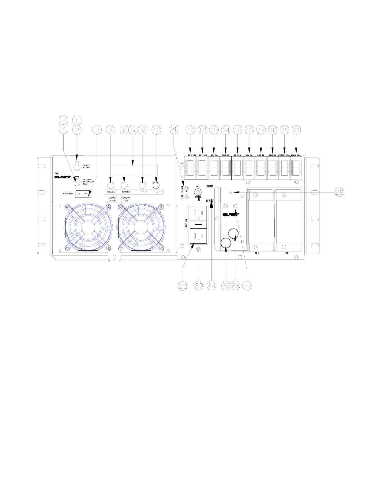
Figure 1: FRONT PANEL VIEW
R
24V D/C TEST
+ POINT -
24V POWER SUPPLY
MODEL PDA24
F2 5A
F1 7A
10

T5
T6
N
C
O
C1
N
N
C
C
O
C2
N ON
C
C
C3
N
N
N
C
C
O
C
C4
SIGNAL
1 2 GND
TEMP. SENSOR
RS232
SNMP
BATTERY CONN.
T1
T2
1 2 43
5
7
6
8910
CR
T4
BATTERY C/B
+24T3GND
+24 GND
24V DC
H N
AC INPUT
G
Figure 2: REAR PANEL VIEW
11

Table 1: FIGURE 1 (FRONT PANEL) DESCRIPTIONS
FRONT PANEL VIEW DESCRIPTIONS
1 COLD START – DC start switch 16 SB4 – Signal Circuit Breaker 4, 5A
2 COLD START INDICATOR 17 SB5 – Signal Circuit Breaker 5, 5A
3
4
5 SYSTEM ON/OFF SWITCH 20 MCB – Main Circuit Breaker, 30A
6 LCD DISPLAY 21 BATTERY TEST POINTS
7 SELECT/MENU MODE 22 GFI RECEPTACLE
8 ENTER/SHOW TIME 23 BYPASS SWITCH
9 UP ARROW + 24 AUTO/FLASH SWITCH
10 DOWN ARROW - 25 F1 – 24VDC Output Fuse, 7A
11
12
13
14
ALARM SILENT/TEST – Dual
function switch
ALARM SILENT/TEST
ACKNOWLEDGE INDICATOR
FL1 – Flash Circuit Breaker 1 –
10 Amp
FL2 – Flash Circuit Breaker 2 –
10Amp
SB1 – Signal Circuit Breaker 1,
5A
SB2 – Signal Circuit Breaker 2,
5A
18 SB6 – Signal Circuit Breaker 6, 5A
19 EQUIP – Equipment Circuit Breaker, 15A
26 F2 – 24VDC Input Fuse, 3A
27 24VDC Test Points
28 24VDC Indicator LED
29 MODEL 204 FLASHER UNIT #1 SLOT
15
SB3 – Signal Circuit Breaker 3,
5A
30 MODEL 204 FLASHER UNIT #2 SLOT
12

Table 2: FIGURE 2 (REAR PANEL) DESCRIPTIONS
REAR PANEL VIEW DESCRIPTIONS
1 T4 - AC INPUT 7 CR – CONTROLLER RECEPTACLE
2 BATTERY CONNECTOR 8 T5 – RELAY CONTACTS
3 BATTERY CIRCUIT BREAKER 9 T6 – OPTIONAL EXT TEMP SENSE
4 T1 - TERMINAL BLOCK 10 RS232 PORT
5 T2 - TERMINAL BLOCK 11 SIGNAL PORT
6 T3 - +24V DC 12 OPTIONAL SNMP CARD
T1 AND T2 PINOUTS
T1-1 GND
T1-2 NEUTRAL
T1-3 NEUTRAL
T1-4 SB5 LINE
T1-5 120V LINE
T1-6 120V LINE
T1-7 FTR
T1-8 SB6 LINE
T1-9 120V LINE
T1-10 GFI LINE
T2-1 GFI NEUTRAL
T2-2 FL1 LOAD 1
T2-3 FL1 LOAD 2
T2-4 FL2 LOAD 1
T2-5 FL2 LOAD 2
T2-6 FTR
T2-7 SB1 LINE
T2-8 SB2 LINE
T2-9 SB3 LINE
T2-10 SB4 LINE
13

SUMMARY OF INDICATORS AND CONTROLS
UPS MODULE
SYSTEM POWER SWITCH - The main control switch that engages utility power to the UPS
module. By activating this switch it initializes normal operation.
COLD START - A momentary push-button switch to activate the system in the event no utility
power is available. The system will be allowed to start up by using power from the battery.
Depress this switch, the indicator above it will light, and hold it in until the audible alarm beeps
once. The system will maintain a load for a period of time depending upon the condition of the
battery. DC INPUT breaker must be ON.
ALARM - This is a fault indicator that will light in the event that the inverter generator is nonoperable. This could be due to an over-temperature situation or an inverter malfunction.
NOTE - Cold Start and Alarm Silent switches must be held in for at least two
!
LCD DISPLAY & PUSH BUTTONS – An LCD Display showing UPS system data, status and
settings. See section 4.
SP170-PDA FRONT PANEL
MAIN 30A BREAKER – 30A circuit breaker that provides power to the system.
EQUIPMENT 15A BREAKER – 15A circuit breaker that provides power to the GFI receptacle.
FL1 & FL2 10A BREAKERS – 10A circuit breakers that provides power to the flasher units.
SB1-SB6 BREAKERS – 5A circuit breakers that provides power to the related outputs on T1 and
T2. These circuit breakers are powered from the Mercury Contactor. When any of the SB1-SB6
breakers are turned off or tripped, the PDA goes into a flash condition.
BATTERY TEST POINTS – Test points to test the actual battery voltage.
BYPASS SWITCH – Switches between UPS power or Bypass power. Must be in UPS position to
have battery back up.
seconds to engage their function. This is to prevent any inadvertent switch
operation.
GFI RECEPTACLE – A ground fault power source. The GFI is powered from the Utility Line. No
Power will be available if Utility Line Power is not available. Must have the Equipment breaker in
the on position to have power here.
14
 Loading...