

Page 1

OWNER'S
OPERATING &
MAINTENANCE
MANUAL
CONTINUOUS POWER SYSTEM
DIGITAL TECHNOLOGY SP-MPL SERIES
Models: SP1250U-MPL
CLARY CORPORATION
150 E. Huntington Dr.
Monrovia, California 91016
Tel. 626-359-4486 HTTP://WWW.CLARY.COM Fax. 626-305-0254
800-44-CLARY E-MAIL [email protected]
Information contained herein is the property of Clary Corporation, is proprietary, confidential, and
not to be disclosed, disseminated or used except for the purpose provided by
CLARY CORPORATION
P/N 510-15138-PR1 01/07
Page 2

TABLE OF CONTENTS PART 1
TITLE PAGE NO.
INTRODUCTION .................................................................................................................3
THE SP-MPL SERIES RACKMOUNT................................................................................4
UNPACKING THE UNIT .....................................................................................................5
PHYSICAL DESCRIPTION.................................................................................................6
SUMMARY OF INDICATORS AND CONTROLS ..............................................................8
SPECIFICATIONS ............................................................................................................10
INSTALLATION ................................................................................................................11
OPERATION .....................................................................................................................12
SIGNALS AND INTERFACING ........................................................................................14
OUTPUT CONTROL .........................................................................................................15
THE BATTERY MODULE.................................................................................................19
CARE AND MAINTENANCE............................................................................................20
SERVICE AND REPAIR ...................................................................................................21
WARRANTY......................................................................................................................22
LIST OF FIGURES PART 1
TITLE PAGE NO.
SP-MPL SERIES BLOCK DIAGRAM.................................................................................4
UNPACKING THE UNIT .....................................................................................................5
RACKMOUNT FRONT VIEW .............................................................................................6
RACKMOUNT REAR VIEW ...............................................................................................7
FRONT PANEL ADJUSTMENT .......................................................................................11
SIGNALS AND INTERFACING ........................................................................................14
Page 3

INTRODUCTION
The following text is a complete product description, operating guide and basic maintenance
summary of the C
This UPS provides a fully on-line sinewave, completely regenerated for typical non-linear loads.
The SP-MPL series has an output rating of 1250VA. The output power factor rating is 0.7, which
means this unit can deliver up to 875 watts.
This instruction manual is provided with this unit to enhance your understanding of the product
and its applications. Read this handbook carefully in the order it is presented prior to operating or
servicing to avoid harm or damage to you or the unit. The UPS may be referred to in the text as
the SP-MPL Series, Rackmount, etc.
LARY SP-MPL Series Rackmount, digital, uninterruptible power system (UPS).
IMPORTANT SAFETY INSTRUCTIONS,
SAVE THESE INSTRUCTIONS
This manual contains important safety instructions that should be followed during installation and
maintenance of the UPS and batteries.
Always operate the unit within the guidelines and specifications presented to maximize this
system's efficiency and lifetime.
Page 3
Page 4
THE SP-MPL SERIES RACKMOUNT
A digital on-line, sinewave UPS is the only total solution to virtually any power problem. It
effectively provides CONTINUOUS POWER, by regenerating the incoming AC to DC and then
back to a highly regulated AC generator. A battery can be provided at the input of the AC
generator to support the load in case of utility interruption. The CONTINUOUS power concept is
a step above the typical power conditioner, in that, power protection is maintained under any
circumstance for the most complete and reliable service to the critical load. This CONTINUOUS
power UPR is designed for the critical, must-not-fail
The Digital Technology (DT) Series rackmount is engineered with the latest Insulated Gate
Bipolar Transistor/Pulse Width Modulation (IGBT/PWM) technology for high efficiency and
reliability. The uninterruptible power system (UPS) is the ruggedized version of the DT family of
products. The electronics are completely governed by an on-board microprocessor. This allows
for not only a digitally processed precision output waveform, but also provides for full interactive
access and control for the user through an RS232 computer port.
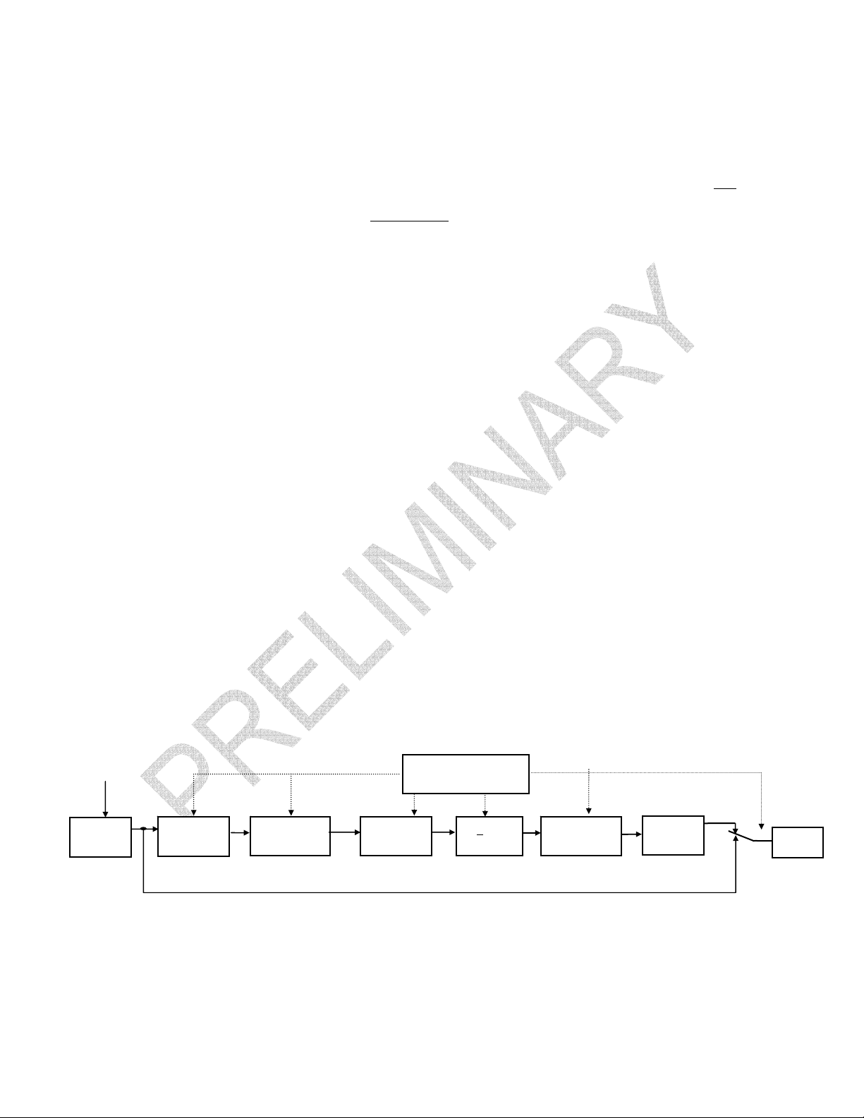
Refer to the simplified block diagram, Figure 1, for system description. An AC source is fed
through a double pole breaker for both Hot and Neutral protection. This breaker then feeds the
power circuits and all internal microelectronics. Input voltage is monitored to allow for operation
over a -25% to +35% range of nominal voltage for all load conditions. An input voltage variation
outside this preset window will discontinue power to the critical load.
The input AC, when it is within this specified window is power factor corrected and then sent to
the rectification stage. The DC rectifier stage provides both positive and negative voltages to a
DC rail stage, which then feeds the digitally controlled inverter AC generator. The AC inverter
generator in turn supplies the load. Normally the output inverter generator is at 60Hz
independent of the input line frequency.
applications.
The DT Series on-line topology is unique to other on-line systems in that it is designed to meet
the needs of all non-linear type loads while providing input power factor correction. Computers
and telecommunications equipment, with their switching power supplies are considered a nonlinear load, which can be very abusive to most power protection equipment and could decrease
life expectancy. The DT Series is specially designed with a power factor corrected input to
eliminate harmonics back into the power source as well as accept non-linear loads and protect
them efficiently without any output waveform degradation common to other UPR designs.
UTILITY INPUT
RFI
INPUT
FILTER
VOLTAGE
WINDOW
DETECTOR
POWER
FACTOR
CORRECTOR
MICROPROCESSOR
RECTIFIER
BYPASS LINE
CONTROLLER
+ DC
RAILS
EMERGENCY
CUTOFF
AC
INVERTER
GENERATOR
COMMON
MODE
CHOKE
SWITCH
LOAD
FIGURE 1: SP-MPL SERIES BLOCK DIAGRAM
Page 4
Page 5
UNPACKING THE UNIT
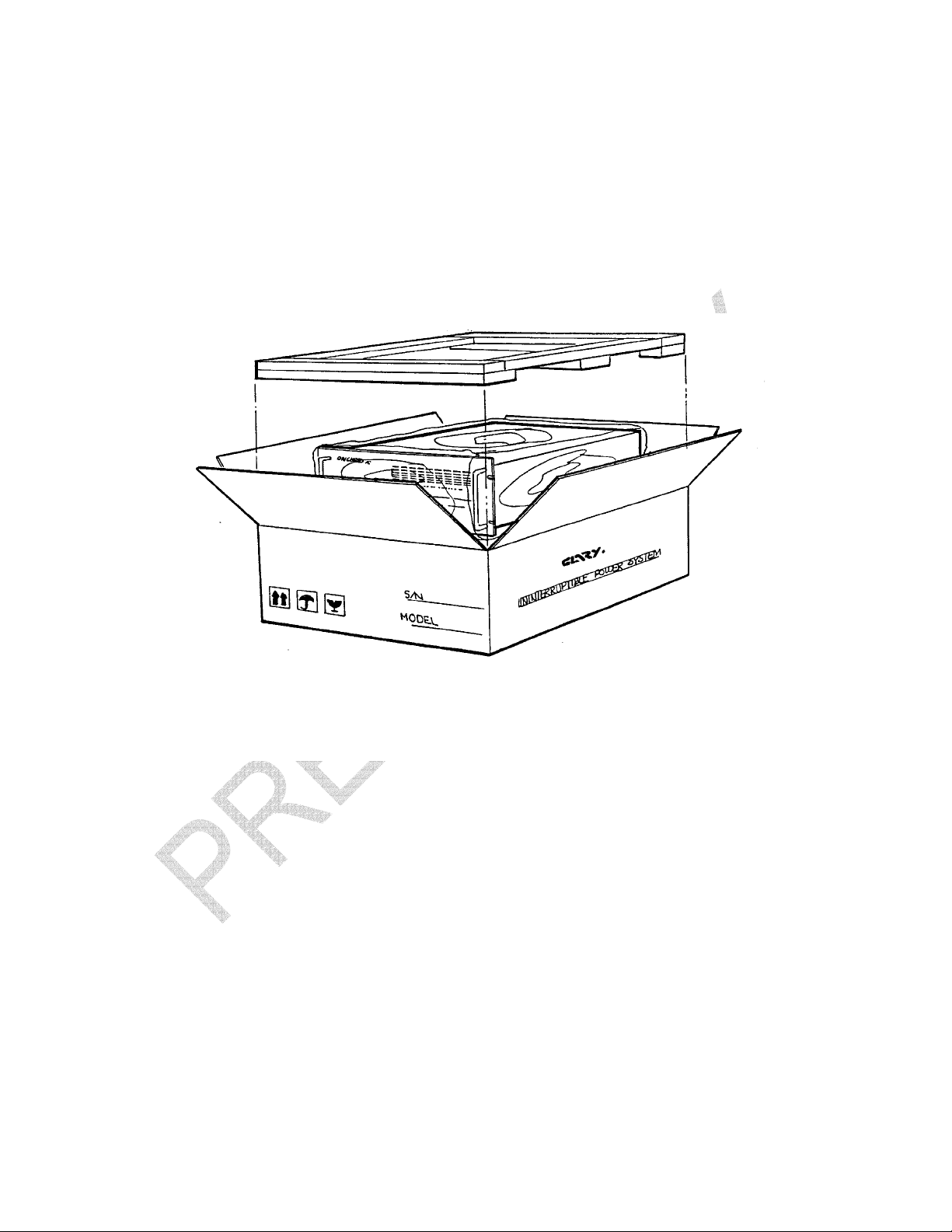
Your UPS has been carefully packaged to withstand most abuse sustained during shipment. If
there is significant damage to the carton, or if there is any physical damage to this unit, report this
to your carrier.
It is recommended to save the shipping container and packaging materials for future transporting,
if necessary. Transporting the unit in other than supplied shipping materials can result in unit
damage not covered by the manufacturer's warranty.
FIGURE 2: UNPACKING THE UNIT
Page 5
Page 6
PHYSICAL DESCRIPTION
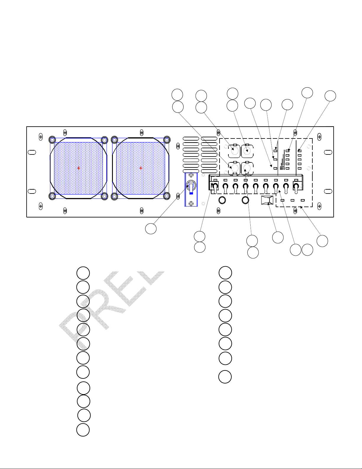
The following illustrations depict the basic Rackmount SP-MPL Series unit. Reference the
SUMMARY OF INDICATORS AND CONTROLS Section for a further description of the call-outs.
FIGURE 3: FRONT VIEW
13
12
8
9
7
6
5
11
10
4
3
OVERRIDE
BYPASS
LOAD
ON/OFF
REPLACE
TEST
AC1
COLD
AC
START
OK
ON
FAULT
BATT
INV
SILENCE
AC4
AC3
AC2
AC6
AC5
INPUT
1
18
CIRCUIT BREAKERPOWER
19
DC3DC1/2
ON
14
SYSTEM
OFF
2
15
BATTERYSTATUS
FAIL
FAN
DC1/2
OUTPUT
FULL
LOW
DC3
WARM
TEMPERATURE
16
HOT
OVER
100%
75%
50%
25%
20
17
1 INPUT POWER SWITCH 13 REPLACE BATTERY LED
2 SYSTEM ON/OFF SWITCH 14 ALARM RESET SWITCH
3 LOAD LEDs 15 FAULT LED
4 BATTERY LEDs 16 LOAD SWITCHES AC1 – AC8
5 AC IN OK LED 17 LOAD LEDS AC1 – AC8
6 ON BATTERY LED 18 OVERRIDE SWITCH
7 INVERTER LED 19 OVERRIDE LED
8 COLD START SWITCH
9 COLD START LED
20
FAN FAIL, TEMP WARM & HOT
NOT USED IN THIS MODEL
10 LOAD ON/OFF SWITCH
11 BYPASS LED
12 BATTERY TEST SWITCH
Page 6
Page 7
30
24
AC7 AC5
AC8
SNMP
32
31
AC6
25
AC3 AC1
AC4
RS232
SIGNAL
26
DC INPUT
29
AC2
AC INPUT
27
GND
28
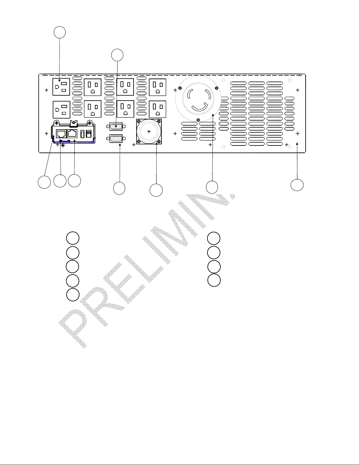
FIGURE 4: RACKMOUNT REAR VIEW
24 OUTPUT- AC1-8 29 DC INPUT
25 RS232 CONNECTOR 30 SNMP CARD
26 SIGNAL CONNECTOR 31 SNMP - LAN
27 AC INPUT 32 SNMP - COM
28 GROUND STUD
Page 7
Page 8

SUMMARY OF INDICATORS AND CONTROLS
UPS FRONT PANEL
INPUT POWER SWITCH - This is system input AC power protection and interruption for
both hot and neutral lines. This circuit breaker is rated at 20A.
SYSTEM ON/OFF SWITCH - This is system input enable switch. This switch is used to
power down the system. This switch must be in the ON position in order to start the UPR.
LOAD LEDs - Four green L.E.D.s and one red OVERLOAD L.E.D. that illuminate to update
status of the amount of load the INVERTER is powering at the UPS system output. Each green
L.E.D. represents approximately 25% of full load. As more load is added to the UPS, the L.E.D.s
will sequentially turn "ON" until the red L.E.D. comes "ON". This indicates an OVERLOAD
situation and the system will discontinue operation shortly.
BATTERY LEDs - Four green L.E.D.s and one green LOW BATTERY L.E.D. that illuminate
to update status of the battery energy available during a power outage. Each green L.E.D.
represents approximately 20% of battery reserve power available. As battery discharge
continues, the L.E.D.s will sequentially turn "OFF" until the last L.E.D. starts to flash. This
indicates a LOW BATTERY situation and the system will discontinue operation shortly. Once
utility power is returned to the system, this bar graph will show an approximate battery state as it
reaches full charge. The top L.E.D. indicates charger on/off when unit running on AC. L.E.D. ON
Charger OFF, L.E.D. OFF Charger ON.
AC IN OK LED- A green L.E.D. that is illuminated when the AC input is within operating limits.
ON BATTERY LED - A red L.E.D. that is illuminated when the AC input is interrupted to the
power electronics either externally or internally from the microprocessor due to an out-of-range
situation. The output load is then supported entirely by battery energy through INVERTER
operation.
INVERTER LED - A green L.E.D. that illuminates when the INVERTER generator is operating.
COLD START SWITCH - This is a momentary, two position push button switch. If no AC
utility voltage is available, it may still be a requirement to initialize some equipment. When this
switch is pressed in for at least two seconds, the system will start up on battery power. The
SYSTEM ON/OFF Switch must be in the ON position for this function to operate. The green
L.E.D. above this switch will light only while the switch is held in.
COLD START LED - A green L.E.D. that illuminates when the cold start switch is pressed.
LOAD ON/OFF SWITCH - Push button switch that enables output circuits when turned ON,
disables output circuits when turned OFF.
BYPASS LED
system output is operating in the filtered, emergency BYPASS mode.
- A red L.E.D. above the LOAD ON/OFF SWITCH will light to indicate when the
BATTERY TEST SWITCH - This is a momentary, two position push button switch. Battery
condition is vital to the UPS performance, particularly during a power outage. During normal
operation with inverter ON, load applied to the unit and the Battery Bar Graph showing the
battery at a full charge, this function switch may be used. By pressing this switch in for at least
two seconds, a battery acceptance diagnostic will be run by the internal microprocessor.
Page 8
Page 9

REPLACE BATTERY LED - After the battery acceptance diagnostic test has discovered
that the batteries are excessively fatigued, the red L.E.D. above this switch will light advising the
user that the Batteries are bad and should be replaced or battery module is not connected to the
UPS. During battery test this LED will flash red for approx. 30 seconds.
ALARM RESET SWITCH - This is a momentary, two position push button switch. During a
system FAULT or power failure, an audible alarm will be present. Once this switch is pressed in
for at least two seconds, the audible alarm will be silenced. The L.E.D. above the switch will
remain unchanged.
FAULT LED - If a FAULT condition occurs, this red L.E.D. will illuminate.
LOAD SWITCHES AC1 - AC8 – Locking switches that turn on and off corresponding AC
outputs.
LOAD LEDS AC1 - AC8 – Green illumination indicates load is available at corresponding
outputs.
OVERRIDE SWITCH – When this locking switch is turned on, load switches (Loads 1-8) can
only be activated manually. You will not be allowed to control the load switches through the
SNMP with this switch activated.
OVERRIDE LED – Red illumination indicates override switch is turned on.
UPS REAR PANEL
AC OUTPUTS – Eight(8) NEMA 5-15R connectors provided for 120VAC output. Continuous
power is provided here and is monitored by the LOAD L.E.D.s as long as the INVERTER is
functioning. The Loads ON/OFF Switch and the corresponding Load Switches on the Front panel
must be enabled for power to be present at AC1-AC8.
RS232 CONNECTOR - DB-9 subminiature female connector provided for intelligent
computer monitoring systems. See SIGNALS AND INTERFACING Section for specific pin-outs.
SIGNAL CONNECTOR - DB-9 subminiature female connector provided for open collector
alarms. See SIGNALS AND INTERFACING Section for specific pin-outs.
INPUT – One L5-20P inlet connector for AC input.
GROUND - A 10-32 x 3/4 threaded stud for system rack grounding.
SNMP INTERFACE - An add-on card that provides Simple Network Management Protocol
(SNMP) access to the UPR controller via a RJ45 connector (LAN). The second RJ45 connector
(RS232) provides a second RS232 port to the controller.
DC INPUT – A circular locking connector provided for battery power to the UPS. This
UPS uses a 96V System.
NOTE – For safety purposes, the DC INPUT connector is tied into an
!
interlock system which ensures that if the connector is disconnected, the
unit will discontinue operation.
Page 9
Page 10

SPECIFICATIONS (Preliminary)
ELECTRICAL
Input
Voltage 120VAC +35%, -20%
Frequency 60Hz or 50Hz
Current 20A Max @ 120VAC
AC Output
Voltage(AC) 120VAC +3%
Current, Watts 1250VA(875W) @ 0.7pf
Frequency 60Hz or 50Hz +.25% (software selectable)
Crest Factor Ratio
(Non-linear load and
less than 5% THD) Typical
Harmonic Distortion 5% Max. THD
Dynamic Response +4% for 100% Step Load Change, 0.5 Millisecond Recovery Time
Overload 110% for 10 Minutes; 200% for 50 milliseconds
Efficiency (UPS)
Load Power Factor
UPS Protection Input and Output Short Circuit; Input and Output Overload;
CONTROLS AND INDICATORS
Visual Indicators
Audible Alarms Utility Interrupt, Inverter Failure, Overload, Low Battery, fan fail, warm and
Intelligent Computer Interface
(DB-25F)
DESIGN
Standard Features Regenerative
ENVIRONMENTAL
Operating Temperature 32oF to 122oF (0oC to 60oC)
Humidity 0% to 95% non-condensing
Altitude Sea Level to 10,000 Feet
MECHANICAL
Input L5-30P Inlet connector
AC Output (AC1-AC8) (8) NEMA 5-15R connectors
Overall Dimensions L x H x W 18.5 in x 5.25 in x 19 in.
Weight 40lb. (18.2 kg)
Cooling Low Velocity, Forced Air
@50% Load Up to 4.8:1
@75% Load Up to 3.2:1
@100% Load Up to 2.4:1
85%
0.7
Battery Level, Load Level, AC Input, Inverter, Battery On, Bypass On,
Cold Start, Fault, Replace Battery
overtemp.
Full Interactive, Remote Computer Monitoring and Control of
UPS Functions (RS232 Interface);
Open-collector Alarm Signals interface to control panel
TM
On-Line, Sinewave Inverter Powers Load Continuously
Extended Brownout Protection, High Frequency, Digitally Controlled IGBT
PWM, Power Factor Corrected on Input, Designed for Non-linear Loads,
Continuous Operation on +35% Line
Page 10
Page 11

INSTALLATION
This Rackmount system is designed for installation in a protected environment. This system may
be installed in a 19" rack system. Some important points to consider when positioning a unit for
operation:
• A 20A (preferably dedicated) outlet is accessible for the power connection to the unit. It
is not recommended to modify the power cord in any way nor should an extension cord
of any kind be used. Never use a surge protected device on the output of this
system.
• The cord paths in the system installation should remain clear of foot traffic or anything
else that may disturb permanent connection.
o
• The installation site should maintain an ambient air temperature of less than 140
o
C). When the environment for the system remains cooler during operation, there is
(60
less stress on the batteries and the internal electronics.
• The air inlets, vents and fan should not be obstructed or blocked in any way. The more
breathing space the system has, the cooler it operates.
• The air should remain free from excessive dust and chemical fumes.
F
• The front panel is designed to fit in a standard 19" rack. This panel fills a 5.25
inch (3U)
slot. Guide Rails or slides are recommended to support the unit's mainframe. This
system can weigh in access of 40 pounds, therefor front panel mounting is not intended
to support the entire unit. The system comes with pre-tapped aluminum slide bars to
accept Jonathan QD-145 slides. Separate shims are included for correct slide bar
spacing if the unit is installed in a DTC-2 (C3) rack.
Once a location has been selected and the unit is installed, it is ready for operation.
Once the unit is installed into a rack, small adjustments may be required for the front panel to
screw mount into the frame. Refer to the following steps and diagram to adjust the panel to the
desired position:
1) Loosen, but do not remove, all screws holding in the front panel.
2) Loosen, but do not remove, the four acorn nuts on the handles.
3) The entire front panel should now have limited play for exact positioning.
4) Install the four panel mounting screws in front panel slots into the rack enclosure.
5) Retighten all
screws and nuts that you have loosened.
OVERRIDE
BYPASS
LOAD
ON/OFF
REPLACE
TEST
AC1
OUTPUT
COLD
START
FAULT
SILENCE
AC4
AC3
AC2
BATTERYSTATUS
AC
OK
ON
BATT
INV
AC5
FULL
OVER
100%
75%
LOW
50%
25%
AC6
DC1/2
DC3
INPUT
DC3DC1/2
CIRCUIT BREAKERPOWER
FIGURE 6: FRONT PANEL ADJUSTMENT
Page 11
FAIL
FAN
OFF
SYSTEM
ON
TEMPERATURE
HOT WARM
Page 12

OPERATION
Be sure the power cord is plugged into an appropriately rated outlet.
Activate the INPUT ON/OFF Circuit Breaker to the “ON” position on the UPS.
Activate the SYSTEM ON/OFF Switch to the “ON” position on the UPS.
The system will go through a diagnostic test routine.
The green AC IN OK L.E.D. will flash several times before it illuminates solid.
The audible alarm will sound a short burst.
The AC INV L.E.D. will illuminate and the loads AC1-8 will illuminate.(if Load switches are in
the “ON” position).
Activate the SYSTEM ON/OFF Switch to the “OFF” position to discontinue system operation.
Turn off the devices you wish to plug into the UPS. Connect them to the output at the rear of the
unit. Do not exceed the output ratings of the system.
Activate the SYSTEM ON/OFF Switch to the “ON” position.
The system will go through a diagnostic test routine and test all the L.E.D.s.
Push and hold in the LOAD ON/OFF Switch for at least two seconds.
The AC OUTPUT L.E.D. will illuminate indicating output power is available at the rear panel
outlets.
Turn “ON” the Load Switches on the Control Panel.
Turn “ON” each of your devices.
Some of the four green L.E.D. LOAD indicators should illuminate. The amount of load is
determined by the actual number of indicators lit.
Each L.E.D. signifies approximately 25% of load capacity. If all four L.E.D.s illuminate, full load
has been achieved. If the red light illuminates, an OVERLOAD condition is present. If this
situation continues beyond three seconds, the unit will automatically shut off, discontinuing all
operation including the output to the load. The red FAULT L.E.D. will light and a continuous
alarm will be heard. The load must be reduced and the SYSTEM ON/OFF Switch will have to be
reset in order to return to normal operation.
If the system overheats or the INVERTER should fail, the unit automatically transfers power to
the BYPASS line to maintain uninterrupted power to the load. The red BYPASS L.E.D., above
the LOAD ON/OFF Switch, will light. A continuous alarm will sound and the red FAULT L.E.D.
will illuminate.
To escape this condition, the problem must first be corrected, then the
must be reset.
The ALARM RESET Switch on the front panel of the UPS can be used at any time to silence the
audible alarm. This switch must be held in for at least two seconds before the alarm will quiet.
The FAULT L.E.D. above this switch will remain unchanged while operating this switch.
SYSTEM ON/OFF Switch
Page 12
Page 13

Battery Operation after AC Start-Up:
Turn Off the Circuit Breaker on the Front Panel of the UPS.
The AC ON light will flash at two to three second intervals. Within 5 seconds, the audible alarm
will sound at half-second intervals.
Push and hold in the ALARM SILENT/TEST switch until the audible alarm is inhibited.
If operation were to continue in this mode, the battery level meter would start to turn OFF, one
light at a time starting from the top. Once the last light is left and the preprogrammed battery
availability time (usually about 2 minutes) is reached, the alarm will sound in a constant tone.
Had the alarm been previously silenced, it would still re-enable to alert the user of limited
operation. This alarm can also be silenced as before. If the unit is allowed to operate further, it
will time out and shut off completely. If power were to return, the unit will automatically restart
and return to the condition it was in at the moment it went into Battery Mode.
DC Start Operation (Cold Start)
If no utility power is available at the time backup power is required, the unit may be started to
accomplish abbreviated tasks. The limitations of the battery prevent extended operations at full
load.
Position the System Power Switch to the ON position.
Push and hold in the cold start switch until the audible alarm beeps.
The unit will start up similarly to normal AC start-up except the AC IN LED will continue to flash.
The LOAD outputs will come up in the off mode when using the cold start feature.
Page 13
Page 14

SIGNALS AND INTERFACING
This system is designed to be compatible with most sophisticated operating systems when they
feature a UPS monitoring function. These signals are made available through the DB-9
subminiature female connector at the rear of the UPS. The communications connector at the
rear of the UPR is for a RS232 interface connection. The Signal connector features opencollector alarm signals. Closing the points between pins 6 and 8 while running on battery will
shutdown the UPS. Below is a diagram of the signal jacks and their pin-outs:
RS232 CONNECTOR
1- LOW BATTERY/
2- TX
3- RX
4- DTR
5- GROUND
6- DSR
7- RTS
8- AC FAIL/
NOTE: Pins 4 and 7 enable relays on the Interface board that allow communications directly with
the UPS from the RS232 Connector. When relays are enabled, SNMP is disabled.
SIGNAL CONNECTOR
2- AC FAIL
3- UPS ON
4- GROUND
5- LOW BATTERY
6- REMOTE SHUTDOWN+
7- REMOTE SHUTDOWN (RETURN)
8- +9VDC
Page 14
Page 15

Output Control
The SP-MPL series has eight AC outlets (AC1-AC8). The outlets can be controlled individually by the
operator either locally via the front panel switches or remotely thru the SNMP card.
To remotely control the eight AC outlets you must first set up and connect to the SNMP card. See
instructions on SNMP/WEB Agent disk for setup.
Once connected, Click on the NPM icon.
Page 15
Page 16

The NPM Status screen allows you to monitor the status of the eight outlets.
Page 16
Page 17

The NPM Setup page allows you to setup the various settings for each outlet. From this page you can
rename each outlet as you wish.
The configuration page allows the user to set the time for the Action timer and the default timer.
Page 17
Page 18

The NPM Control screen allows you to control each individual outlet or all at once.
You can turn On or Off the loads from this page. Also available is the feature to cycle each load. The
timers are set in the NPM Setup page.
Page 18
Page 19

The Battery Module.
The SP1250U and SP1500U batteries are comprised of one or more strings of 6 individual 12V
batteries connected in series for a total string voltage of 72V DC nominal. The SP2000U-MPL
batteries are comprised of one or more strings of 8 individual 12V batteries connected in series
for a total string of 96V DC nominal.
The batteries are extreme temperature, deep cycle, AGM/VRLA (Absorbed Glass Mat/ Valve
Regulated Lead Acid) batteries that have been field proven and tested by the U.S. military. The
OutPost
temperatures from –40C to +74C.
The batteries are provided with appropriate interconnect wiring harness. Optional battery
mounting trays and brackets are available.
The interconnect cable connects to the base module via a quick-release circular connector.
The UPS module includes a charger that replenishes the Battery Pack whenever possible and
required. This charger operates with a maximum charging current of 0.6A at 96V. An optional
“Fast Charger” module plugs into the UPS module to increase the charging current to over 3.5A.
CLARY OutPost
TM
batteries supplied by Clary Corporation are certified to operate at extreme
TM
BATTERIES*
Estimated Runtime
(Per set @ 77°F / 25°C)
(New Batteries, fully charged)
Clary
Part. No.*
OP96C
(Set of 8
Batteries)
Volts/
A-hrs.
12
VDC/
41 AH
300
Watts
8.5
Hrs.**
700
Watts
3.5
Hrs.**
1050
Watts
1.5
Hrs.**
1400
Watts
1.0
Hrs.**
Unit
Weight Per
Battery
Lbs.
(Kg.)
29
(13.2)
Overall Dimensions
Per Battery Inches (cm.)
Length L WidthW Height
7.68
(19.6)
5.15
(13.1)
*OP96X battery sets include eight (8) batteries per set. Wired in series, each set
provides 96 VDC.
**Actual times may vary. Runtimes are dependent on many factors.
Lower/Higher AH capacity batteries, allowing less or more runtime, are available on
special order. Call factory for more information.
H
7.9
(20.1)
Page 19
Page 20

CARE & MAINTENANCE
This system is designed to be maintenance-free. It can be cleaned with a damp cloth or nonabrasive cleanser.
Be sure filters and vents are kept free from accumulation of dust, dirt or lint.
If system cooling is not adequate, operation or reliability may be affected. The system is normally
assembled with the flow of cool air being pulled in the front panel and exhausting warm air out
the rear. If in final installation this air path conflicts with the entire rack, the air flow may be
reversed. Reference the following procedure for a step-by-step explanation.
1. Remove all power from the unit.
2. Remove the top cover.
3. Remove the eight knurled nuts and the two fan filters.
4. Remove the handles.
5. Remove the six screws holding in the front panel. You should now be able to reach the
screws holding the fans to the front panel.
6. Remove the red and black wires from the board to the fans.
7. Remove the eight screws holding in the fans.
8. Reverse the fans and put screws back into place.
9. Plug in the red and black wires. (FC1 &FC2)
10. Place front panel back into place and check to make sure no other cables are disconnected.
11. Put the 6 screws back into place.
12. Reinstall Handles.
13. Reinstall the two fan filters and the knurled nuts.
14. Before installing the top cover, visually inspect the unit for any loose hardware.
Page 20
Page 21

SERVICE AND REPAIR
This SP-MPL Rackmount is backed by one of the finest customer service teams assembled.
Write or call them at any time to obtain information about your unit.
Clary Corporation
150 E. Huntington Dr.
Monrovia, CA 91016
626-359-4486
800-551-6111
[email protected]
If a problem should occur, it is important that you obtain a Return Material Authorization (RMA)
number from the Service Department to process any unit returned to the factory. In consulting
the factory, always have the unit model number and serial number at hand. This information is
located on the identification label on the left side and is essential in retrieving your units
performance and history record.
The RMA number issued to you should appear on the outside of the carton, if the unit is returned,
or on any correspondence regarding your unit. When shipping a unit back to the factory, try to
use the original packing container and shipping materials. Shipping materials are available
through the Service Department if the original container is unobtainable. The Service
Department cannot take responsibility for any unit damaged in return shipment. All units must be
returned prepaid to:
CLARY SERVICE DEPT.
150 E. Huntington Dr.
Monrovia, CA 91016
FCC CONSIDERATIONS
This equipment generates and uses radio frequency energy and if not installed and used properly in strict
accordance with the manufacturer's instructions, may cause interference to radio and television reception. The
unit in this manual has been tested and found to comply with the limits for a Class A computing device in
accordance with the specifications in Subpart J of Part 15 of FCC Rules, which are designed to provide
reasonable protection against such interference in a commercial installation. However, there is no guarantee
that interference will not occur in a particular installation. If this equipment does cause interference to radio and
television reception, which can be determined by turning the equipment off and on, the user is encouraged to try
to correct the interference by one or more of the following measures:
• Reorient the receiving antenna.
• Relocate the UPS with respect to the receiver.
• Move the UPS away from the receiver.
• Plug the UPS into a different outlet so that the UPS and receiver are on different branch circuits.
If necessary, the user should consult the dealer or an experienced radio/television technician for additional
suggestions. The user may find the following booklet prepared by the Federal Communications Commission
helpful:
"How To Identify and Resolve Radio-TV Interference Problems"
This booklet is available from the U.S. Government Printing Office,
Washington, DC 20402, Stock No. 004000003454.
Page 21
Page 22

WARRANTY
1. TIME AND SCOPE OF WARRANTY:
1.1 CIary Corporation hereby warrants all equipment shipped under this Agreement to be free from defective
components and workmanship for a period of 2 years following date of shipment. Accidental damage,
misuse or normal wear shall not be construed as a defect.
1.2 The date of shipment as used herein will be the date on Clary’s Bill of Lading. If no Bill of Lading is
issued, the date of shipment shall be shown on seller's shipping document.
1.3 No provision of this warranty shall cover equipment, which has been altered or modified from the original
specifications to which it was manufactured, unless authorized in writing.
1.4 No provision of this warranty shall cover batteries. However, battery manufacturer’s warranties will be
passed through to the customer whenever applicable.
2. LIMITS OF "IN-WARRANTY" SERVICE LIABILITY
2.1 Clary is obligated during the in-warranty period to provide service and/or adjustments to equipment
returned to the factory at the expense of the buyer. (The term “factory” as used herein shall also include
any field service centers, which may be established by Clary.) Clary is to repair or replace any part(s)
thereof, which in the opinion of authorized Clary personnel are found to have been defective.
2.2 Equipment requiring in-warranty service must be returned to the factory with all transportation charges
prepaid. Equipment must be clearly tagged stating the nature of the trouble experienced and the
disposition of the equipment after repair. The equipment will be returned freight collect by Clary to the
location specified via the best, least expensive carrier available, or via customer's shipping instructions.
2.3 The nature of certain equipment installations may be such that it would be impractical or technically
infeasible to remove the Clary portion of the equipment from the customer's premises to the Clary factory.
In such cases, and at the request of the buyer, Clary will perform such service as can be satisfactorily
rendered at buyers location. The buyer will be charged only for travel expenses incidental to the service
call, provided that the warranty is applicable.
2.4 During the in-warranty period, no service charges shall be payable by the buyer for service performed
other than for service necessitated by accident, misuse, theft, abnormal line or source voltage
fluctuations, abnormal conditions of operation, damage by the elements or damage resulting from
adjustments, repairs, modifications made by other than Clary Authorized personnel, or the buyer's failure
to reasonably maintain the equipment
THE FOREGOING WARRANTY IS EXCLUSIVE AND IS GIVEN AND ACCEPTED IN LIEU OF ANY AND
ALL OTHER WARRANTIES, EXPRESSED OR IMPLIED. INCLUDING WITHOUT LIMITATION THE
IMPLIED WARRANTIES OF MERCHANTABILITY AND FITNESS FOR A PARTICULAR PURPOSE. THE
REMEDIES OF BUYER SHALL BE LIMITED TO THOSE PROVIDED HEREIN. IN NO EVENT WILL
SELLER BE LIABLE FOR COLLATERAL OR CONSEQUENTIAL DAMAGES. No person is authorized to
assume in behalf of Clary any obligation or liability in connection with the sale, warranty or service policy of
any products manufactured and/or marketed by Clary Corporation beyond the warranty description on the
face hereof.
3.1 Clary Corporation reserves the right to make changes, additions. and/or improvements in its products
without incurring any obligation to install them on its products previously sold.
Page 22
 Loading...