

Clary SP1250 LE User Manual

PRELIMINARY
Owner’s
Operating
Manual
SP SERIES
CONTINUOUS POWER SYSTEM
MODELS COVERED:
SP560
SP1250LE
CLARY CORPORATION
150 E. Huntington Dr.
Monrovia, California 91016
Telephone
Fax.
Web
626-359-4486
800-44 CLARY
626-305-0254
HTTP: // www.clary.com
Information contained herein is the property of Clary Corporation, is proprietary, confidential, and not to be
disclosed, disseminated or used except for the purpose provided by
CLARY CORPORATION
P/N 510-16126 REV. NR -Date: 04/12 E.O. 413597

TABLE OF CONTENTS
T H E C O N T I N U O U S P O W E R C O M P A N Y
TITLE PAGE
TABLE OF CONTENTS 2
INTRODUCTION 3
TECHNICAL DESCRIPTION 4
PACKAGING 5
PHYSICAL DESCRIPTION SP560 6
PHYSICAL DESCRIPTION SP1250LE 7
INSTALLATION 9
OPERATION 10
SIGNALS AND INTERFACING 11
USB SETUP 12
SPECIFICATIONS 15
BATTERY PACK (SP-48SB) 16
BYPASS BOX (SPH-302) 17
CARE AND MAINTENANCE 19
SERVICE AND REPAIR 20
WARRANTY 21
C
This symbol indicates that there
INTRODUCTION
ongratulations! You have selected the
highest quality protection for your continuous
power needs. This unit offers a quiet and
compact package with superior performance you can
depend on. You now own a SP Series Continuous
Power System (CPS) which is an all Digital
Technology product manufactured by Clary
Corporation, the first name in uninterruptible power
system (UPS) reliability. The Continuous Power
System is the highest order in the hierarchy of UPS
products. When power problems occur, there can
be no compromising the reliability of your power
solution. The SP Series Continuous Power System
is your complete power solution.
This Owner’s Operating Manual is provided with your
new SP Series UPS. It will enhance your
understanding of the product and its functions. WE
STRONGLY URGE YOU TO READ THIS MANUAL
COMPLETELY, PRIOR TO BEGINNING
INSTALLATION OR ATTEMPTING OPERATION.
This will save you time and effort in your installation
and application, and it will assure a trouble free
installation and startup session, thus enhancing
public safety and the image of your agency.
The illustrations provided will familiarize you with this
product’s operating modes and components. Always
operate the unit within the guidelines and
specifications provided to maximize safety and the
lifetime of the unit. Also, your understanding of the
product is a key element in getting the most out of
your SP Series UPS.
IMPORTANT SAFETY INSTRUCTIONS,
SAVE THESE INSTRUCTIONS
This symbol indicates that
dangerous voltage constituting
a risk of electrical shock is
present within the unit.
This manual contains important safety instructions that should be followed during installation and maintenance of
the UPS and batteries. Be aware of the following symbols and their meaning as they appear throughout the
manual:
are important operating and
maintenance instructions in the
!
literature accompanying this
unit.
CAUTION
RISK OF ELECTRIC
SHOCK DO NOT OPEN
!
Page 3

T
TECHNICAL DESCRIPTION
he Digital Technology-Extreme Temperature
SP560/SP1250LE Series Continuous Power
System (CPS) is a revolutionary new concept in total
power protection and management. The
SP560/SP1250LE Series is a DSP processor-based
UPS that allows the user to set most of the control
feature parameters. By directly linking a personal
computer to the SP560/SP1250LE Series Com
ports, frequency settings and operation, alarm
signals, load switching, fan operation, etc. can all be
programmed to meet specific application
requirements.
The SP560/SP1250LE Series is a true on-line,
continuous power UPS. In the tradition of Clary
products, the SP560/SP1250LE Series generates
the same high quality and proven reliability to provide
the best power protection available for today’s critical
applications.
In keeping with the state-of-the-art design, the power
electronics are completely governed by an on-board
DSP based processor. Given the powerful
processing capability of today’s DSP chips, this
allows the UPS to evolve into an all-in-one complete
power distribution and monitoring center. Not only is
your critical load insured of the most reliable and
constant power available, but the user may now
continuously monitor the status of the various
operational parameters in the system.
The AC utility source is connected to the power
switching and control electronics when the input
switch is closed. The input line is filtered, rectified
and power factor corrected for enhanced
performance without disturbing other equipment that
may share the same utility circuit.
The DSP processor controls an Inverter Generator
that produces a clean, low harmonic, AC output
sinewave for continuous power applications.
When the input AC utility line fails, the battery circuit
within this system takes over to ensure continuous
power. Only when properly rated input power is
returned, does the unit reconnect the input source
back to the system.
The unit is connected to a Com port which allows the
user to monitor and set operating parameters. W ith
a simple link to a personal computer using the
“SP560/SP1250LE UPS software program”, the user
can view the event history of the power distribution
system. More sophisticated users may choose to
implement the optional SNMP package to allow full
Network Power Management capability.
Page 4
Y
PACKAGING
our UPS has been carefully packaged to
withstand most abuse sustained during
shipment. The packing material has been
specifically designed to protect this system for
normal handling, using most shipping carriers. If
there is significant damage to the carton, or if there is
any physical damage to this unit, report this to your
carrier.
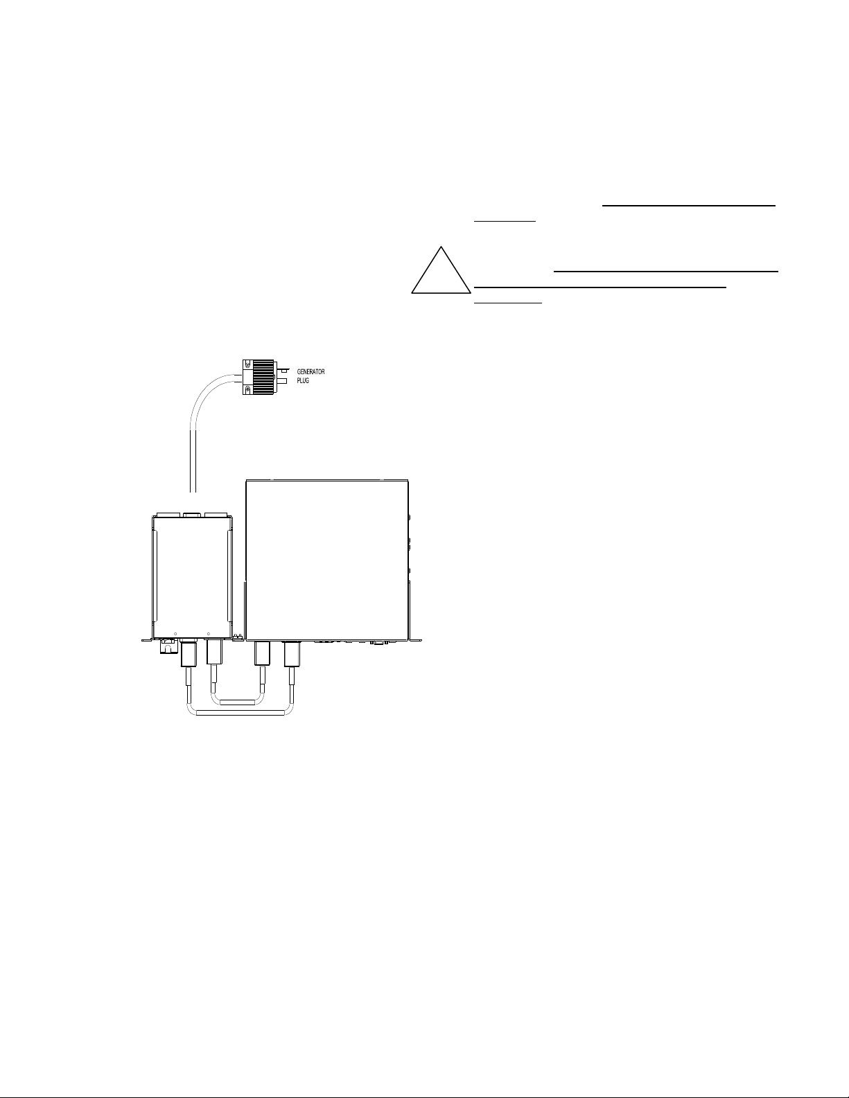
These units are encapsulated in a protective wrap
that comes apart once the product is removed from
the shipping carton. Save all packing material for
future use.
The packaging also contains important information
on use and care as well as valuable warranty
information. Read all materials before storing this
!
literature with your other valuable product
documents.
SPH-302
BYPASS-SWITCH
Page 5
T
PHYSICAL DESCRIPTION SP560
his section will point out and illustrate the
various indicators, functions and controls of
the SP560 and SP1250LE Series UPS. The
important attributes of the SP560/SP1250LE Series
unit are numbered to assist you in locating them on
your machine and also to fully explain its function
and how it relates to system operation.
Numbers on the drawing will correspond to the
operating component’s name at the bottom with a
brief identification. In the next section, a complete
explanation of all numbered items will be enhanced
to ensure you have a full understanding of the
visual indicators used on the front panel are long
lasting, very efficient, light emitting diodes (LED).
When operating the push-button switches, always
hold the switch in for at least two seconds to insure
function confirmation. This feature has been
implemented into the system design to avoid
inadvertent operation of any of the user-available
functions.
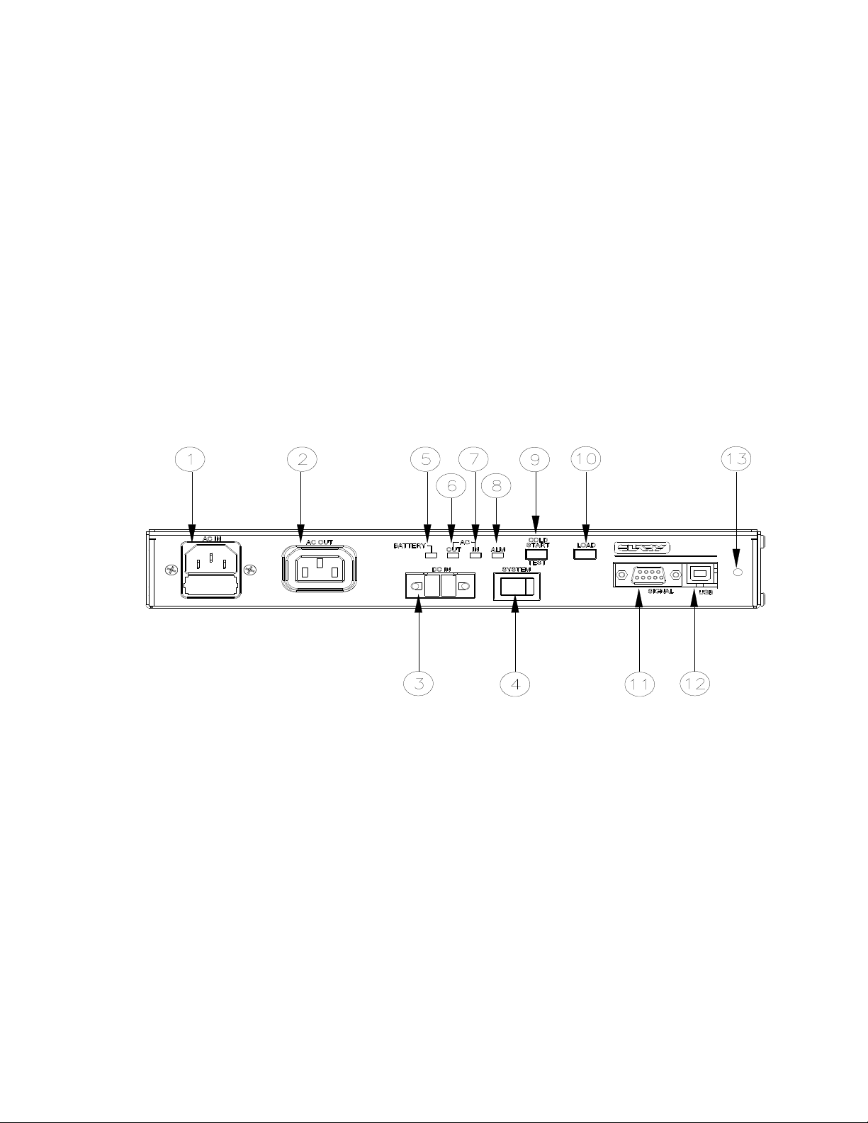
Pictured below is the front view of the model SP560.
SP560 FRONT PANEL VIEW
1 AC IN 7 AC IN LED
2 AC OUT 8 ALARM LED
3 DC IN 9 COLD START/TEST SWITCH
4 SYSTEM SWITCH 10 LOAD SWITCH
5 BATTERY LED 11 SIGNAL DB9
6 AC OUT LED 12 USB TYPE B
13 PROGRAM SWITCH
Page 6
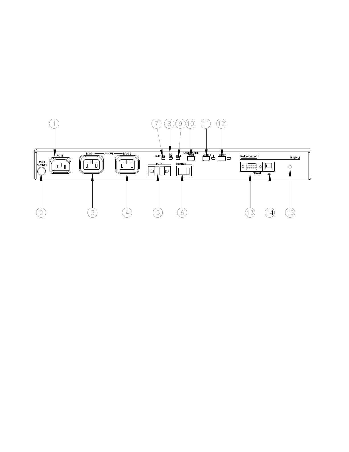
PHYSICAL DESCRIPTION SP1250LE
1 AC IN 8 AC IN LED
2 AC IN FUSE 9 ALARM LED
3 AC OUT – LOAD 1 10 COLD START/TEST SWITCH
4 AC OUT – LOAD 2 11 LOAD 1 SWITCH
5 DC INPUT 12 LOAD 2 SWITCH
6 SYSTEM SWITCH 13 SIGNAL DB9
7 BATTERY LED 14 USB TYPE B
15 PROGRAM SWITCH
SP1250LE FRONT PANEL VIEW
Page 7
 Loading...