

Clary CMN2400D-PD User Manual

OWNER'S
OPERATING &
MAINTENANCE
MANUAL
CONTINUOUS POWER SYSTEM
DIGITAL TECHNOLOGY CMN SERIES
2400VA
Model: CMN2400D-PD
CLARY CORPORATION
150 E. Huntington Dr.
Monrovia, California 91016
Tel. 626-359-4486 HTTP://WWW.CLARY.COM Fax. 626-305-0254
800-44-CLARY E-MAIL SALES@CLARY.COM
Information contained herein is the property of Clary Corporation, is proprietary, confidential, and
not to be disclosed, disseminated or used except for the purpose provided by
CLARY CORPORATION
P/N 510-15176-NR E.O.# 412359 10/9/07

TABLE OF CONTENTS PART 1
TITLE PAGE NO.
INTRODUCTION .................................................................................................................3
THE CMN SERIES RACKMOUNT .....................................................................................4
UNPACKING THE UNIT .....................................................................................................5
PHYSICAL DESCRIPTION.................................................................................................6
PINOUTS FOR CONNECTORS .........................................................................................8
SUMMARY OF INDICATORS AND CONTROLS ............................................................10
CONTROL PANEL............................................................................................................12
SUMMARY OF INDICATORS AND CONTROLS ............................................................13
SPECIFICATIONS ............................................................................................................14
INSTALLATION ................................................................................................................15
OPERATION .....................................................................................................................16
SIGNALS AND INTERFACING ........................................................................................19
CARE AND MAINTENANCE............................................................................................20
BATTERY PACK INSTALLATION AND REMOVAL.......................................................21
SERVICE AND REPAIR ...................................................................................................22
WARRANTY......................................................................................................................23
LIST OF FIGURES PART 1
TITLE PAGE NO.
CMN SERIES BLOCK DIAGRAM ......................................................................................4
UNPACKING THE UNIT .....................................................................................................5
RACKMOUNT FRONT VIEW .............................................................................................6
RACKMOUNT REAR VIEW ...............................................................................................7
CONTROL PANEL FRONT VIEW....................................................................................12
SIGNALS AND INTERFACING ........................................................................................19

INTRODUCTION
The following text is a complete product description, operating guide and basic maintenance summary of
the C
LARY CMN Series Rackmount, digital continuous, uninterruptible power system (UPS). This UPS
provides a fully on-line sinewave, completely regenerated for typical non-linear loads.
The CMN2400D-PD has an output rating of 2400VA. The output power factor rating is 0.7, which means
this unit can deliver up to 1680 watts.
This instruction manual is provided with this unit to enhance your understanding of the product and its
applications. Read this handbook carefully in the order it is presented prior to operating or servicing to
avoid harm or damage to you or the unit. The UPS may be referred to in the text as the CMN Series,
Rackmount, etc. Certain references may be made to specific model numbers, however, the basic
difference between models is the output power it can supply.
IMPORTANT SAFETY INSTRUCTIONS,
SAVE THESE INSTRUCTIONS
This manual contains important safety instructions that should be followed during installation and
maintenance of the UPS and batteries.
Always operate the unit within the guidelines and specifications presented to maximize this system's
efficiency and lifetime.
Page 3
THE CMN SERIES RACKMOUNT
A digital on-line, sinewave UPS is the only total solution to virtually any power problem. It effectively
provides CONTINUOUS POWER, by regenerating the incoming AC to DC and then back to a highly
regulated AC. A battery is provided at the input of the AC Inverter to support the load in case of utility
interruption. The CONTINUOUS power concept is a step above the typical UPS, in that, power protection
is maintained under any
CONTINUOUS power UPS is designed for the critical, must-not-fail
The CMN Series rackmount is engineered with the latest Insulated Gate Bipolar Transistor/Pulse Width
Modulation (IGBT/PWM) technology for high efficiency and reliability. The electronics are completely
governed by an on-board microprocessor. This allows for not only a digitally processed precision output
waveform, but also provides for full interactive access and control for the user through an RS232
computer port.
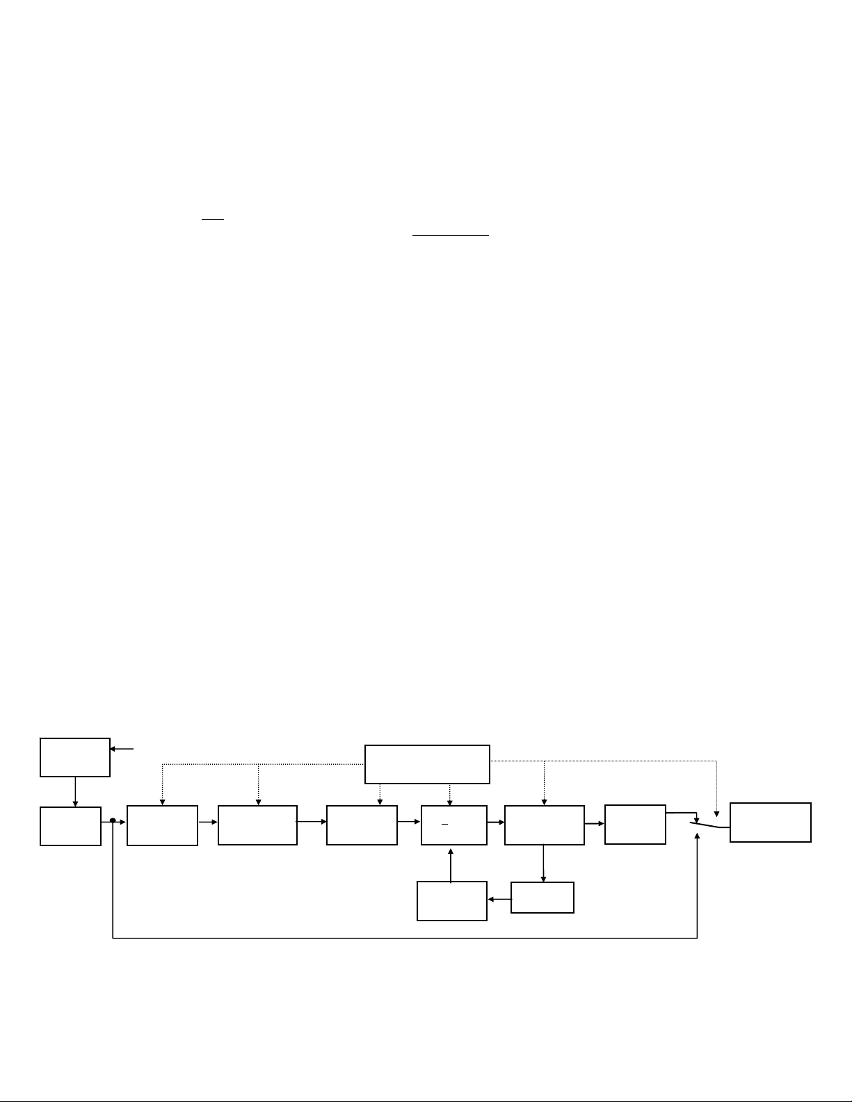
Refer to the simplified block diagram, Figure 1, for system description. An AC source is fed through a
double pole breaker for both Hot and Neutral protection. This breaker then feeds the power circuits and
all internal microelectronics. Input voltage is monitored to allow for continuous operation over a -25% to
+35% range of nominal voltage for all load conditions. An input voltage variation outside the preset
window will transfer operation to battery energy without a shutdown.
The input AC, when within the specified window, is power factor corrected and then sent to the
rectification stage. The DC rectifier stage provides both positive and negative voltages to a DC rail stage,
which then feeds the digitally controlled inverter AC. The AC inverter supplies the load and supports the
battery charger as long as input utility is available. Normally the output inverter is at 60Hz independent of
the input line frequency. The output inverter is synchronized to the utility line frequency.
circumstance for the most complete and reliable service to the critical load. This
applications.
During a utility power-loss, the AC rectification and battery charging capabilities of the UPS become
inactive. The fully charged battery system now becomes the source of power feeding the AC Inverter
generator. All systems are controlled by the digital microprocessor at all times.
The CMN Series on-line topology is unique to other on-line systems in that it is designed to meet the
needs of all non-linear type loads while providing input power factor correction. Computers and
telecommunications equipment, with their switching power supplies are considered a non-linear load,
which can be very abusive to most power protection equipment and could decrease life expectancy. The
CMN Series is specially designed with a power factor corrected input to eliminate harmonics back into
the power source as well as accept non-linear loads and protect them efficiently without any output
waveform degradation common to other UPS designs.
If the unit is overloaded, it will shutdown completely if the overload is not corrected within 3 seconds.
INPUT
ISOLATION
TRANSFORMER
UTILITY INPUT
MICROPROCESSOR
CONTROLLER
EMERGENCY
RFI
INPUT
FILTER
VOLTAGE
WINDOW
DETECTOR
POWER
FACTOR
CORRECTOR
RECTIFIER
+ DC
RAILS
AC
INVERTER
GENERATOR
COMMON
MODE
CHOKE
STANDBY
BATTERY
CHARGER
BYPASS LINE
CUTOFF
SWITCH
COMPUTER
(LOAD)
FIGURE 1: CMN SERIES BLOCK DIAGRAM
Page 4
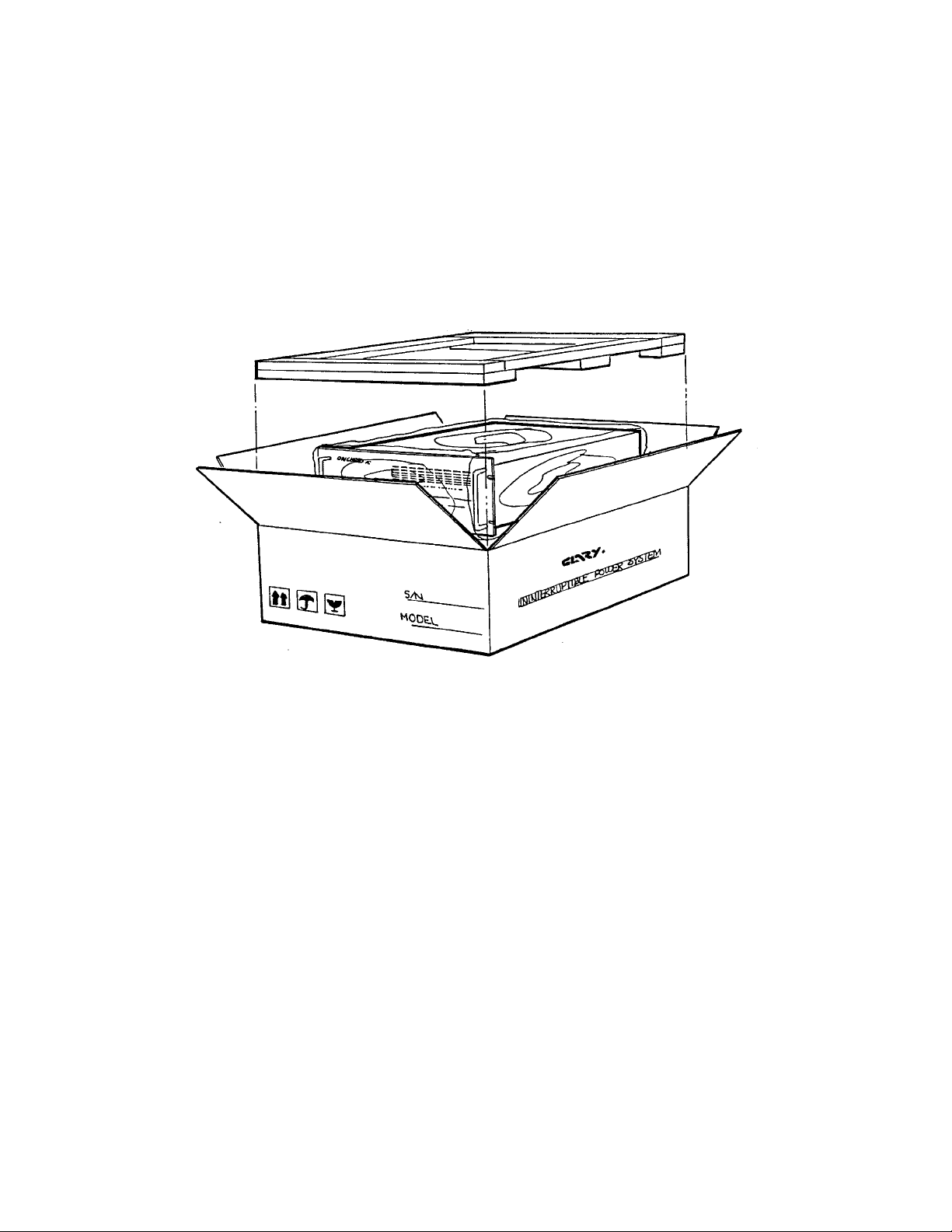
UNPACKING THE UNIT
Your UPS has been carefully packaged to withstand most abuse sustained during shipment. If there is
significant damage to the carton, or if there is any physical damage to this unit, report this to your carrier.
It is recommended to save the shipping container and packaging materials for future transporting, if
necessary. Transporting the unit in other than supplied shipping materials can result in unit damage not
covered by the manufacturer's warranty.
FIGURE 2: UNPACKING THE UNIT
Page 5
PHYSICAL DESCRIPTION
The following illustrations depict the basic Rackmount CMN Series unit. Reference the SUMMARY OF
INDICATORS AND CONTROLS Section for a further description of the call-outs.
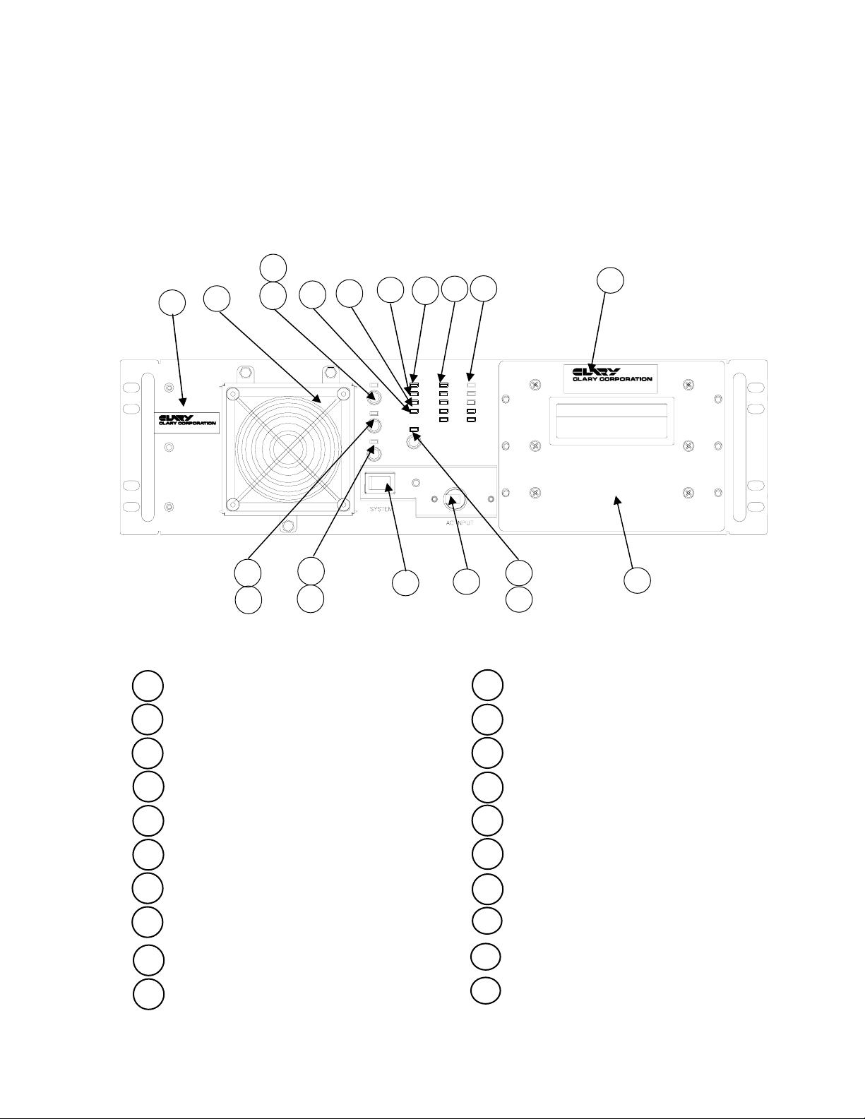
FIGURE 3: RACKMOUNT FRONT VIEW
20
18
11
12
3
6
7
8
4
5
19
FULL
LOW
LOAD
OVER
100%
75%
50%
25%
BATTERY PACK P/N 223-15176
CODE ___________ DATE / /
Model No. CMN2400D-PD
Model No. CMN2400D-PD
Part No. 100-15176
Part No. 100-15176
STATUS BATTERY
BYPASS
LOAD
ON/OFF
REPLACE
BATT
TEST
FAULT
ALARM
RESET
AC IN
AC O K
OUTPUT
ON BATT
COLD
START
13
14
15
16
2
1
9
10
17
1 AC INPUT POWER SWITCH 11 LOAD ON/OFF SWITCH
2 SYSTEM ON/OFF SWITCH 12 BYPASS LED
3 ON BATTERY LED 13 BATTERY TEST SWITCH
4 LOAD LEDs 14 REPLACE BATTERY LED
5 BATTERY LEVEL LEDs 15 ALARM RESET SWITCH
6 AC IN LED 16 FAULT LED
7 AC OK LED
8 AC OUTPUT LED
COLD START SWITCH
9
COLD START LED
10
BATTERY PACK-SLIDE OUT
17
18
FAN GUARD
BATTERY PACK
19
DATE CODE LABEL
20 UNIT IDENTIFICATION LABEL
Page 6
25
26
24
23
SNMP
CONTROL PANEL
RS232
INTERFACE
21
AC INPUT
22
27
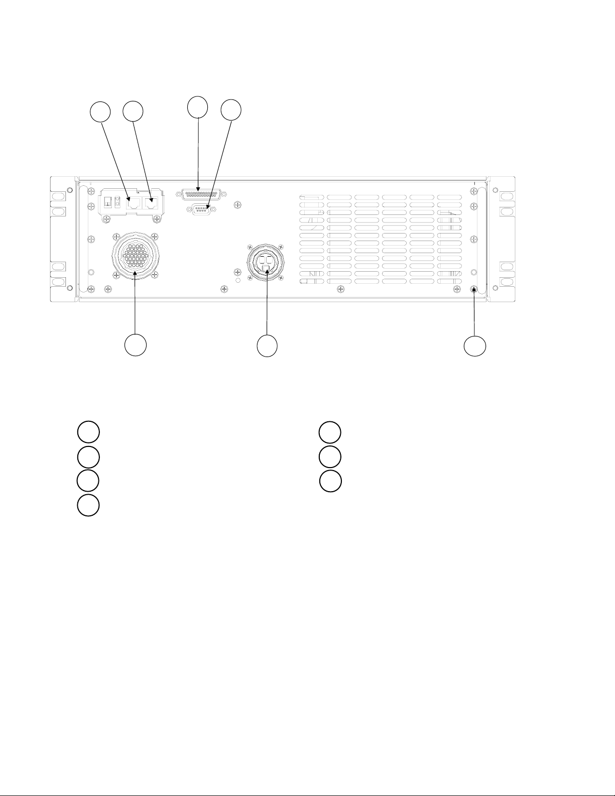
FIGURE 4: RACKMOUNT REAR VIEW
21 INTERFACE- CPC Type 37 Pin Connector 25 SNMP COM
22 INPUT - CPC Type Connector 26 SNMP LAN
23 RS232 CONNECTOR – DB9F 27 GROUND STUD
24 CONTROL PANEL CONNECTOR –
DB25F
Page 7
 Loading...