

Page 1
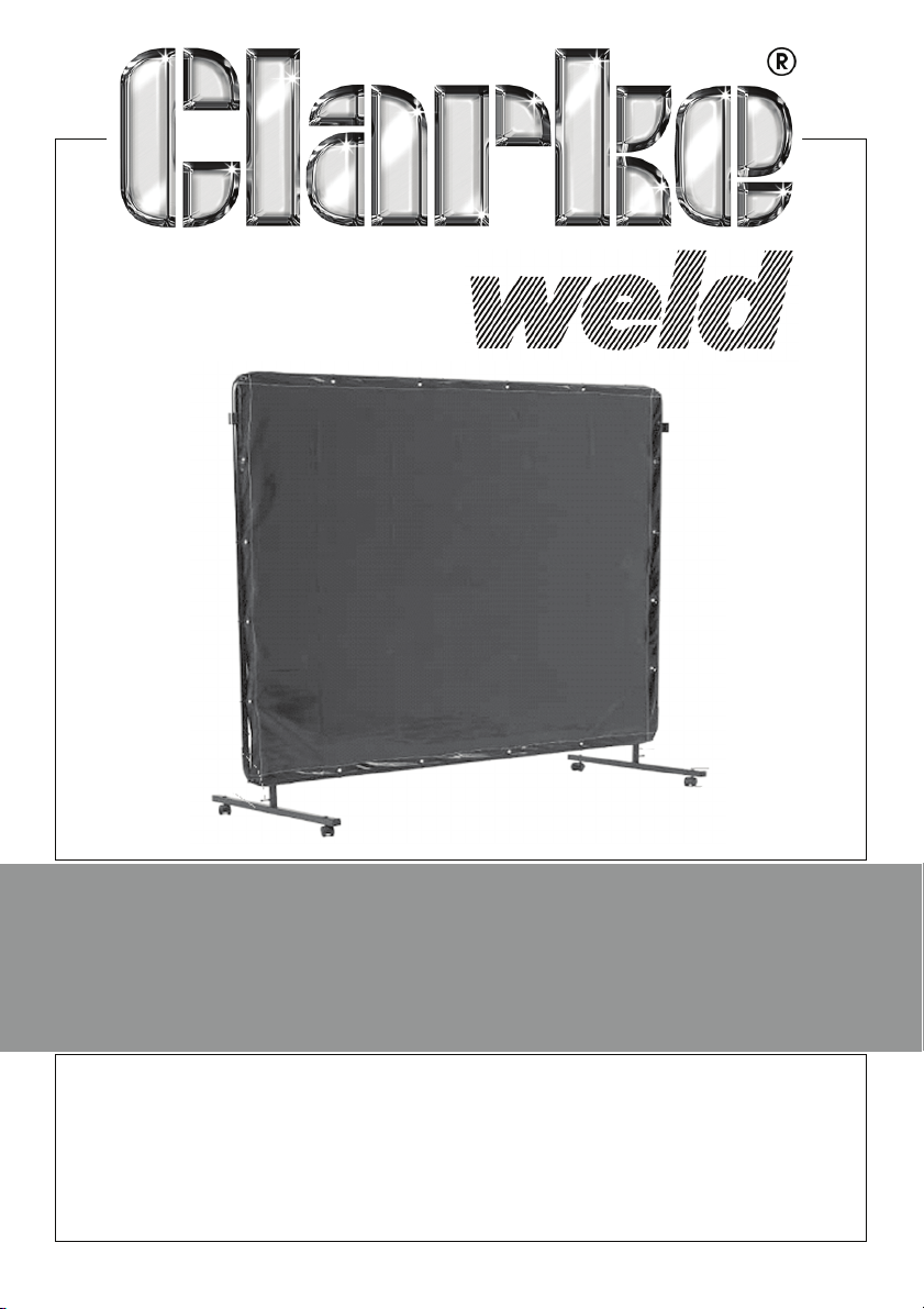
WELDING SCREEN FRAME
MODEL NO: WSC2
PART NO: 6000945
USER INSTRUCTIONS
ORIGINAL INSTRUCTIONS GC 0620 - ISS 4
Page 2

INTRODUCTION
Thank you for purchasing this CLARKE Welding Screen Frame.
Use this screen for face, eye and general protection against harmful rays,
sparks and splatter from welding and cutting.
Additional WSC2 screens can be added by using the connecting tubes
supplied.
Please follow the instructions given. In doing so you will ensure the safety of
yourself and that of others around you and you can look forward to the
product giving you long and satisfactory service.
GUARANTEE
This product is guaranteed against faulty manufacture for a period of 12
months from the date of purchase. Please keep your receipt which will be
required as proof of purchase.
This guarantee is invalid if the product is found to have been abused or
tampered with in any way, or not used for its intended purpose. Faulty goods
should be returned to their place of purchase, no product can be returned to
us without prior permission.
This guarantee does not effect your statutory rights.
ENVIRONMENTAL PROTECTION
Do not dispose of welding products with general household waste. They
contain valuable raw materials and should be disposed of appropriately at a
recognised disposal facility.
GENERAL SAFETY WARNINGS
1. DO NOT place so close to the welding operation that the screen is
constantly exposed to excess heat /sparks or allow the screen to come into
contact with hot surfaces. DO NOT use if the screen is torn or split.
2. When welding indoors ensure there is adequate ventilation.
3. NEVER look at an electric arc without protection. A welding headshield or
helmet with appropriate lenses must be used when welding. All persons
present must always use a proper welding face shield with suitable lenses.
4. After welding, always check that the area is free of any sparks or glowing
embers.
5. When necessary, use identical replacement parts to ensure that the safety
of the product is maintained.
2
Parts & Service: 020 8988 7400 / E-mail: [email protected] or [email protected]
Page 3
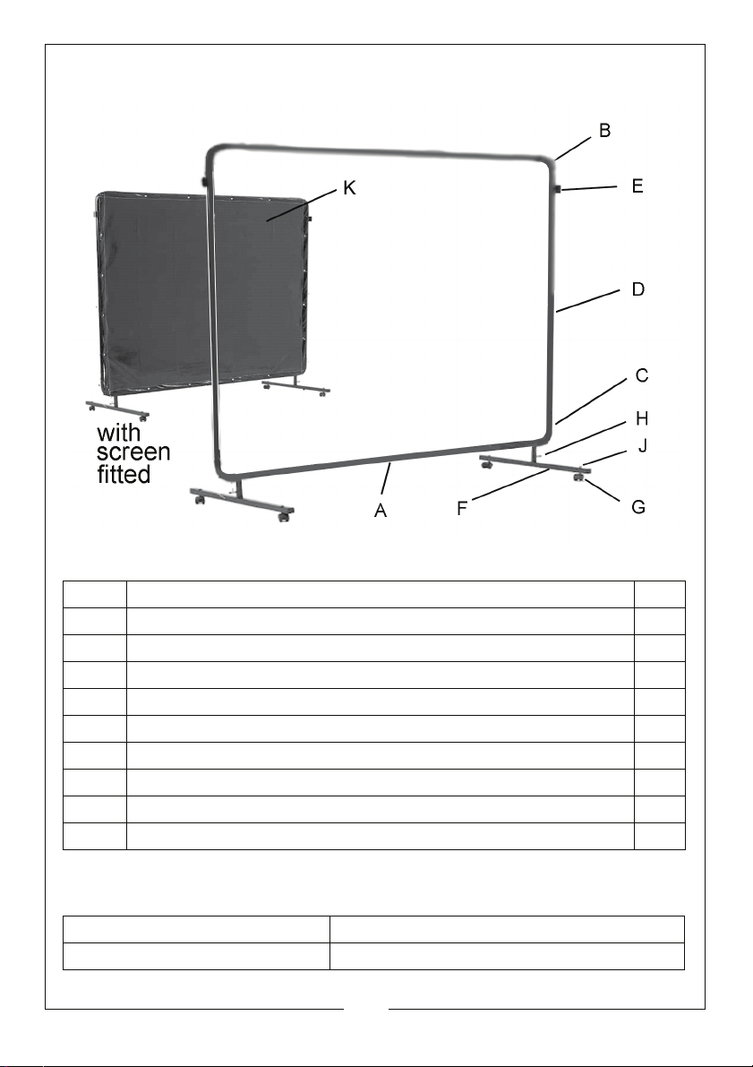
COMPONENT PARTS
A Top/bottom tubes 2
BTop corner tubes 2
C Bottom corner tubes 2
DSide tubes 2
E Welding screen connecting tubes 2
F Base supports 2
G Castors (2 with parking brakes) 4
H Wingnuts 2
J Castor domed nuts 4
K Welding screen 1
SPECIFICATIONS
Weight 5.35 kg
Dimensions (D x L x H) 660 x 1795 x 1965 mm
3
Parts & Service: 020 8988 7400 / E-mail: [email protected] or [email protected]
Page 4

ASSEMBLY
1. Connect the top/bottom tubes (A) to the corner tubes (B & C), noting that
the limb of (C) must point downwards.
• The spring-loaded pins on the tubes will spring into place for security.
2. If required, for creating a fence of screens, slide the welding screen
connecting tubes (E) onto the side tubes (D) until they rest against the
lower of the two spring loaded pins.
3. Join the side tubes (D) to the corner tubes (B & C) to complete the frame.
4. Connect the bottom corner tubes (C) to the base supports (F) and secure
by tightening the wingnuts (H).
5. Fit the castors (G) to the base supports, securing them with the domed nuts
(J). Lock in position using a 13mm wrench on the caster locknut and a
14mm wrench on the dome nut.
6. Attach the welding screen (K) to the frame using the cable ties supplied.
7. Take care to attach all the cable ties from the same side and initially
connect loosely before tightening them equally all around the screen.
8. The welding screen may be prevented from moving by applying the
brakes on one pair of casters. Press down with your foot on the brake levers
to apply the brakes. Lift the lever up to release
4
Parts & Service: 020 8988 7400 / E-mail: [email protected] or [email protected]
 Loading...