

Page 1
WARNING: Do not use the machine without reading this manual
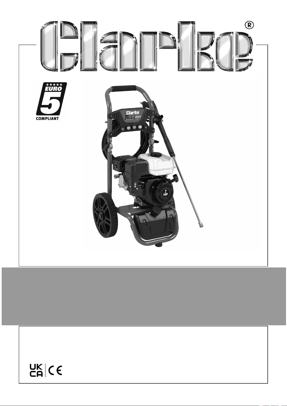
PETROL DRIVEN POWER WASHER
MODEL NO: TIGER 3200
PART NO: 7320213
OPERATION & MAINTENANCE
INSTRUCTIONS
ORIGINAL INSTRUCTIONS DL0525
Page 2
INTRODUCTION
Thank you for purchasing this CLARKE Petrol Pressure Washer.
Before attempting to use this product, please read this manual thoroughly and follow
the instructions carefully. In doing so you will ensure the safety of yourself and that of
others around you, and you can look forward to your purchase giving you long and
satisfactory service.
GUARANTEE
This product is guaranteed against faulty manufacture for a period of 12 months from
the date of purchase. Please keep your receipt which will be required as proof of
purchase.
This guarantee is invalid if the product is found to have been abused or tampered
with in any way, or not used for the purpose for which it was intended.
Faulty goods should be returned to their place of purchase, no product can be
returned to us without prior permission.
This guarantee does not effect your statutory rights.
ENVIRONMENTAL RECYCLING POLICY
One of the most damaging sources of environmental pollution is oil products. Never
throw away used oil with domestic refuse or flush it down a sink or drain. Collect any
oil in a leak proof container and take it to your local waste disposal site.
Should any components become completely unserviceable and require disposal,
plastic and metal components should be disposed for re-cycling according to local
regulations.
2
Parts & Service: 020 8988 7400 / E-mail: [email protected] or [email protected]
Page 3
GENERAL SAFETY RULES
WARNING: WATER AT HIGH PRESSURE CAN BE DANGEROUS AND
CAN CAUSE DAMAGE TO PERSONS OR PROPERTY IF THE OPERATOR
IS CARELESS. NEVER ALLOW ANYONE TO OPERATE THIS
EQUIPMENT UNLESS THEY ARE THOROUGHLY RELIABLE, AND
FAMILIAR WITH THE SAFETY PRECAUTIONS.
1. DO NOT point the spray at other people, animals, electrical equipment or the
machine itself.
2. DO NOT hold your finger over the high pressure nozzle.
3. DO NOT let children or untrained personnel use this machine.
4. DO NOT operate the machine with any of the covers removed.
5. DO NOT try to repair this machine. ALWAYS refer to your CLARKE service
department for all repairs.
6. DO NOT supply any liquid other than water to the water inlet.
7. DO NOT use the detergent pickup facility to introduce flammable liquids/solvents,
e.g. paint thinners, petrol, oil as there is a risk of explosion.
8. ALWAYS release the remaining pressure in the system; turn off the water supply
and operate the trigger before you remove hoses or accessories.
9. ALWAYS keep the machine dry and away from the water spray.
10. ALWAYS use protective clothing and safety glasses. Loose particles and other
items can be propelled at high speed by the water spray.
11. ALWAYS hold the gun securely & expect it to ‘kick’ when you pull the trigger.
12. ALWAYS respect the requirements of the local water company. Pressure washers
may only be connected to the mains water supply if a system separator (also
known as a back-flow preventer) is installed in the supply hose.
13. ALWAYS disconnect from the water supply, and make sure that you drain the
system when not in use. KEEP in a cool dry location.
14. ONLY use detergents that are suitable for pressure washers, see page 39 for a full
range of CLARKE pressure washer detergents (available from your CLARKE dealer).
15. WARNING High pressure water jets can be dangerous, the jet must not be
directed at a person or anything that they are wearing.
16. WARNING High pressure hoses, fittings and couplings are important for the
safety of the machine. Use only hoses, fittings and couplings recommended by the
manufacturer.
17. WARNING Water that passes through a system separator (also known as a
back-flow preventer) is not safe to drink.
18. DO NOT use the pressure washer if there is damage to the inlet/outlet hose or the
machine.
19. Place the pressure washer in a well ventilated area. This will allow for removal of
deadly exhaust gas. DO NOT place the pressure washer where the gas could
3
Parts & Service: 020 8988 7400 / E-mail: [email protected] or [email protected]
Page 4
accumulate and enter inside or be drawn into a potentially occupied building.
Ensure exhaust gas is kept away from any windows, doors, ventilation intakes, or
other openings that can allow exhaust gas to collect in a confined area. Prevailing
winds and air currents should be taken into account.
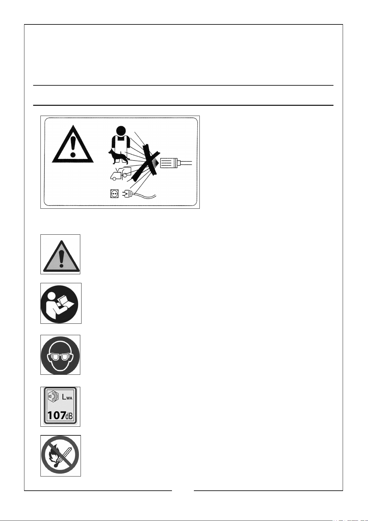
SAFETY SYMBOLS
WARNING: Risk of injection or
severe injury. DO NOT direct
discharge stream at persons or
animals. Keep clear of nozzle. This
machine is to be used only by
qualified operators.
WARNING: NEVER direct spray
toward any electrical device or
electrical outlet.
General Warning: Indicates that failing to follow these instruction
could result in injury or damage to the machine.
To reduce the risk of injury, read the manual before use.
ALWAYS wear safety glasses when using this machine.
WARNING: Load Noise, ALWAYS wear ear protection when using this
machine.
WARNING: No open flame, open ignition source and smoking is
prohibited.
4
Parts & Service: 020 8988 7400 / E-mail: [email protected] or [email protected]
Page 5
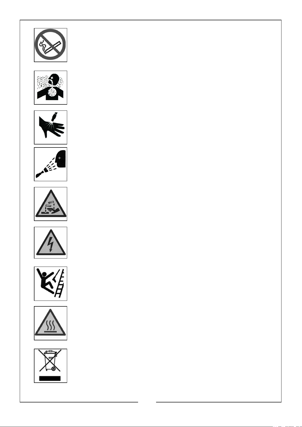
WARNING: No smoking
DANGER: R is k to b re at hing. Engin e ex ha us t fumes can kill.
For outdoor use only. Work in a well ventilated area.
WARNING: Risk of injection or severe injury. Do not direct
discharge stream at persons or animals. Keep clear of nozzle. This
machine is to be used only by qualified operators.
WARNING: Risk of spray injury. Spray can propel objects. Always
wear BS EN166 approved safety glasses or googles.
WARNING: Risk of chemical burn. Never spray acids, corrosive or
toxic chemicals. Use only cleaners formulated for pressure washers.
WARNING: Risk of electrocution. Never direct spray toward any
electrical device or electrical outlet.
WARNING: R is k o f u n sa fe op er a ti on . K ee p children away
from this equipment. Gun kicks back. Hold with both hands.
WARNING: Risk of hot surfaces.
Recycle unwanted materials instead of disposing of them as waste. All
tools, accessories and packaging should be sorted, taken to a recycling
centre and disposed of in a manner which is compatible with the
environment.
5
Parts & Service: 020 8988 7400 / E-mail: [email protected] or [email protected]
Page 6
Page 7
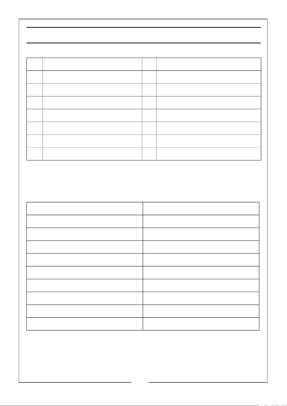
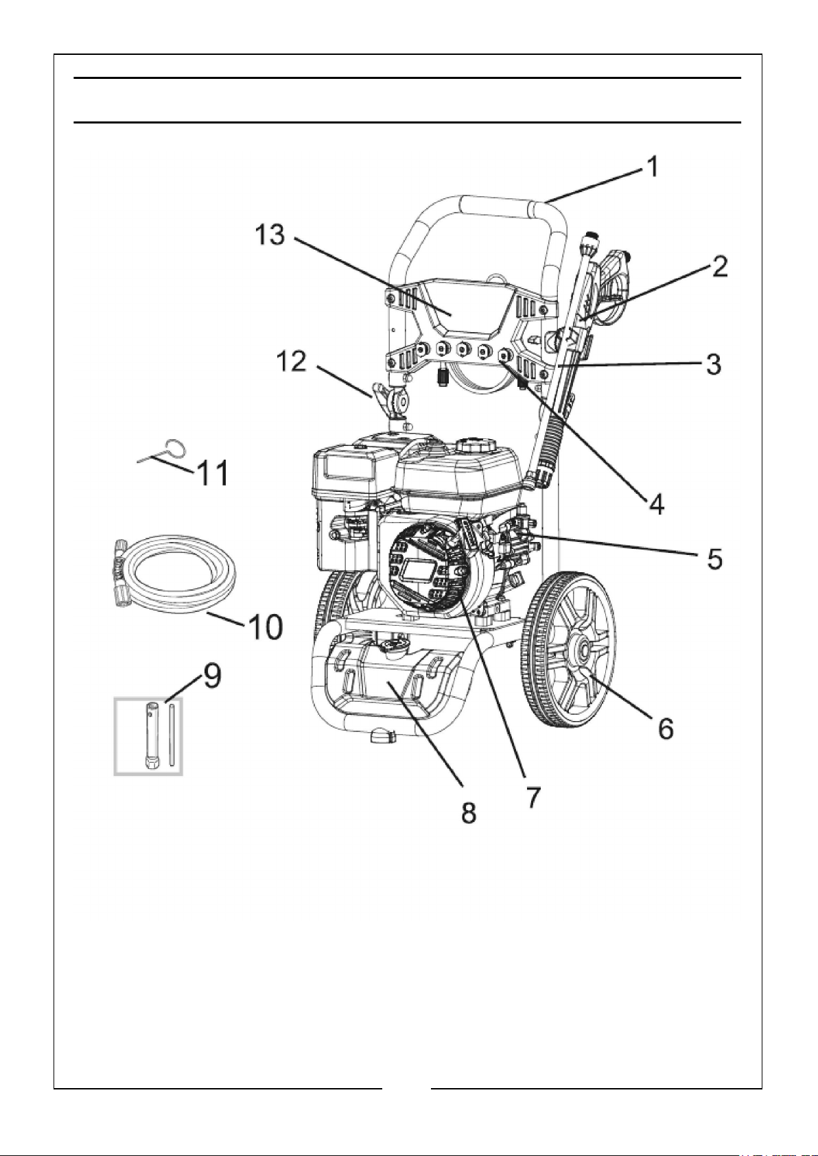
OVERVIEW DECRIPTIONS
NO DESCRIPTION NO DESCRIPTION
1 Frame 8 Detergent Tank
2 Spray Gun 9 Spark Plug Spanner
3 Spray Lance 10 High Pressure Outlet Hose
4 Nozzle x 5 11 Nozzle Cleaning Tool
5 Pressure Pump 12 Handle Adjustment Knob
6 Wheel x 2 13 Nozzle Panel
7 7hp Engine
UNPACKING
Unpack your pressure washer and check to ensure the following items are present.
Contact your CLARKE dealer immediately if any parts are missing or damaged.
1 x Petrol Pressure Washer 1 x Dual Head Screwdriver
2 x Wheels 1 x Spark Plug Box Spanner
2 x Wheel Axle Rod and Washer 1 x Nozzle Cleaning Tool
2 x ‘R’ Clips 1 x Spray Gun Holder
1 x Spray Gun 1 x Hose Hook
1 x Spray Lance 1 x Engine Manual
1 x High Pressure Hose (Outlet): Black 1 x Oil Funnel
1 x Water Supply Hose (Inlet): Blue 1 x Inlet Connector
1 x High Pressure Hose Connector 1 x Hose Clip
5 x Gun Nozzles
7
Parts & Service: 020 8988 7400 / E-mail: [email protected] or [email protected]
Page 8
ASSEMBLY
Your pressure washer requires some assembly before it is ready for use. You will require
the following tools:
• Open Ended Spanners: 8mm and 10 mm
UNPACKING
WARNING: PRESSURE WASHER IS HEAVY. DO NOT ATTEMPT TO
LIFT AND REMOVE THE PRESSURE WASHER UNIT FROM THE
CARTON WITHOUT ASSISTANCE FROM ANOTHER PERSON OR
UNPACK AS INSTRUCTED BELOW.
1. Set the carton on a rigid, flat surface. Remove all loose parts and packing.
2. Leave pressure washer in the carton.
3. Using a box cutter, open the carton completely by cutting the four corners
allowing the sides to lay flat.
4. Leave the pressure washer on the carton while you install the wheels and rubber
feet.
FITTING THE WHEELS
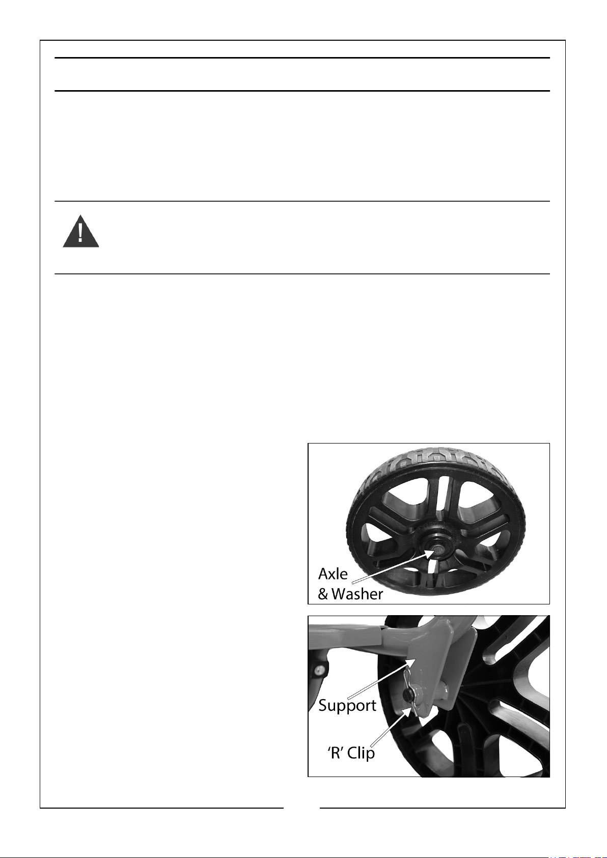
1. On each wheel, slide the axle rod and
washer through the centre hole in the
wheel, as shown.
2. Slide each axle rod through the axle
supports on the bottom of the frame
and secure each wheel with the
supplied ‘R’ clip.
8
Parts & Service: 020 8988 7400 / E-mail: [email protected] or [email protected]
Page 9
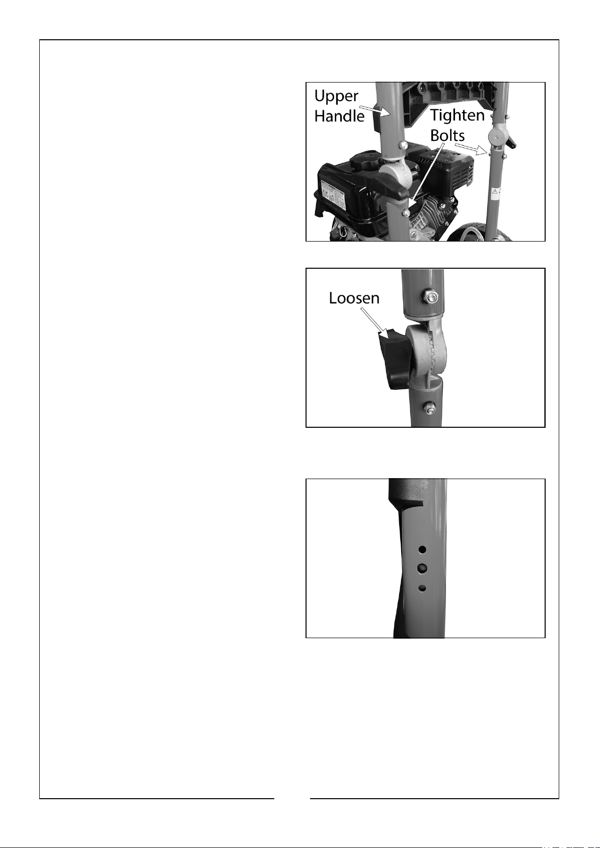
FITTING THE HANDLE
1. Slide the upper handle onto the
frame struts.
2. Secure in place with the nut, bolt and
washers supplied, using 8mm and
10mm open ended spanners.
3. The angle of the upper handle can be
adjusted by loosening the two knobs
on the sides and moving the handle
to the required angle, and then retightening the knobs.
FITTING THE SPRAY GUN HOLDER
1. On the side of the upper handle are 3
holes for securing the holder as
shown.
9
Parts & Service: 020 8988 7400 / E-mail: [email protected] or [email protected]
Page 10
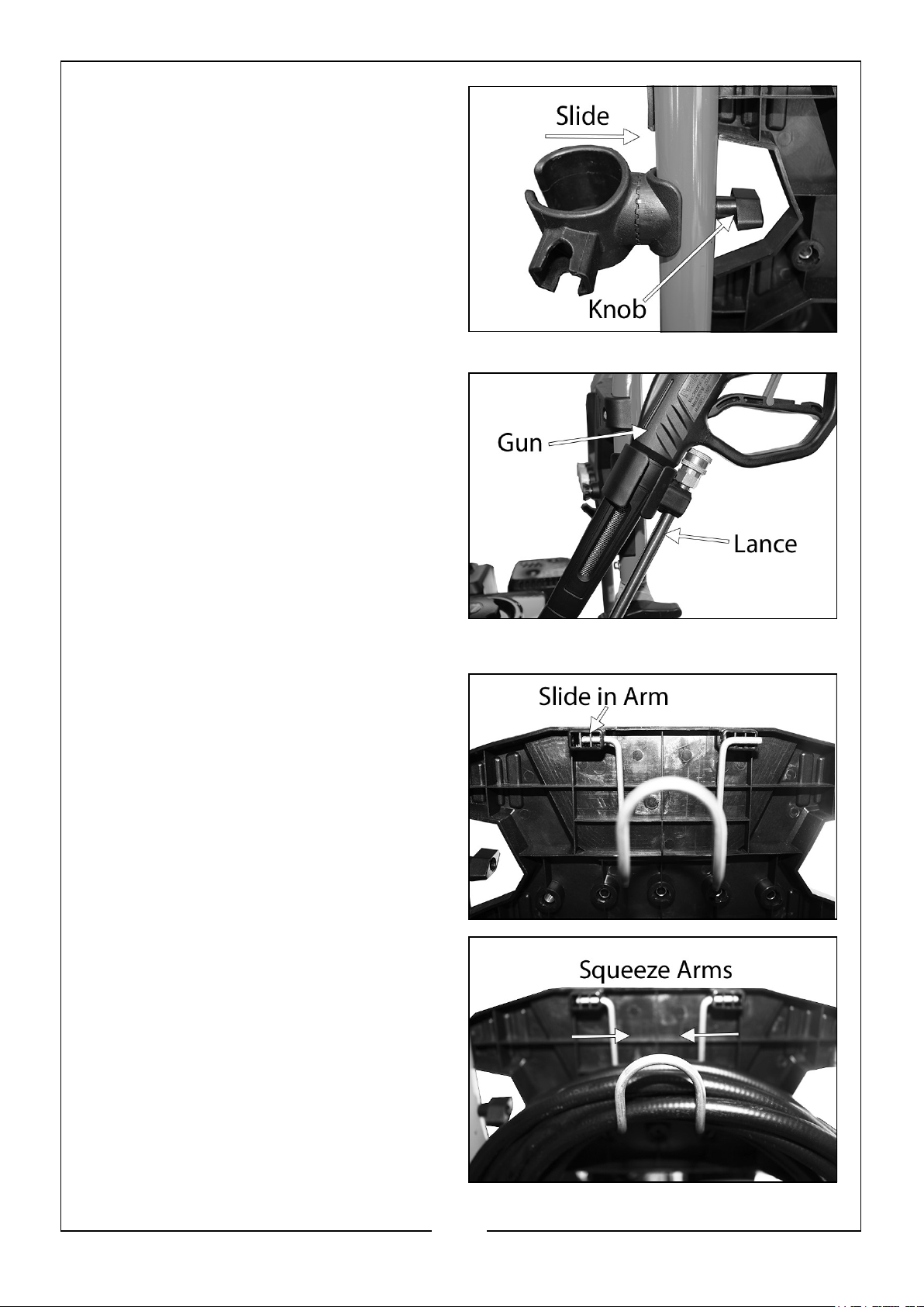
2. Place the holder over the 3 holes and
slide the bolt through the middle hole
and secure on the other side of the
handle with the knob.
3. To store the spray gun, separate the
lance from the gun and place in the
holder as shown.
FITTING THE HOSE SUPPORT
1. On the backside of the nozzle panel,
place one arm of the hose hook into
the slot at the top, as shown.
2. Squeeze the two arms of the hook
together so the other arm can slide
into the opposite slot, as shown.
10
Parts & Service: 020 8988 7400 / E-mail: [email protected] or [email protected]
Page 11
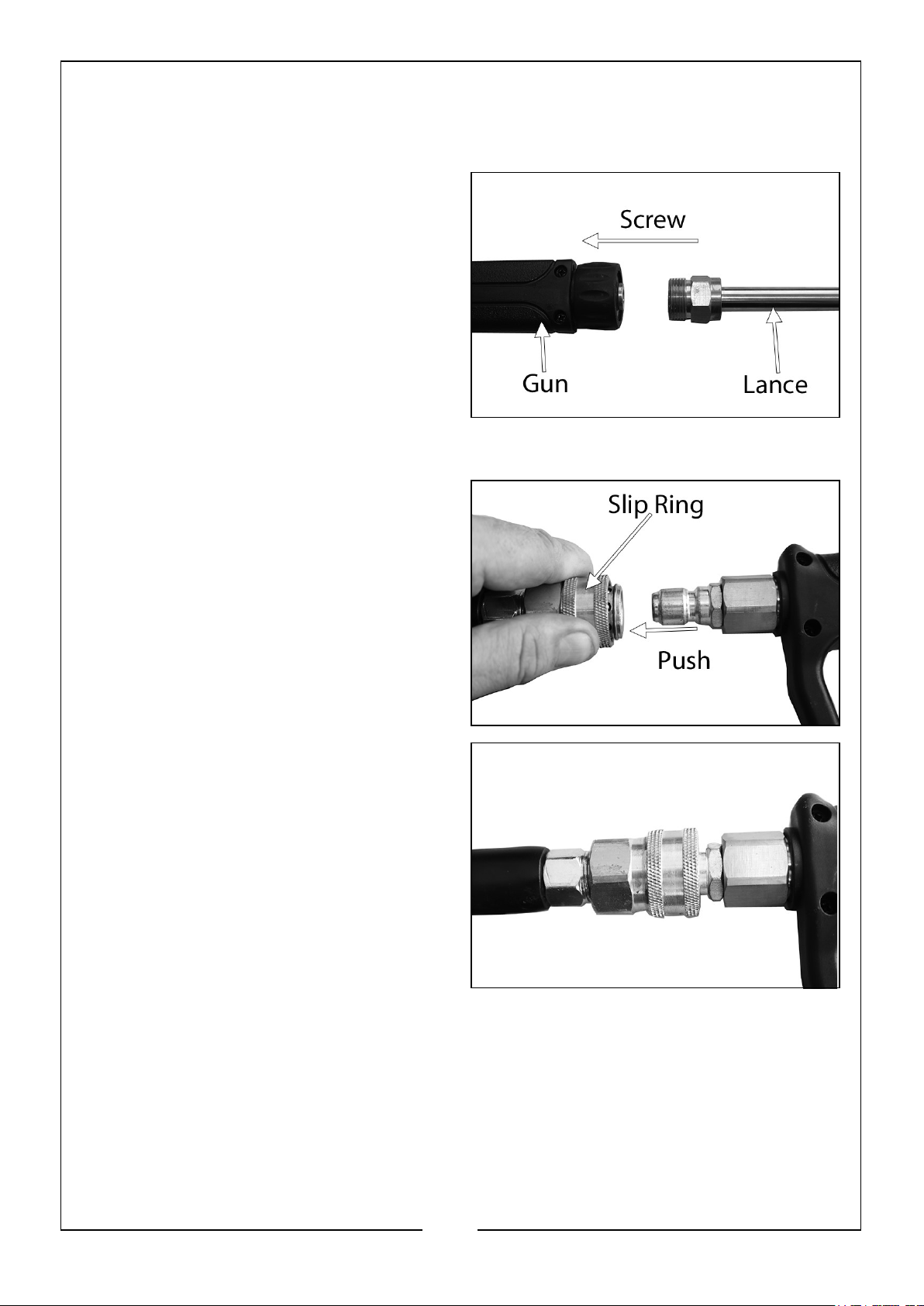
CONNECTING THE GUN, LANCE & HIGH PRESSURE HOSE
CONNECTING THE GUN AND LANCE
1. Screw the lance into the end of the
gun as shown.
CONNECT THE HOSE TO THE GUN
1. Pull back the slip ring on the female
quick release fitting of the high
pressure hose.
2. Push the male quick release fitting on
the gun handle into the female quick
release on the hose.
3. Release the slip ring and make sure
the connection is tight.
11
Parts & Service: 020 8988 7400 / E-mail: [email protected] or [email protected]
Page 12
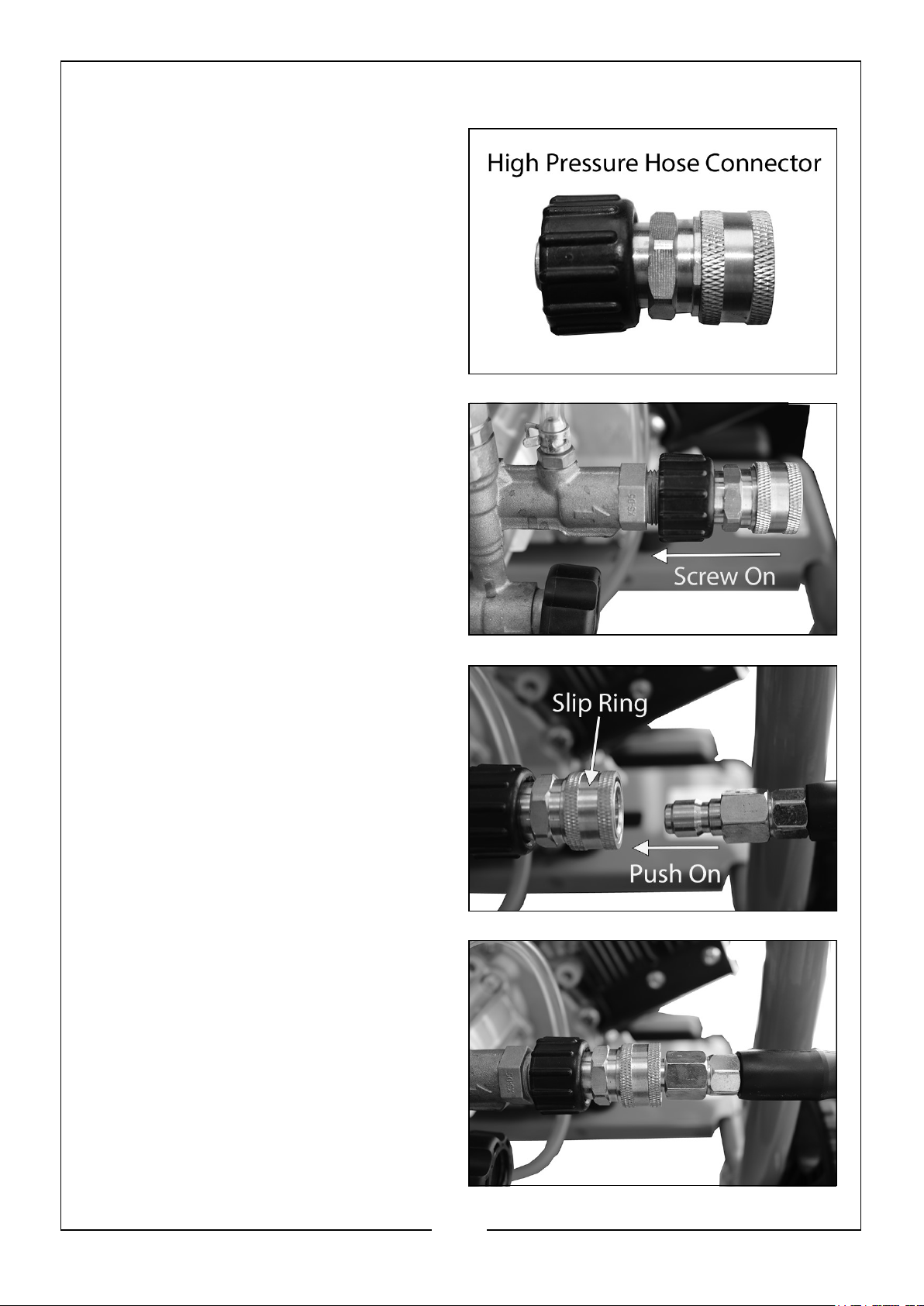
CONNECT THE HOSE TO THE PRESSURE WASHER
1. Screw the hose connector on to the
pressure washer, as shown.
• Tighten the connector, hand tight
only, DO NOT use a spanner.
NOTE: Make sure the connection is
secure.
2. Pull back the slip ring on the female
quick release fitting of the connector.
3. Push the male quick release fitting on
the hose into the female quick
release on the connector.
4. Release the slip ring and make sure
the connection is tight.
12
Parts & Service: 020 8988 7400 / E-mail: [email protected] or [email protected]
Page 13
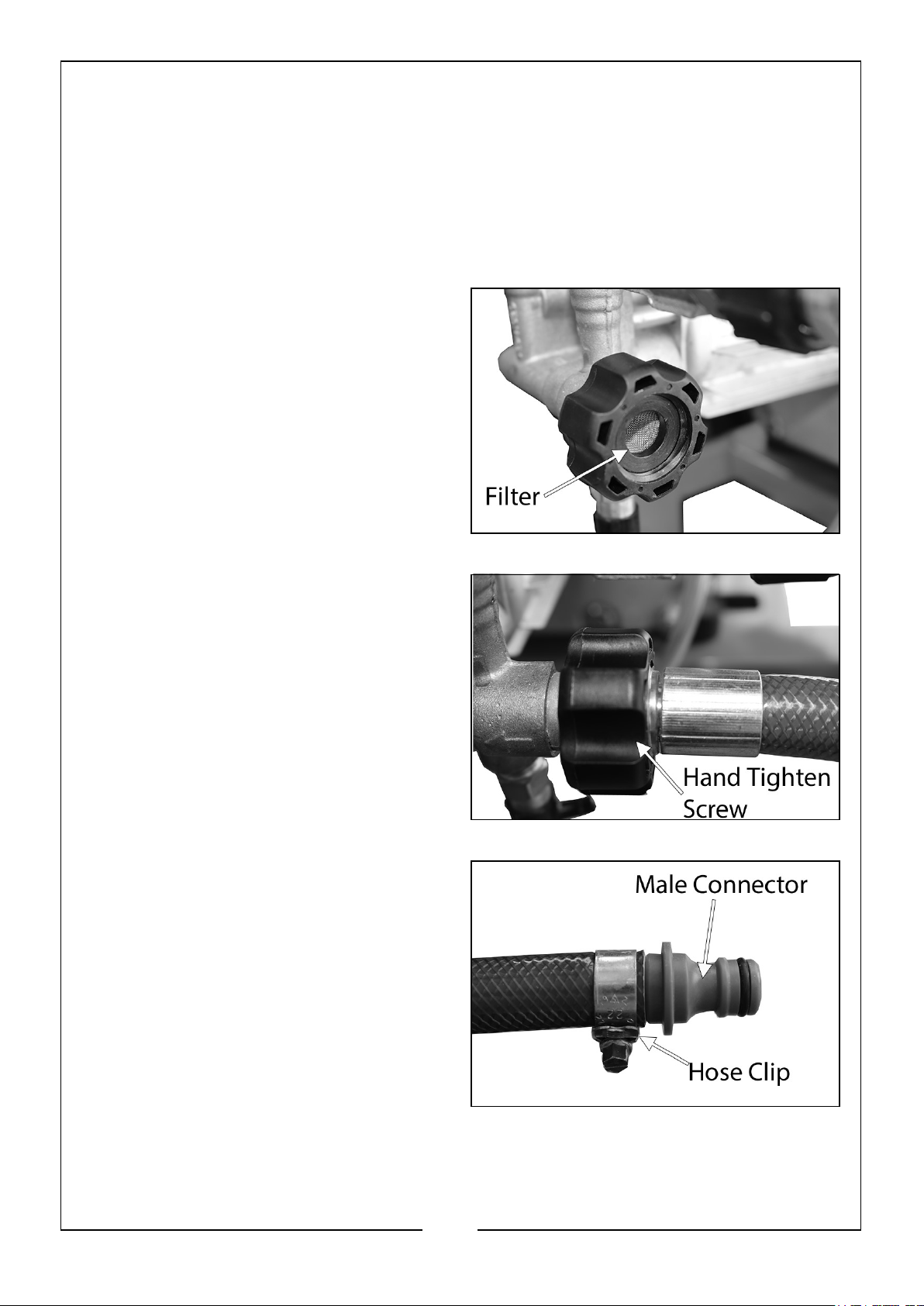
CONNECTING THE WATER SUPPLY
Always follow the regulations of your local water supplier. The pressure washer must
never be connected to the drinking water supply without using a system separator
(also known as a backflow preventer) available from most hardware, plumbing or
garden stores.
NOTE: Water that has flowed through a system separator is considered non-
drinkable.
1. Make sure the water inlet has the
water filter inserted before attaching
the hose.
NOTE: DO NOT use if there is no water
filter or the filter is damaged.
2. Connect the water supply hose to the
water inlet by pushing the hose end
that has the threaded connector into
the water inlet and tightening the
black screw.
• Tighten the screw, hand tight only,
DO NOT use a spanner
NOTE: Make sure the connection is
secure.
3. Insert a male hosepipe connector
(not supplied) into the other end of
the water supply hose and secure
using the hose clip supplied.
4. Connect the male hosepipe connector
to a female hosepipe connector (not
supplied) that is connected to a water
source.
13
Parts & Service: 020 8988 7400 / E-mail: [email protected] or [email protected]
Page 14
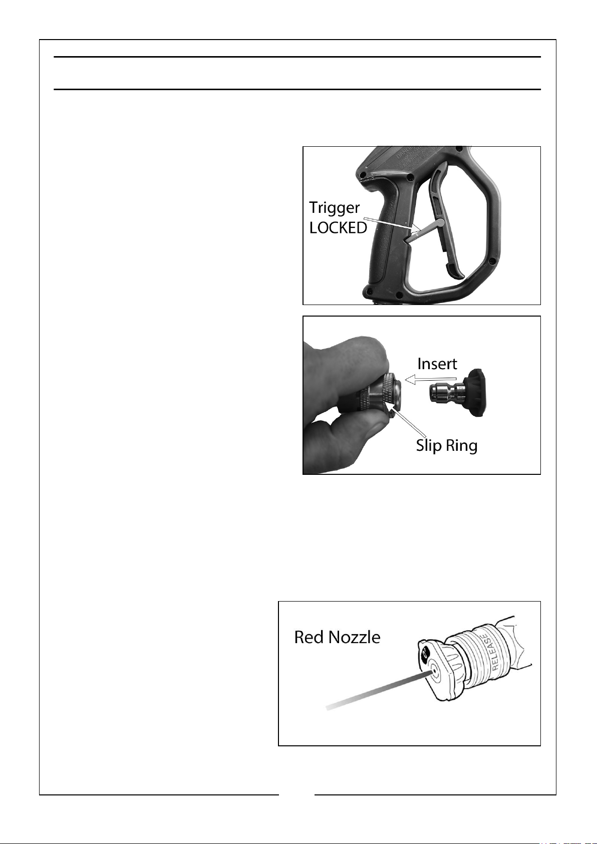
USING THE CORRECT NOZZLE
ATTACHING/CHANGING PRESSURE NOZZLES TO SPRAY LANCE
1. ALWAYS make sure the safety latch
on the gun trigger is in the ‘LOCKED’
position before changing a nozzle.
2. Pull back the slip ring on the female
quick release fitting of the spray
lance.
3. Insert the male quick release fitting
on the pressure nozzle into the
female quick release on the spray
lance.
4. Release the slip ring and twist. Listen
for a click to ensure both quick
release sections are coupled.
5. To remove a nozzle, repeat steps 1 - 4 in reverse order.
NOZZLE TYPES
The pressure washer comes with five spray nozzles. Each nozzle is colour coded and
delivers a specific spray pattern and pressure for a particular cleaning job. The size of
the nozzle determines the size of the fan spray and the pressure out of the nozzle.
0o NOZZLE - RED
This nozzle delivers a pinpoint
stream of pressurised water and is
extremely powerful. It covers only a
small area of cleaning. This nozzle
should only be directed at surfaces
that can withstand high pressure
such as metal or concrete. DO NOT
use this nozzle to clean wood.
14
Parts & Service: 020 8988 7400 / E-mail: [email protected] or [email protected]
Page 15
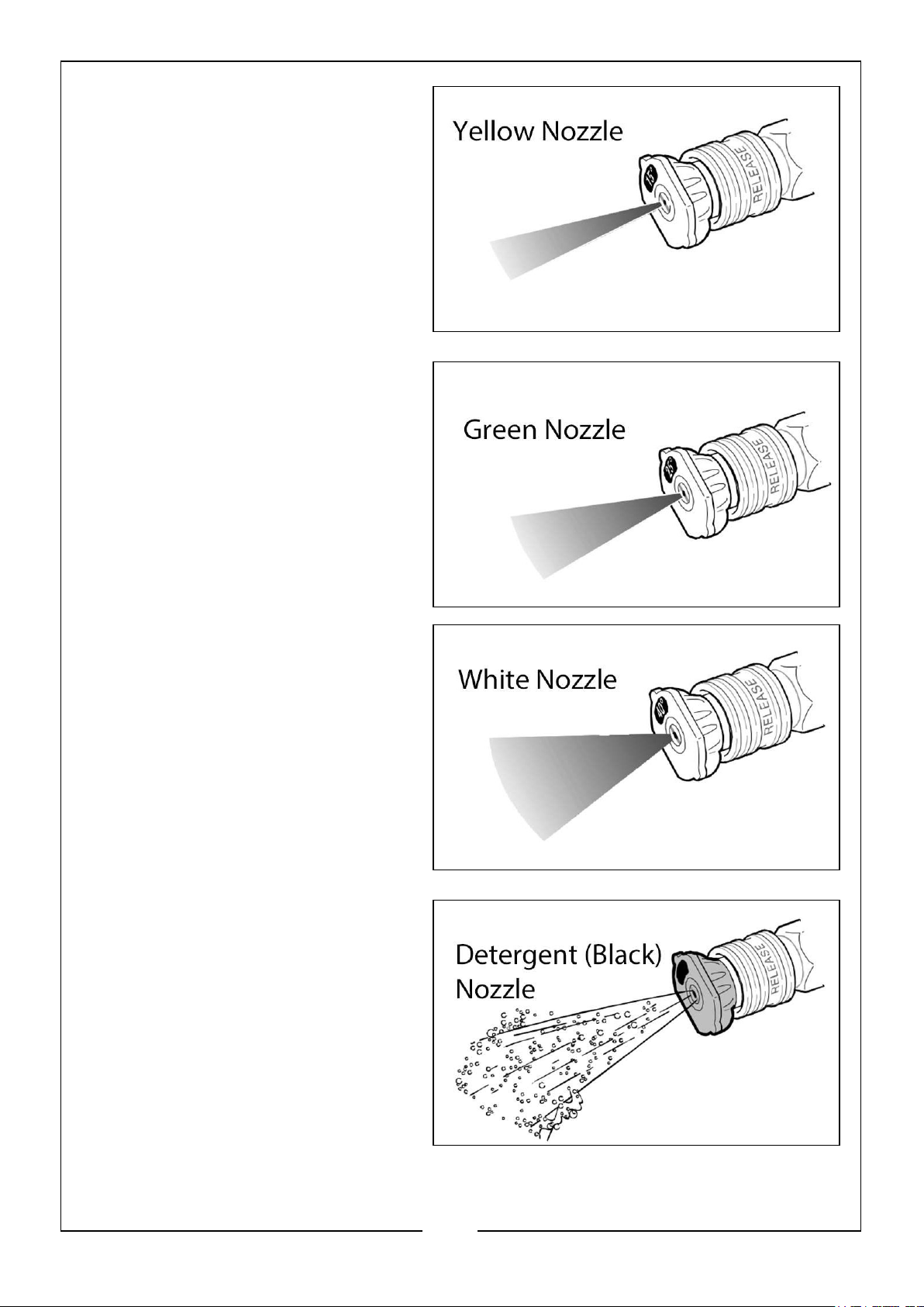
15o NOZZLE - YELLOW
This nozzle delivers a powerful 15o
spray pattern for intense cleaning of
small areas. This nozzle should only
be used on areas and materials that
can withstand high pressure.
25o NOZZLE - GREEN
This nozzle delivers a 25o spray
pattern for intense cleaning of larger
areas. This nozzle should only be
used on areas and materials that
can withstand pressure from this
nozzle.
40o NOZZLE - WHITE
This nozzle delivers a 40o spray
pattern and a less powerful stream
of water. This nozzle can cover a
wide area and should be used for
most general cleaning jobs.
DETERGENT NOZZLE - BLACK
This nozzle is used to apply special
detergents and cleaning solutions.
This nozzle produces the weakest
pressure stream of the five nozzles.
15
Parts & Service: 020 8988 7400 / E-mail: [email protected] or [email protected]
Page 16
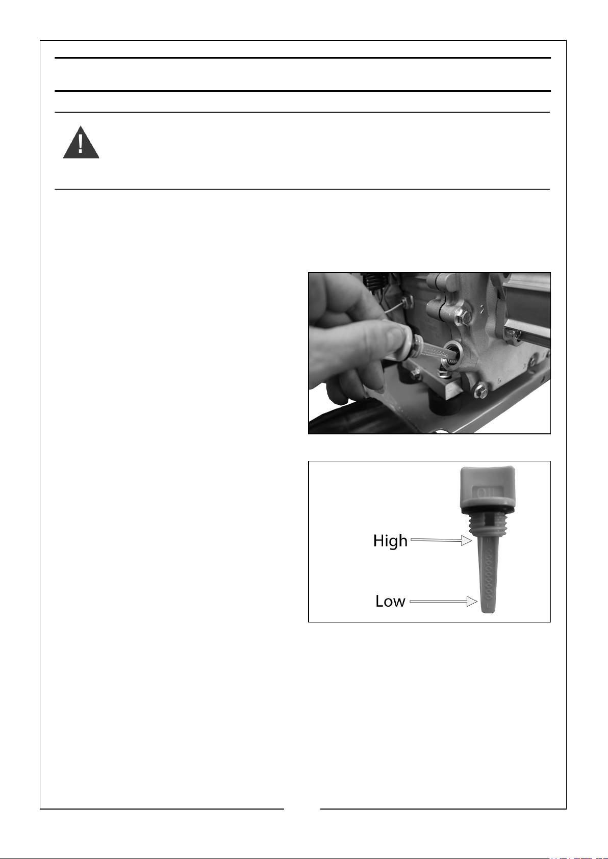
BEFORE USE
WARNING: STAND THE PRESSURE WASHER ON LEVEL GROUND
WITH THE ENGINE SWITCHED OFF.
WARNING: THE OIL LEVEL SHOULD ONLY BE CHECKED WITH A
COLD ENGINE. A HOT ENGINE WILL GIVE A FALSE READING.
IMPORTANT: The engine is supplied without any oil in it and must be
filled to the correct level before starting for the first time, see below.
ENGINE OIL
1. Turn the oil filler cap anticlockwise
and remove it from the engine, wipe
the integral dipstick with a clean
cloth.
2. Insert the oil filler cap back into place
and then remove it again.
3. If the oil reads low on the dipstick,
using the oil funnel add oil to the oil
reservoir (Max 0.6L).
• We recommend the use of
SAE10W-30 oil.
• DO NOT overfill the oil reservoir.
4. Replace the oil filler cap.
NOTE: Running the engine with insufficient oil will cause engine damage.
NOTE: LOW OIL SENSOR: To prevent engine damage caused by an insufficient
amount of oil in the crankcase, the engine is equipped with a low oil sensor. If
the oil is below the safe amount, the sensor will activate and will prevent the
engine start up or will stop the engine running. If the pressure washer shuts
off and the oil level is within specifications, check to see if the washer is
sitting at an angle. Place on an even surface to correct this. If the engine fails
to start, the oil level may not be sufficient to deactivate the sensor. Add oil as
described above.
16
Parts & Service: 020 8988 7400 / E-mail: [email protected] or [email protected]
Page 17
FUEL
WARNING: REFUEL IN A WELL-VENTILATED AREA, AWAY FROM ANY
SOURCES OF IGNITION.
WARNING: IF THE ENGINE HAS BEEN RUNNING, ALLOW IT TO COOL
BEFORE REFUELING.
WARNING: DO NOT LEAVE FUEL WITHIN THE REACH OF CHILDREN.
WARNING: REFUEL CAREFULLY TO AVOID SPILLING FUEL.
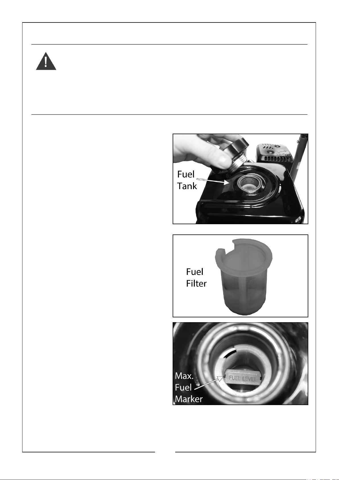
1. Remove the fuel tank cap.
• Just inside the fuel tank is a fuel
filter, which should be checked
periodically and any contaminants
which have accumulated must be
removed.
2. Pour unleaded petrol through the fuel
filter and into the fuel tank.
• DO NOT fill above the red fuel
filter marker.
• Use unleaded petrol with a pump
octane rating of 86 or higher.
3. Replace the fuel filler cap securely.
17
Parts & Service: 020 8988 7400 / E-mail: [email protected] or [email protected]
Page 18
STARTING YOUR PRESSURE WASHER.
WARNING: FAILURE TO TURN ON THE WATER COULD CAUSE
DAMAGE TO THE PRESSURE WASHER.
PRIOR TO STARTING PRESSURE WASHER
Make sure that you have done the following
1. Selected the correct nozzle for the job at hand, see pages 15-16
2. Attached the washer to a water source and turned the source on, see page 14
3. You are wearing the appropriate protective equipment and clothing.
4. The washer is outside in a fully ventilated area.
5. The washer is on a flat and level surface and close to the work area. Keep a
minimum of 5ft (1.5m) clearance on all sides of the engine including the top.
Make sure the exhaust is pointing away from any buildings.
STARTING THE PRESSURE WASHER
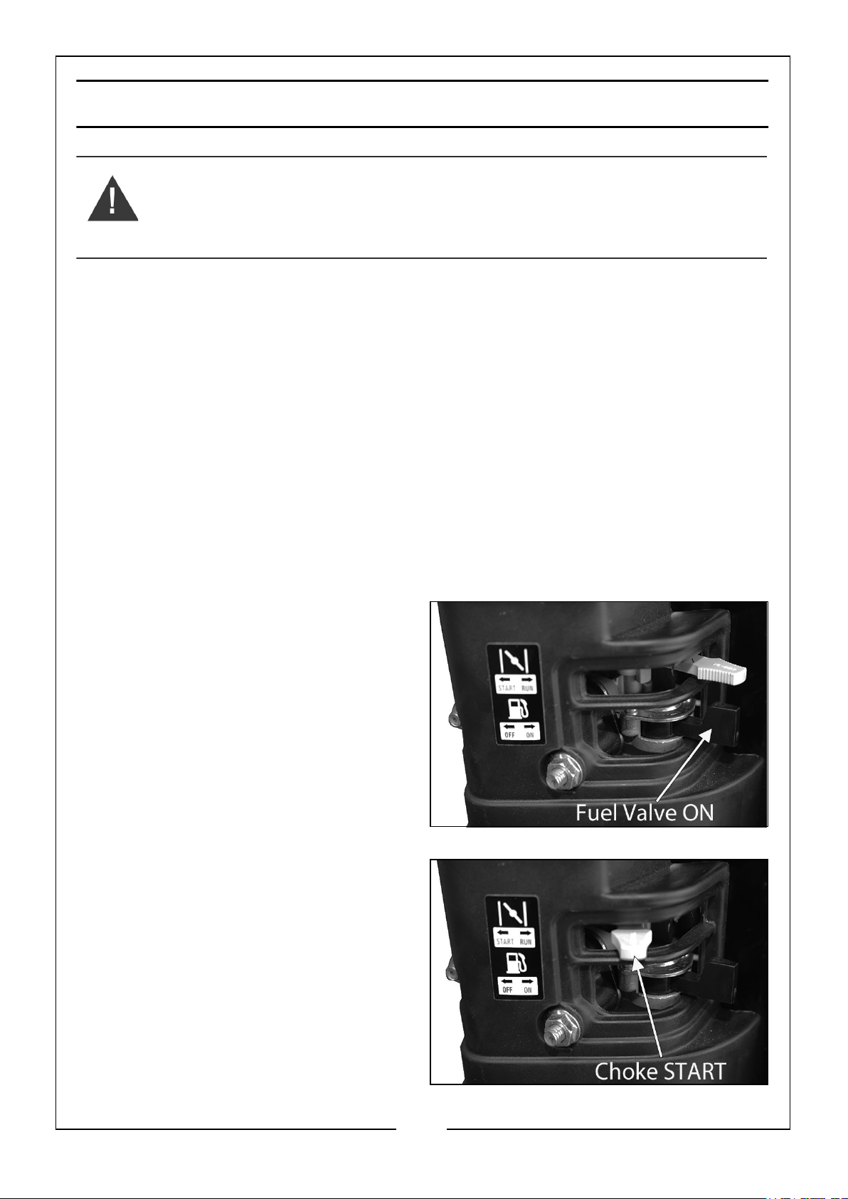
1. Slide the Fuel Valve Lever to the ‘ON’
position to allow the fuel to flow to
the engine.
2. Slide the Choke Lever to the ‘START’
position.
18
Parts & Service: 020 8988 7400 / E-mail: [email protected] or [email protected]
Page 19
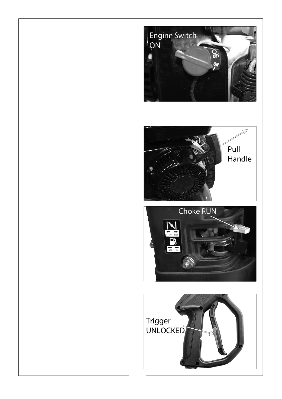
3. Turn the Engine Switch clockwise to
the ‘ON’ position.
4. Point the spray gun in a safe direction and squeeze the trigger to release any
pressure that may be in the system.
5. To start the engine, pull the Starter
Handle slowly until resistance is felt,
then pull rapidly to avoid kick back.
Repeat until the engine starts to run.
6. Slowly return the Starter Handle to its
original position to avoid injury/
damage as it recoils.
7. Once the engine has been running
for a few minutes, move the Choke
Lever to the ‘RUN’ position.
• The pressure washer is now ready
to be used.
8. Move the trigger lock to the
‘UNLOCKED’ position.
9. Ensuring that you have a firm footing
and that you are also holding the gun
assembly and spray lance firmly, pull
the trigger on the gun to start water
flow.
• The lance and gun will kick back
when the trigger is first pulled.
19
Parts & Service: 020 8988 7400 / E-mail: [email protected] or [email protected]
Page 20
INTERRUPTING OPERATION
1. Release the trigger on the spray gun.
NOTE: The pressure washer will automatically go into bypass mode.
WARNING: DO NOT ALLOW THE UNIT TO OPERATE IN BYPASS
MODE FOR MORE THEN TWO MINUTES AT ANY TIME. TURN THE
UNIT OFF IF IT IS NOT GOING TO BE USED FOR LONGER THAN THIS.
SEE PAGE 22.
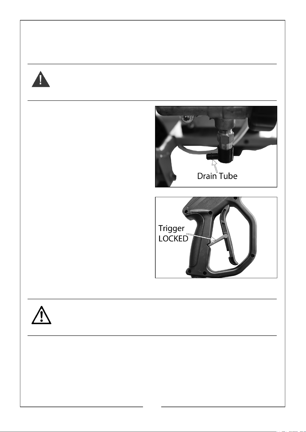
NOTE: If you notice water coming from
the drain tube at the bottom of
the pump, please note that this is
a safety feature and should be
expected, it cools the pump by
releasing some of the hot water
within the pump and replacing it
with fresh ‘cool’ water.
2. Move the trigger lock to the ‘LOCKED’
position.
APPLYING DETERGENTS AND CLEANING AGENTS
CAUTION: IF YOU GET DETERGENT/CLEANING AGENT IN YOUR
EYES, RINSE THEM IMMEDIATELY WITH PLENTY OF FRESH CLEAN
WATER. AND SEEK MEDICAL ADVICE IF REQUIRED.
To improve the cleaning performance, you can introduce chemical cleaning agents
(detergents) to the water jet using the detergent pickup tank and hose.
1. Attach the ‘BLACK’ nozzle to the spray gun lance, see pages 14-15.
20
Parts & Service: 020 8988 7400 / E-mail: [email protected] or [email protected]
Page 21
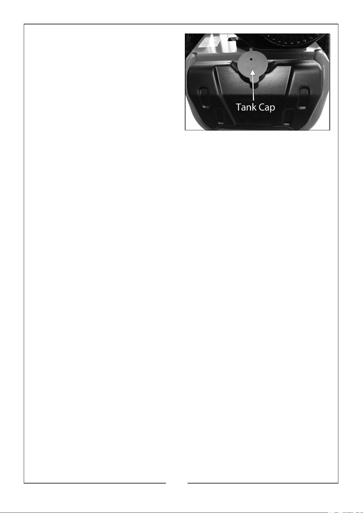
2. Remove the detergent tank cap.
3. Fill the tank with a suitable quantity
(maximum 2 litres) of cleaning
detergent and replace the cap.
• Only use detergents
recommended for use with
pressure washers, such as CLARKE
products listed below, all available
from your CLARKE dealer, see
page 39.
4. Spray the detergent onto the vehicle, patio etc.
• Allow the detergent a little time to work itself into the grime.
• To rinse, change the nozzle on the lance to either the red, yellow, green or
white one, depending on the work requirement, see pages 14-15, and use the
pressure washer as normal.
21
Parts & Service: 020 8988 7400 / E-mail: [email protected] or [email protected]
Page 22
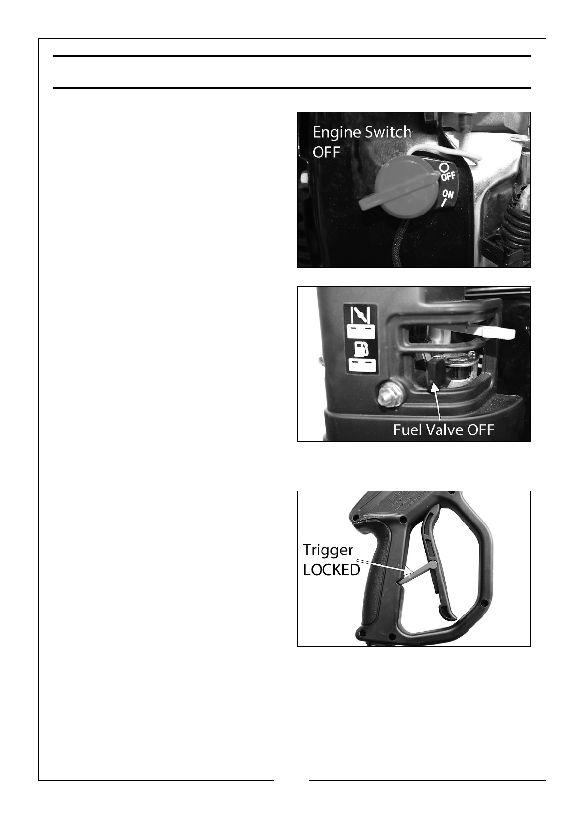
SHUTTING DOWN YOUR PRESSURE WASHER
1. To stop the engine, turn the Engine
Switch to the ‘OFF’ position.
2. Slide the Fuel Valve Lever to the left
to the ‘OFF’ position.
3. Turn off the water supply and
disconnect the garden hose from the
pressure washer.
• NEVER turn the water off with the
engine running.
4. Release the pressure in the pump
and hose by squeezing the trigger for a few seconds until no more water comes
out of the nozzle.
5. Move the trigger lock to the ‘LOCKED’
position.
22
Parts & Service: 020 8988 7400 / E-mail: [email protected] or [email protected]
Page 23

STORAGE
1. Disconnect the high pressure hose and inlet hose and drain all water from the
hoses.
2. Coil the hoses and store on the hose hook on the rear of the washer.
3. Dismantle and store the gun/lance in the holder located on the side frame of the
pressure washer.
STORAGE PROCEDURE
Make sure that the pressure washer has been thoroughly cleaned before storing it in
a clean dry place.
LONG TERM STORAGE
For long term storage;
1. The petrol tank should be drained.
• Ensure that the engine is cold before draining the tank.
2. Remove the fuel tank cap and use a pump type syphon to drain the petrol into an
appropriate, clean container.
• DO NOT store petrol for long periods of time.
• Dispose of excess petrol and oil in an environmentally safe way. Your local
recycling centre can advise you on the best method of disposal.
3. After the petrol tank has been drained, start the engine and allow it to use any
petrol that may remain in the engine, or fuel pipe.
4. Make sure that the pressure washer has been thoroughly cleaned before storing it
in a clean dry place.
23
Parts & Service: 020 8988 7400 / E-mail: [email protected] or [email protected]
Page 24
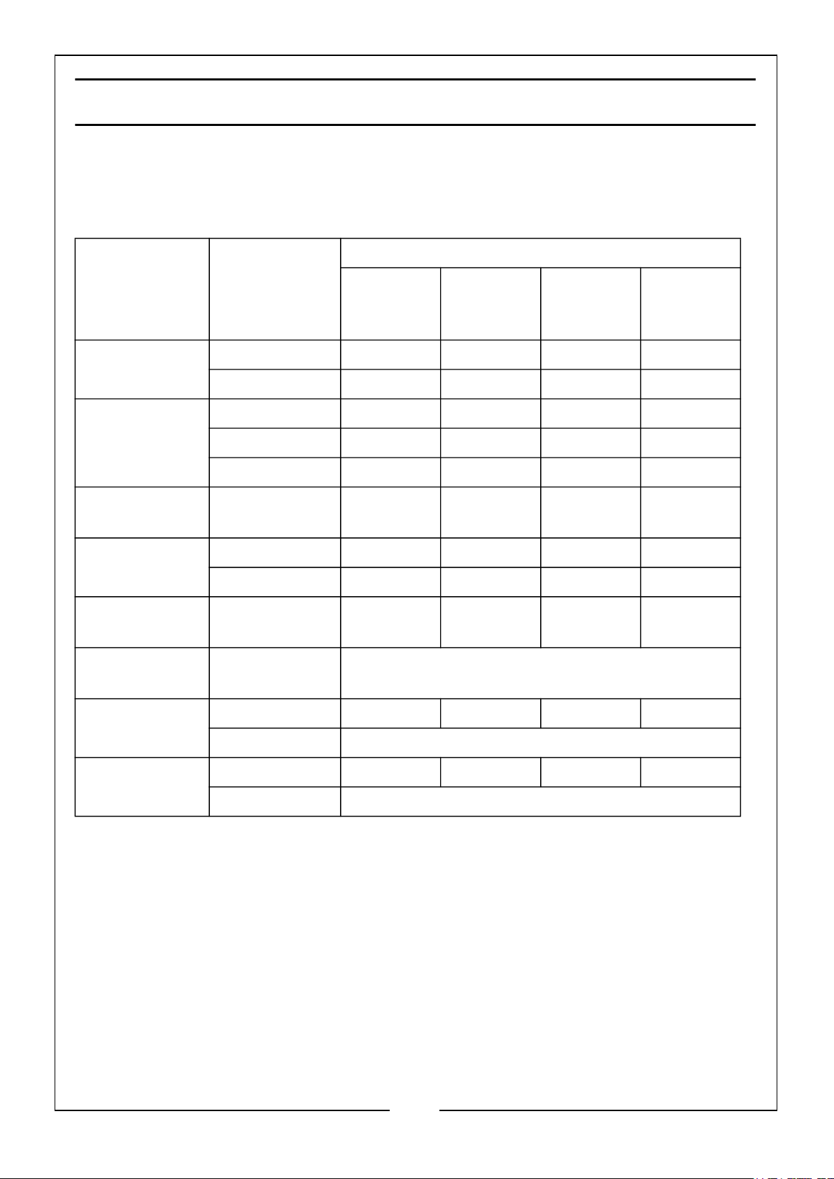
MAINTENANCE
Some adjustments will need to be made periodically to properly maintain the pressure
washer. All service and adjustments should be made at least one time each season. It
is important that the maintenance chart below is followed:
Frequency
Item Action
Engine Oil
(Page 16)
Air Filter
(Page 26-27)
Detergent Tank
(Page 28)
Spark Plug
(Page 27-28)
Fuel Filter
(page 26)
Fuel Supply
Line
Each Time
of Use
Check Level *
Replace *
Check *
Clean * **
Replace *
Clean *
Clean - Adjust ****
Replace *
Check - Clean *
Check Every Two Years (Replace if Necessary***)
Every 3
Months or
50 Hrs
Every 6
Months or
100 Hrs
Every Year
or 300 Hrs
Nozzles
(Page 25)
Water Inlet
Filter (Page 25)
• ** = Recommended to be performed more often than in the schedule if
operated in a dusty environment.
• *** = Recommended to be performed by a CLARKE authorized dealer.
• **** = Adjust air gap to 0.6 - 0.7 mm.
Parts & Service: 020 8988 7400 / E-mail: [email protected] or [email protected]
Check *
Clean If and When Required
Check *
Clean If and When Required
24
Page 25
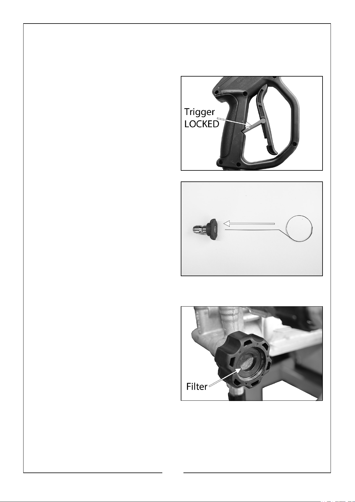
CLEANING THE NOZZLES
1. Switch off the pressure washer and the water supply.
2. Pull the trigger to release any water pressure.
3. Move the trigger lock to the ‘LOCKED’
position.
4. Disconnect the nozzle from the lance.
5. Remove all blockages with the nozzle
cleaning tool provided and back flush
with clean water.
6. Reconnect the nozzle and lance, turn
on the water supply and restart the
washer.
CLEANING THE WATER INLET FILTER
1. Remove the filter from the water inlet
of the pump.
2. Clean the filter by flushing both sides
with water.
3. Replace the filter into the water inlet.
• DO NOT operate without the filter
properly installed or damaged.
25
Parts & Service: 020 8988 7400 / E-mail: [email protected] or [email protected]
Page 26
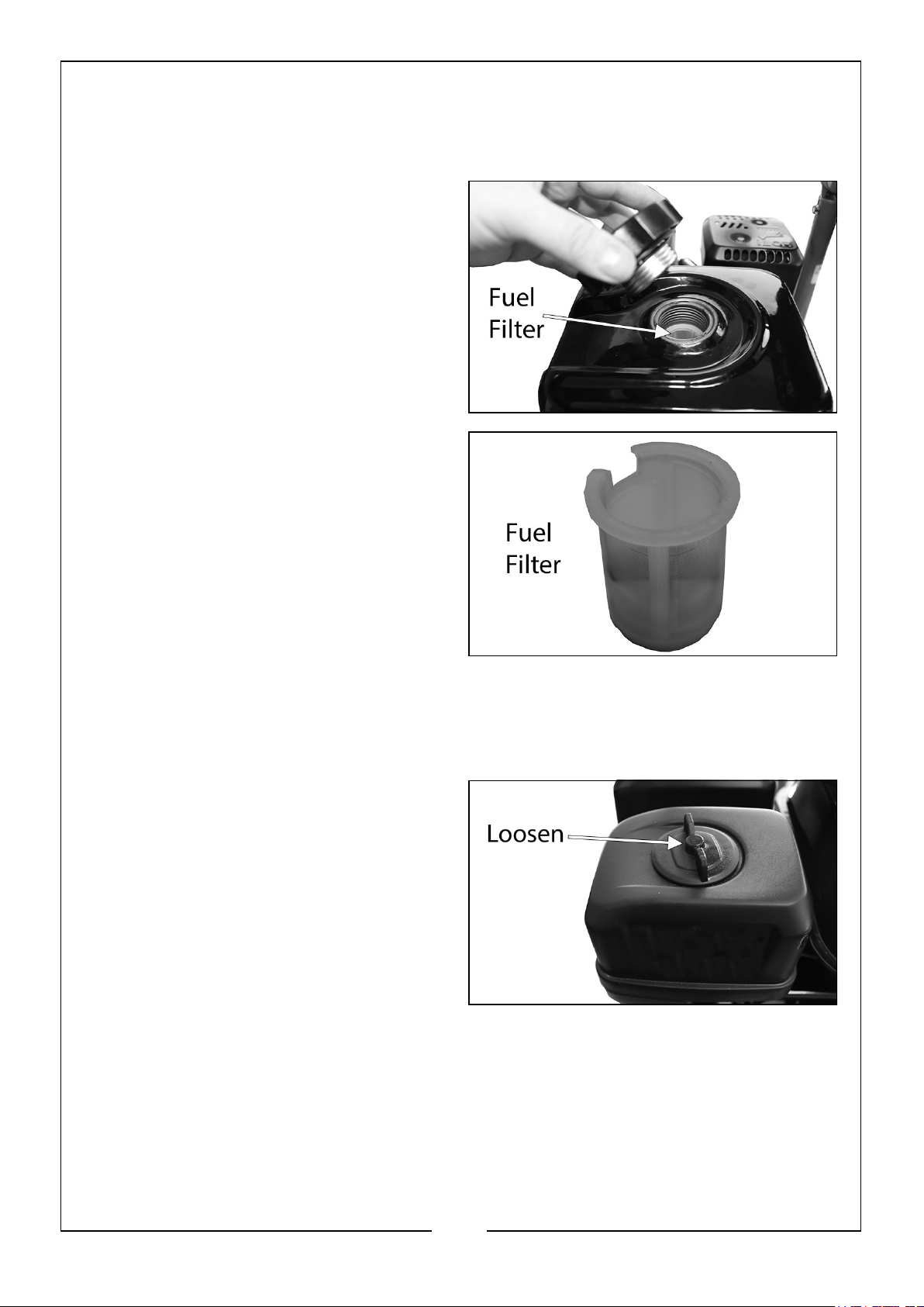
CLEANING THE FUEL FILTER
Just inside the fuel tank is a fuel filter, check this periodically and remove any
contaminants which may have accumulated.
1. Open the fuel tank cap.
2. Remove the fuel filter.
3. Flush away any contaminants.
4. Replace the fuel filter.
• DO NOT operate the pressure
washer without the fuel filter
properly installed or damaged.
CLEANING THE AIR FILTER
1. Loosen the screw on top of the air
filter cover.
2. Remove the air filter cover.
26
Parts & Service: 020 8988 7400 / E-mail: [email protected] or [email protected]
Page 27
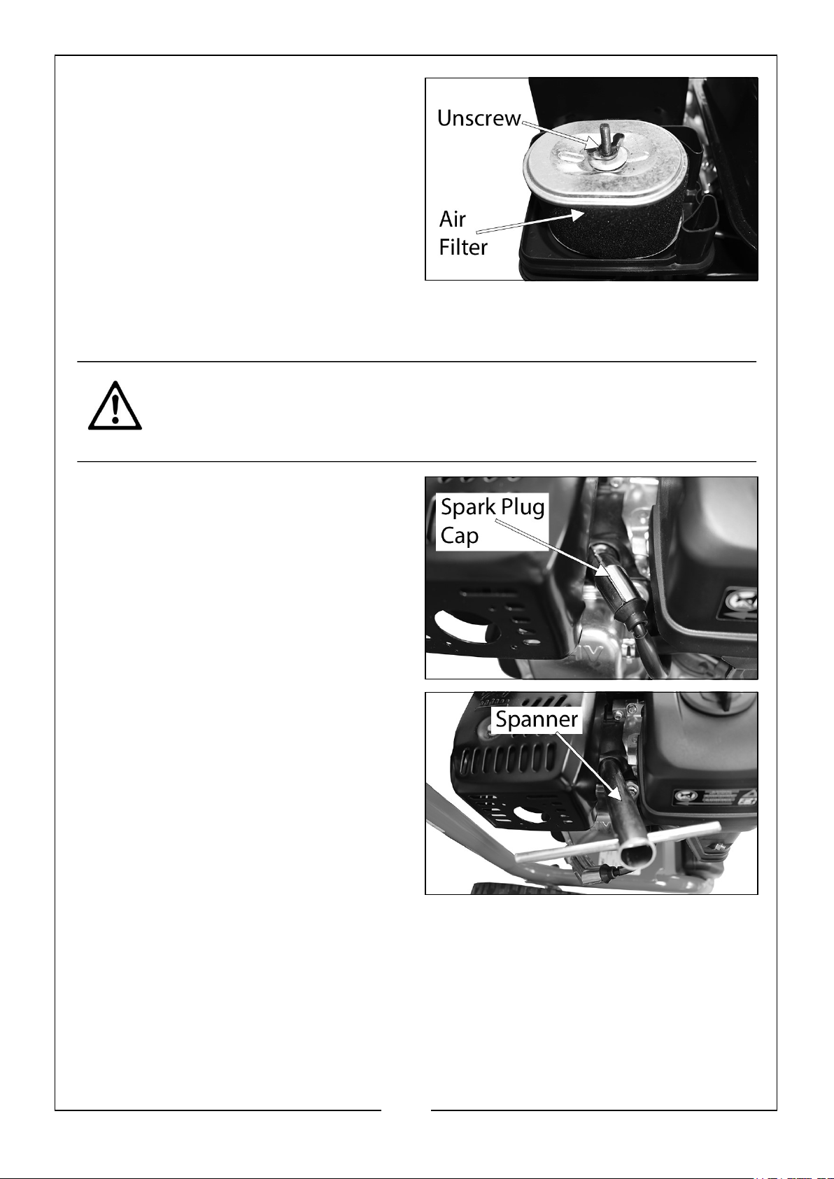
3. Loosen and remove the wingnut
holding the air filter in place.
4. Remove the air filter element.
5. Thoroughly vacuum the filter and
check for any damage.
• If the air filter is damaged contact
CLARKE spare parts department
for a replacement.
6. Replace the filter into its original position and reattach the air filter cover.
CHANGING THE SPARK PLUGS
CAUTION: ALLOW THE ENGINE AND MUFFLER TO COOL BEFORE
REMOVING THE SPARK PLUG.
1. Remove the spark plug cap from the
spark plug.
2. Use the supplied spark plug spanner
to remove the spark plug.
3. Remove any carbon that has
accumulated around the spark-plug.
27
Parts & Service: 020 8988 7400 / E-mail: [email protected] or [email protected]
Page 28
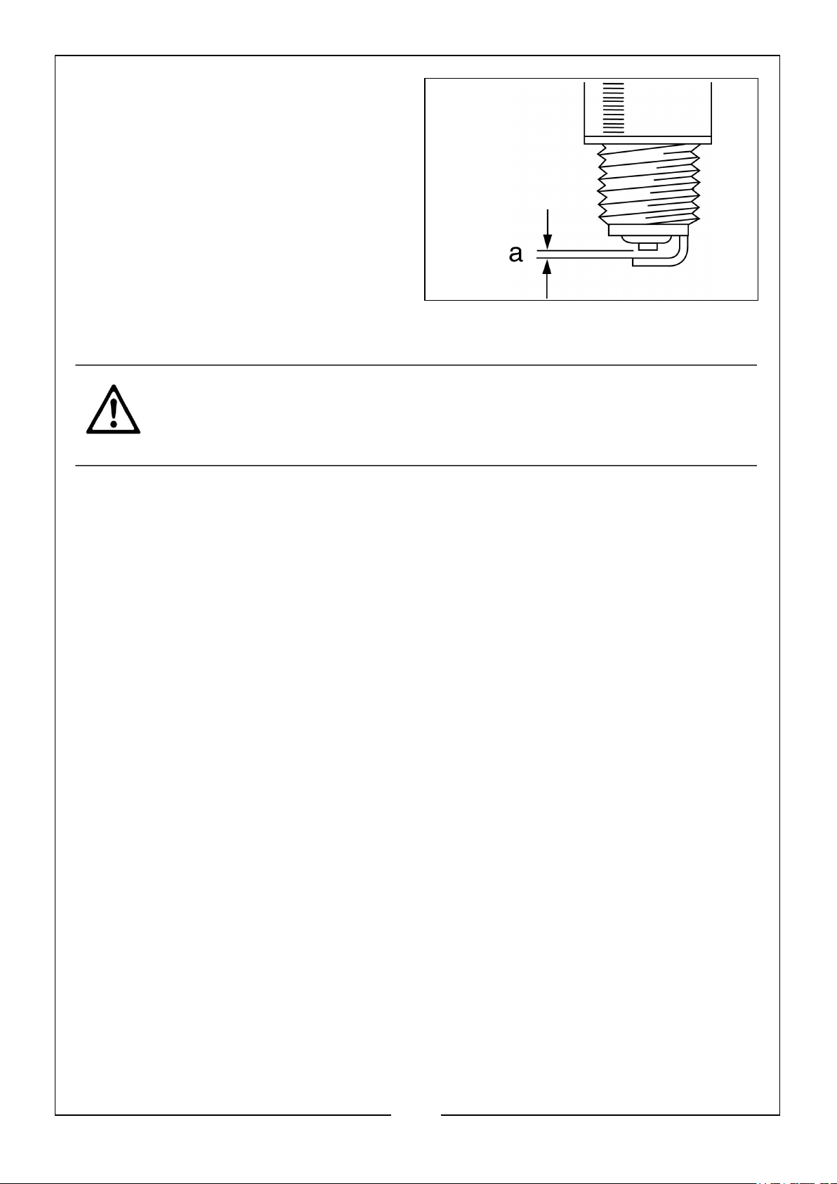
4. Check the overall condition of the
spark plug and replace if necessary.
5. Check the spark plug gap (a), it
should be between 0.6 and 0.7 mm,
adjust if necessary.
6. Reinstall the spark plug and refit the
spark plug cap.
CLEANING THE DETERGENT TANK
CAUTION: LEAVING CHEMICALS AND DETERGENTS INSIDE THE
PRESSURE PUMP COULD DAMAGE IT.
1. Turn off the engine and fill the detergent tank with clean water.
2. Remove the Black detergent nozzle and replace with the White nozzle.
3. Turn on the pressure washer.
4. Point the spray gun in a safe direction and squeeze the trigger to flush the clean
water through the detergent tank and the system until it is thoroughly clean.
28
Parts & Service: 020 8988 7400 / E-mail: [email protected] or [email protected]
Page 29
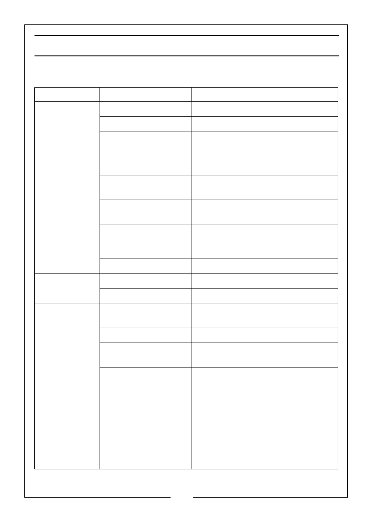
TROUBLESHOOTING
If the following does not solve your problem contact the CLARKE service dept.
PROBLEM CAUSE SOLUTION
Engine will not
start (see engine
manual for
further engine
troubleshooting)
Oil leaking at the
pump
No fuel. Add fuel, see page 17.
Low oil. Add oil, see page 16.
Pressure builds up after
two pulls on the recoil
starter or after initial
use.
Spark plug lead not
attached.
Engine switch is in the
OFF position.
Choke lever is set to the
ON position when the
engine is already warm.
Fuel valve closed. Open the fuel valve.
Oil seals worn. Have them replaced by your dealer.
Worn O-rings. Have them replaced by your dealer.
Squeeze the gun trigger to relieve the
pressure.
Attach the spark plug lead.
Set the engine switch to the ON position.
Set the choke lever to the OFF (right)
position.
Lack of pressure
(initial use)
Leak in the high
pressure hose fitting.
Nozzle is obstructed. Clear the nozzle.
Water filter screen is
clogged.
Air in the hose. Turn off the engine.
Tighten the fitting, use sealant tape if
required.
Remove and clean the filter.
Turn off the water supply.
Disconnect the water source from the
pump inlet and turn on the water source
to expel the air from the hose.
When all the air has been removed, turn
off the water supply and reconnect the
hose.
Turn on the water supply and pull the
trigger to expel any air in the gun/lance.
29
Parts & Service: 020 8988 7400 / E-mail: [email protected] or [email protected]
Page 30
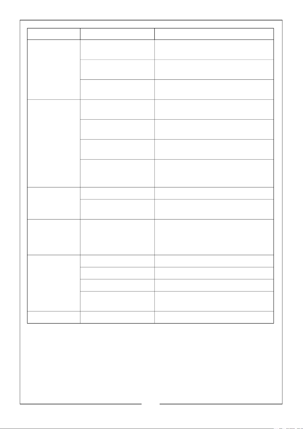
PROBLEM CAUSE SOLUTION
Lack of pressure
(initial use)
Will not draw
detergent
Lack of pressure
(after a period of
normal use)
Choke lever is in the ON
Set the choke lever to the OFF position.
position.
Throttle control lever is
Move the throttle control lever to left.
not set high enough.
High pressure hose is
too long.
Chemical pipe is
Make sure the high pressure hose is
under 100 feet.
Clean the pipe.
blocked.
Detergent being used is
too thick.
High pressure hose is
too long.
Detergent build up
inside the detergent
Dilute the detergent which should have
the consistency of water.
Use a longer supply hose instead of a
longer high pressure hose.
Have the parts cleaned or replaced by
your dealer.
injector.
Worn seal or packing. Have them replaced by your dealer.
Worn or obstructed
Have them replaced by your dealer.
valves.
Water leaking
from the drain
hose
Pump is overheating This is a safety feature and should be
expected. It cools the pump by releasing
some of the hot water within the pump
and replacing it with fresh ‘cool’ water.
Water leaking at
Loose connections. Tighten.
the pump
Piston rings worn. Have it replaced by your dealer.
Damaged O-rings. Have it replaced by your dealer.
Pump head or tubes
damaged from freezing.
Have it replaced by your dealer. See
‘Storage’ on page 23.
Pump pulsates Nozzle obstructed. Clear the nozzle.
30
Parts & Service: 020 8988 7400 / E-mail: [email protected] or [email protected]
Page 31
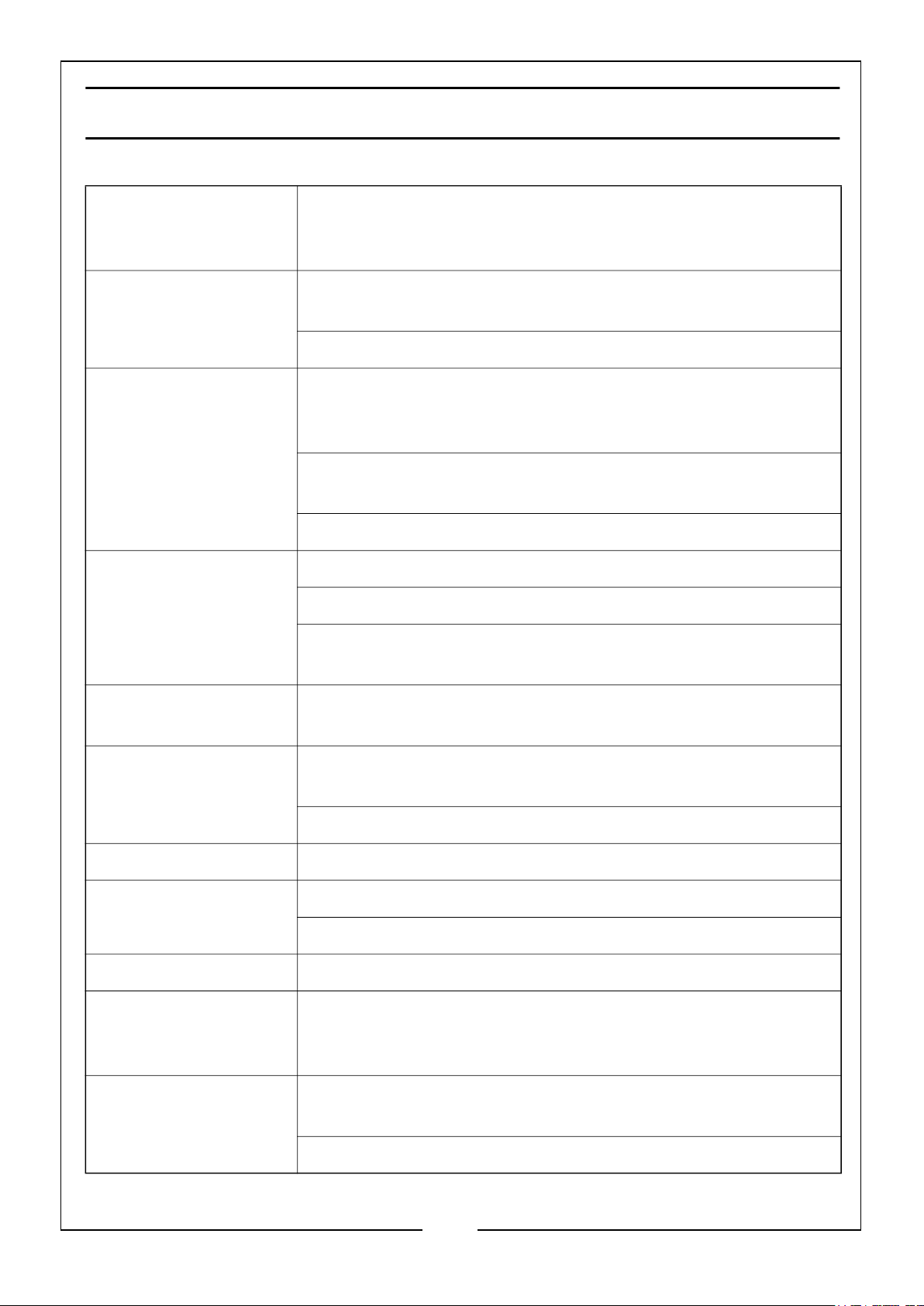
GLOSSARY
Bypass Mode NEVER leave the unit running for more than 2 minutes
without squeezing the spray gun trigger. Doing so could
damage the pump and void the warranty.
Detergents Only use soaps and chemical detergents designed for
pressure washer use
Use the Black detergent nozzle when using a detergent
Engine DO NOT adjust or attempt maintenance without consulting
the supplied engine manual or having adjustments made at
an authorized service centre
Add stabilizer to the fuel tank and let the engine run for 5
minutes before storing for any length of time.
ALWAYS turn on the water supply before starting the engine
Fuel Use fresh high quality unleaded petrol (minimum E10)
Safe maximum fuel quantity for the tank is 2.3 litres
Add stabilizer to the fuel tank and run the engine for 5
minutes before storing for any length of time.
GPM Gallons per minute (litres per minute, metric) - common unit
of measurement used for the flow rate of water.
Hose DO NOT allow the hoses to come into contact with the
engine muffler during or immediately after use
DO NOT pull the unit by the pressure hose
Nozzles ALWAYS keep nozzles unclogged
Oil Use only SAE10W-30 non-detergent oil
Maximum oil quantity for the engine is 600ml
Pressure Adjustment The pressure setting has been preset at the factory
PSI Pounds per square inch - common unit of measurement used
for water pressure, air pressure, hydraulic pressure and
pounds of force.
Pump Squeeze the spray gun trigger every 2 minutes while the
engine is still running
DO NOT allow water to freeze in the pump
31
Parts & Service: 020 8988 7400 / E-mail: [email protected] or [email protected]
Page 32
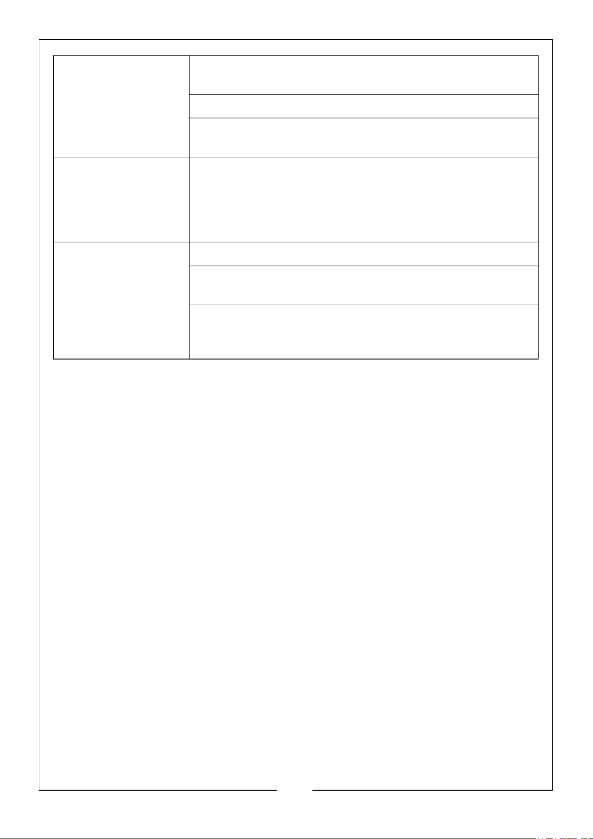
Storage Before storage, run clean water through the detergent tank
and inlet pipe
Add stabilizer to any remaining fuel in the fuel tank
DO NOT allow water to freeze in the pressure pump, spray
gun, lance or hoses
Thermal Release Valve When in Bypass Mode, this valve releases a jet of water to
prevent the water temperature from reaching harmful levels
that may damage the pump. Once the water has cooled, the
thermal relief valve will reset itself. DO NOT allow the pump
to run without using the spray gun for more than 5 minutes.
Water Use only cold water
DO NOT operate the pressure washer with a clogged,
missing or damaged water inlet filter, see page 25
DO NOT operate the pressure washer without adequate
water supply to the pressure pump. Adequate water supply
should be a minimum of 18.92 l/min (1135.2 l/hr) / 5 GPM
32
Parts & Service: 020 8988 7400 / E-mail: [email protected] or [email protected]
Page 33
Page 34
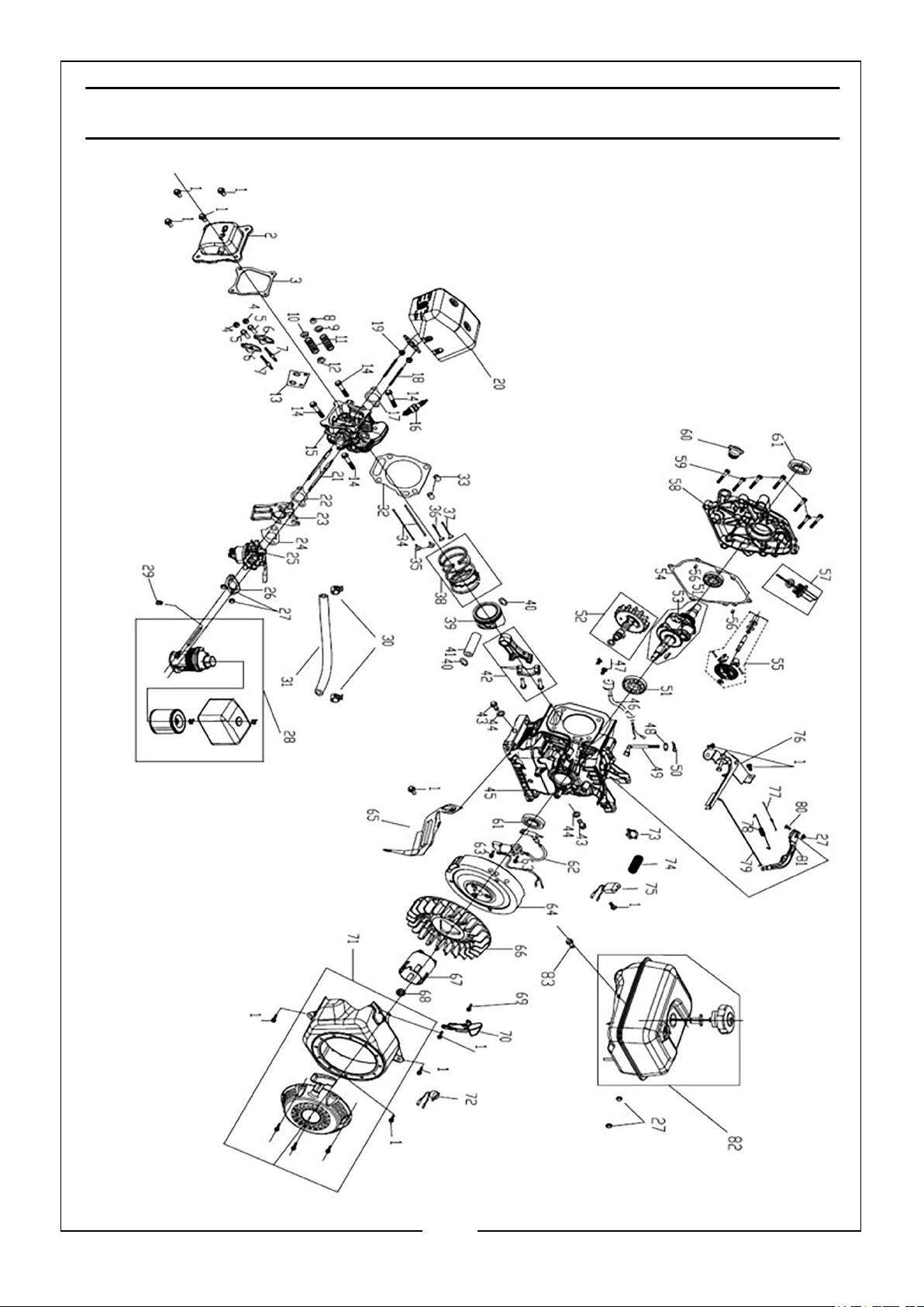
COMPONENT PARTS LIST
NO DESCRIPTION NO DESCRIPTION
1 M6 x 12 Bolt x 13 31 Fuel Pipe
2 Head Cover 32 Cylinder Gasket
3 Head Cover Gasket 33 Dowel Pin x 2
4 Nut, Valve Adjusting x 2 34 Push Rod x 2
5 Rocker Shaft x 2 35 Lifter Valve x 2
6 Rocker Arm x 2 36 Intake Valve
7 Bolt Valve x 2 37 Exhaust Valve
8 Rotator Valve 38 Piston Ring Set
9 Retainer Valve Spring 39 Piston
10 Retainer Valve Spring 40 Piston Pin Clip x 2
11 Spring Valve x 2 41 Piston Pin
12 Oil Intake Shield 42 Connecting Rod Assembly
13 Push Rod Guide Plate 43 M10 x 15 Bolt x 2
14 M8 x 50 Bolt x 2 44 Washer x 2
15 Cylinder Head 45 Crankcase
16 Spark Plug 46 Engine Oil Sensor
17 Muffler Washer 47 M6 x 16 Bolt x 2
18 Exhaust Bolt, Stud x 2 48 Washer
19 M8 Nut x 2 49 Governor Shaft
20 Muffler Assembly 50 Lock Pin
21 Intake Bolt, Stud x 2 51 Bearing x 2
22 Inlet Gasket 52 Camshaft Assembly
23 Carburetor Connector 53 Crankshaft Assembly
24 Carburetor Washer 54 Crankshaft Cover Gasket
25 Carburetor 55 Governor Gear Kit
26 Air Filter Gasket 56 Dowel Pin x 2
27 Flange Nut x 2 57 Dipstick Assembly
28 Air Filter Assembly 58 Crankshaft Cover
29 Tube Clip 59 M8 x 32 Bolt x 6
30 Clip 60 Oil Cap Assembly
34
Parts & Service: 020 8988 7400 / E-mail: [email protected] or [email protected]
Page 35
NO DESCRIPTION NO DESCRIPTION
61 Oil Seal x 2 73 Non Return Valve Clip
62 Engine Switch Wire 74 Bellows
63 Flange Bolt x 2 75 Oil Alarm
64 Flywheel 76 Speed Control Assembly
65 Side Shell 77 Throttle Return Spring
66 Cooling Fan 78 Cable Return Spring
67 Starter Pulley 79 Governor Rod
68 Special Nut 80 Bolt
69 Flange Bolt 81 Speed Control Handle
70 Side Shell 82 Fuel Tank Assembly
71 Recoil Starter 83 Flange Bolt x 2
72 Engine Switch
35
Parts & Service: 020 8988 7400 / E-mail: [email protected] or [email protected]
Page 36
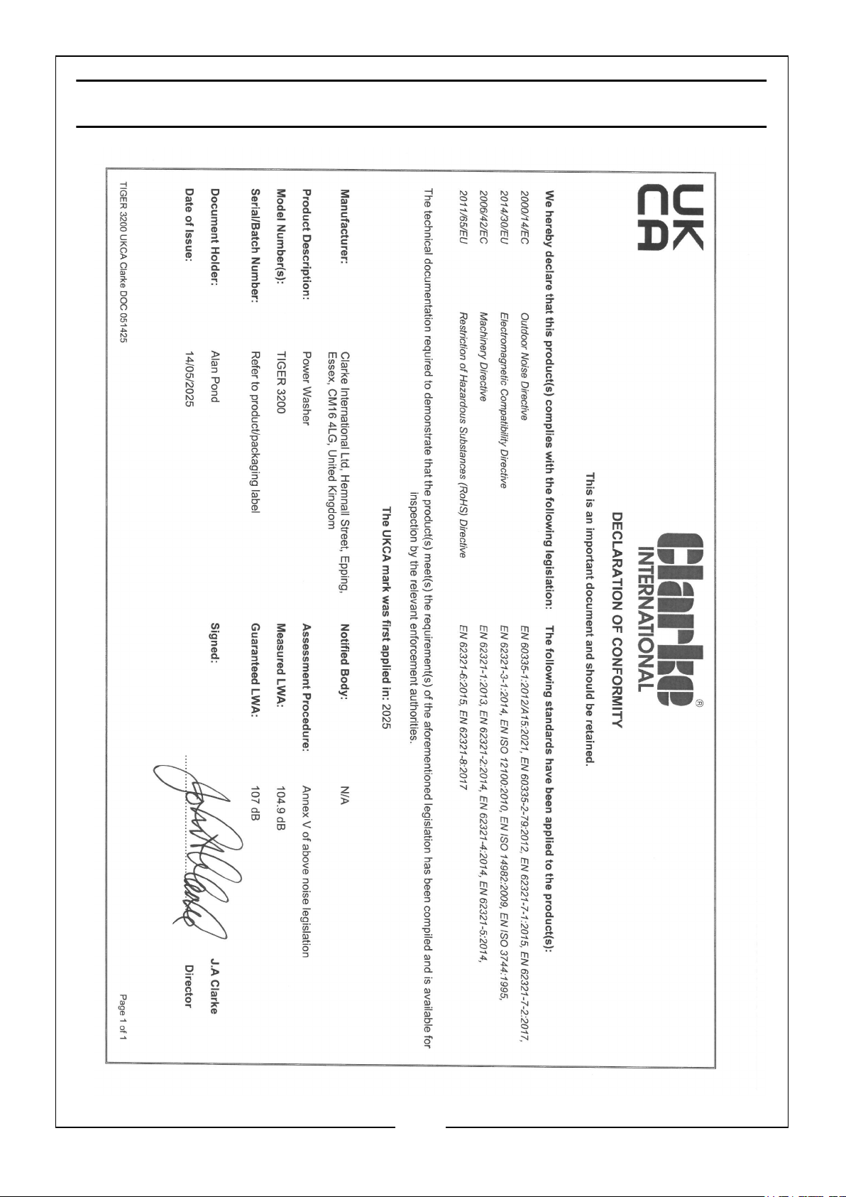
DECLARATIONS OF CONFORMITY - UKCA
36
Parts & Service: 020 8988 7400 / E-mail: [email protected] or [email protected]
Page 37
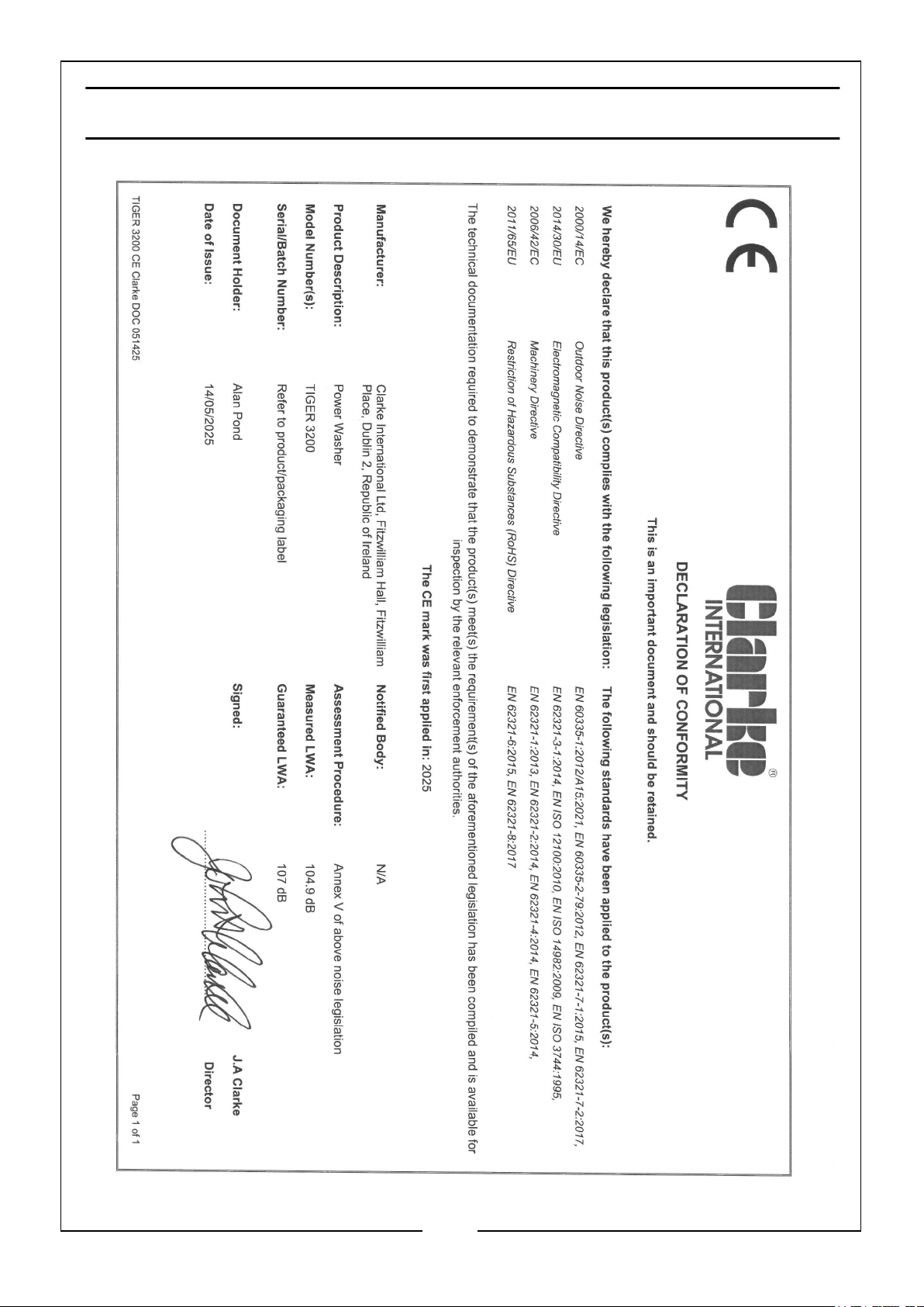
DECLARATIONS OF CONFORMITY - CE
37
Parts & Service: 020 8988 7400 / E-mail: [email protected] or [email protected]
Page 38
SPECIFICATIONS
Model Tiger 3200
Engine Model AP170F
Power & RPM 7hp / 4.0kW / 3600rpm
Engine Type & Size Petrol (unleaded), 208cc
Starting System Pull / Recoil
Safe Fuel Tank Capacity (L) 2.3
Fuel Consumption (L/Hr) 0.9 Approx.
Oil Capacity (L) & Grade 0.6 / SAE10W-30
Input Water Temperature
Max Flow Rated/Measured (l/min) 8.7 / 9.7
Maximum Pressure 3200 Psi / 220 Bar
Working Pressure 2700 Psi / 186 Bar
Detergent Tank Capacity (L) 2.5
IP Rating IP20
Max. Dimensions (D x W x H) 540mm x 510mm x 1020mm
High Pressure Outlet Hose Length (metres) 10
Water Supply Inlet Hose Length (metres) 3
Weight (kg) 30
Sound Pressure Level dB (A) 91
0oC - 40oC
Sound Power Level dB (A) 104.9
Guaranteed Sound Pressure Level dB (A) 107
Uncertainty Factor LWA dB 2.5
Engine Emissions (CO/HC/Nox/HC+Nox/CO2) g/kWh 282.89/3.74/3.15/6.88/
730.70
38
Parts & Service: 020 8988 7400 / E-mail: [email protected] or [email protected]
Page 39
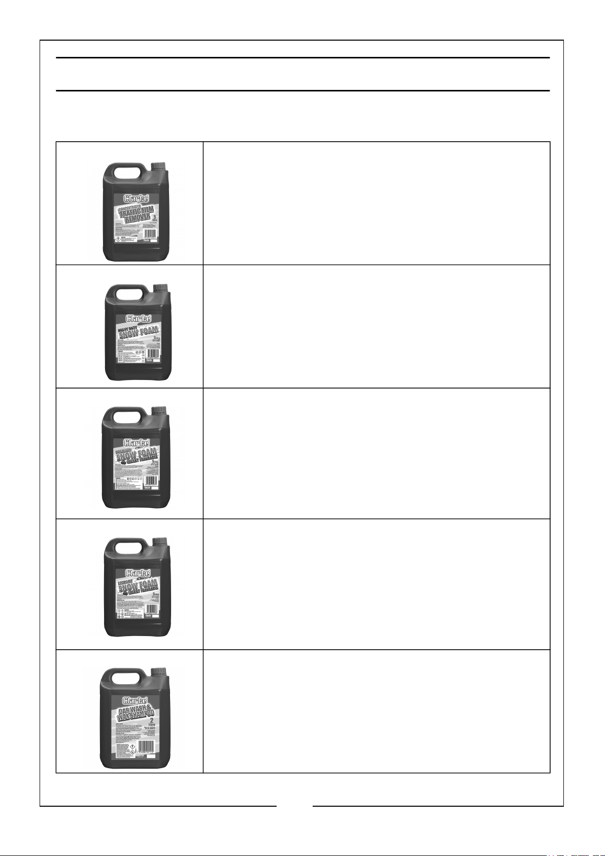
ASSOCIATED PRODUCTS
Concentrated Traffic Film Remover, 5 Litres.
Can be used to clean grime off all vehicles. It can also clean
engines and chassis.
Part Number: 3050821
Heavy Duty Snow Foam, 5 Litres.
Can be used to lift the toughest dirt. Suitable for off-road
vehicles, tractors, trucks and motorcycles.
Part Number: 3050807
Premium Snow Foam with Cherry Fragrance, 5
Litres.
Contains finishing gloss treatment. Contains no caustic or
harmful chemicals and will easily clean and leave a premium
gloss finish.
Part Number: 3050806
Economy Snow Foam with Cherry Fragrance, 5
Litres.
Contains finishing gloss treatment. Contains no caustic or
harmful chemicals and will easily clean and leave a gloss
finish.
Part Number: 3050805
Wash & Wax Car Shampoo, 2 Litres.
Penetrates dirt and grime. With added foam booster, lifts
any damaging particles to leave a glossy finish on chrome
and bodywork.
Part Number: 3050817
39
Parts & Service: 020 8988 7400 / E-mail: [email protected] or [email protected]
Page 40

 Loading...