

Page 1
Operator's
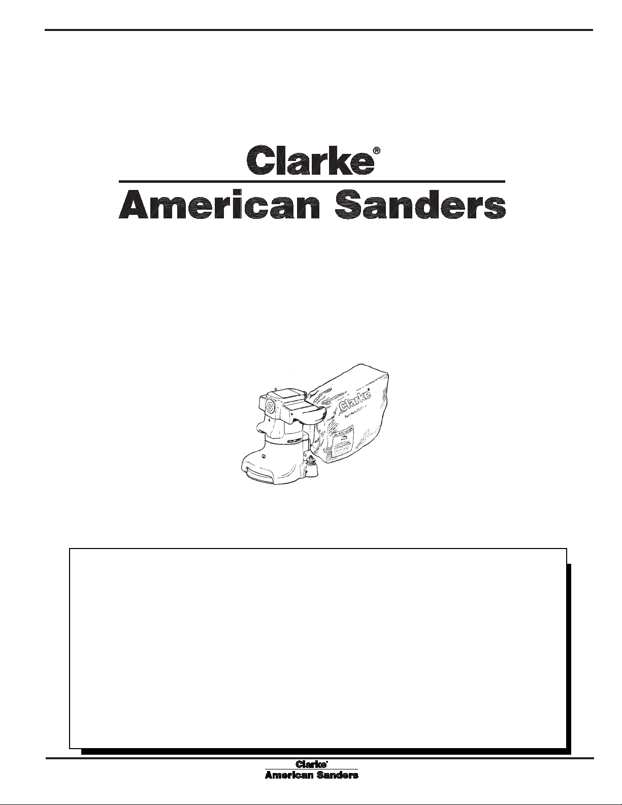
Super 7R
Manual
DC Edger
READ THIS BOOK
This book has important information for the use and safe operation of this machine. Failure to read
this book prior to operating or attempting any service or maintenance procedure to your Clarke
American Sanders machine could result in injury to you or to other personnel; damage to the machine
or to other property could occur as well. You must have training in the operation of this machine
before using it. If you cannot read English, have this manual explained fully before attempting to
operate this machine.
Si Ud. no pueden leer el Inglés, se hagan explicar este manual completamente antes de tratar el
manejo o servicio de esta máquina.
All directions given in this book are as seen from the operator’s position at the rear of the machine.
For new books write to: Clarke
®
, 2100 Highway 265, Springdale, Arkansas 72764.
Form No. 70895A 11/04 Printed in the U.S.A.
Page 2

Contents of this Book
Operator's Manual - Section I
Operator Safety Instructions .........................................................3
Machine Specifications ................................................................5
Sanding Cuts and Sandpaper .................................................... 6
Machine Set-Up ...........................................................................7
Operating Instructions...................................................................8
Adjustment Procedures ................................................................9
Routine Maintenance....................................................................9
Maintenance ..............................................................................10
Parts and Service Manual - Section II
Assembly Drawing .....................................................................12
Assembly Parts List ...................................................................13
Wiring Diagram..........................................................................14
Page 2 Clarke® American Sanders Super 7R Operator's Manual
Page 3
OPERATOR SAFETY INSTRUCTIONS
WARNING AVERTISSEMENT ADVERTENCIA
DANGER means: Severe bodily injury or death can occur to you or other personnel if the DAN-
GER statements found on this machine or in this Operator's Manual are
ignored or are not adhered to. Read and observe all DANGER statements
found in this Operator's Manual and on your machine.
WARNING means: Injury can occur to you or to other personnel if the WARNING statements
found on your machine or in this Operator's Manual are ignored or are not
adhered to. Read and observe all WARNING statements found in this
Operator's Manual and on your machine.
CAUTION means: Damage can occur to the machine or to other property if the CAUTION state-
ments found on your machine or in this Operator's Manual are ignored or are
not adhered to. Read and observe all CAUTION statements found in this
Operator's Manual and on your machine.
DANGER: Failure to read the Operator's Manual before operating or servicing this sanding equipment
could result in injury to the operator or to bystanders and could cause damage to the
equipment. Read and observe all safety statements found in this manual and on the
sanding equipment. Make sure all labels, decals, warnings, cautions and instructions are
fastened to the equipment. Replace any that are damaged or missing. You must have
training in the operation of this equipment before using it. If the operator is unable to
read this manual, have it explained fully before they attempt to use this equipment.
DANGER: Sanding/finishing wood floors can create an environment that can be explosive. The
following safety procedures must be adhered to:
• Cigarette lighters, pilot lights and any other source of ignition can create an explosion
when active during a sanding session. All sources of ignition should be extinguished or
removed entirely if possible from the work area.
• Work areas that are poorly ventilated can create an explosive environment when certain
combustible materials are in the atmosphere, i.e., solvents, thinners, alcohol, fuels,
certain finishes, wood dust and other combustible materials. Floor sanding equipment
can cause flammable material and vapors to burn. Read the manufacturer's label on all
chemicals used to determine combustibility. Keep the work area well ventilated.
• Spontaneous combustion or an explosion can occur when working with sanding dust.
The sanding dust can self-ignite and cause injury or damage. Sanding dust should be
disposed of properly. Always empty the sanding dust into a metal container that is
located outside of any building(s).
• Remove the contents of the dust bag when the bag is 1/3 full. Remove the contents of
the dust bag each time you finish using the equipment. Never leave a dust bag unattended with sanding dust in it.
• Do not empty the contents of the dust bag into a fire.
• Hitting a nail while sanding can cause sparks and create an explosion or fire. Always
use a hammer and punch to countersink all nails before sanding floors.
Clarke® American Sanders Super 7R Operator's Manual Page 3
Page 4
DANGER: Operating partially assembled sanding equipment could result in injury to the operator or
bystander and could cause damage to the equipment or to other property.
• Do not operate this equipment unless it it fully assembled and all guards, doors and
covers are secured.
• Keep all fasteners tight.
• Keep all adjustments within manufacturers specifications.
DANGER: Moving parts on this sanding equipment can cause injury to the operator or bystanders.
• Keep hands, feet and loose clothing away from all moving parts.
• Do not change or adjust the abrasive while the sanding equipment is running.
• Do not service the sanding equipment while it is running.
DANGER: This sanding equipment requires a supply of electricity. Improper use could result in electrical
shock or fire.
• Connect only to an electrical source matching what is shown on the equipment nameplate.
• Do not use this sanding equipment on an ungrounded electrical circuit. Consult an
electrician if you suspect the circuit is not properly grounded.
• Do not use this sanding equipment with a damaged electrical cord. Inspect before each
use.
• Avoid striking the elelctrical cord with the abrasive. Always lift the electrical cord over
the sanding equipment.
• Do not use the electrical cord to move the sanding equipment.
• Disconnect the electrical source before servicing this equipment.
WARNING: Injury to the operator or bystander can occur if protective gear is not worn while sanding.
Always use eye, ear, and respiratory protection while performing any sanding operation.
WARNING: Bodily injury could occur if power is applied to the equipment with the power switch already
in the "ON" position. Always check to assure that the power switch is in the "OFF" position
before connecting power supply.
CAUTION: Maintenance and repairs performed by unauthorized personnel could result in damage or
injury. Maintenance and repairs performed by unauthorized personnel will void your warranty.
Servicing of this unit must always be referred to an authorized Clarke American Sanders
distributor.
CAUTION: Use of this equipment to move other objects or to climb on could result in injury or damage.
Do not use this equipment as a step or furniture. Do not ride on this equipment.
CAUTION: Damage could occur to the equipment if not properly kept in a dry building for storage. Store
the equipment in a dry building.
CAUTION: Serious damage to the floor can occur if the sanding equipment is left running in one spot while
the sanding disc is in contact with the floor. To avoid damage to the floor, do not dwell while
lowering or raising the sanding disc. Always sand with a constant motion.
Page 4 Clarke® American Sanders Super 7R Operator's Manual
Page 5
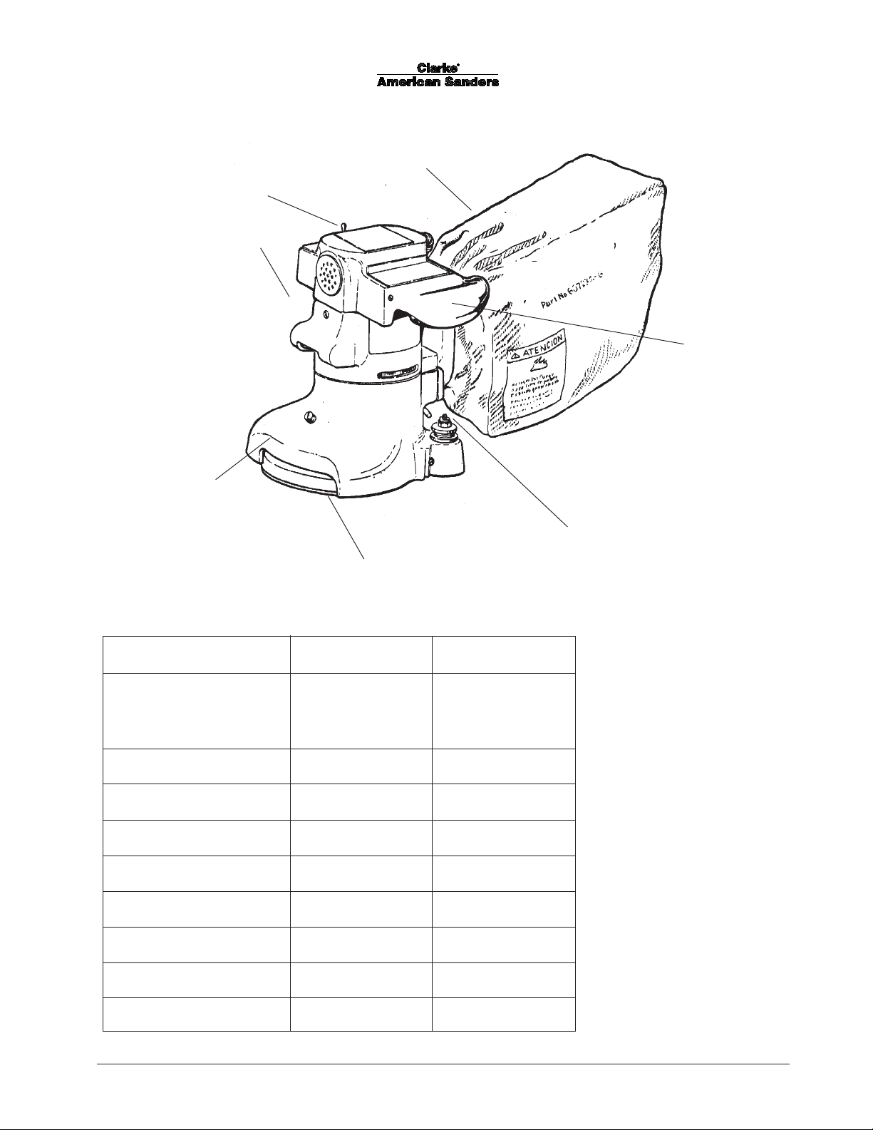
Control Switch
Work Light
Wall Guard
Model Super 7R
Specifications
Dust Collection Bag
Operating Handles
Steel Reinforced
Molded Rubber
Sanding Pad
Abrasive Wrench
Specifications
Model 07125A 07126A
Electrical Requirements 115V ~, 60 Hz 230V ~, 50 - 60 Hz
12.0A, 1.3 kW 6.0A, 1.3 kW
Storage Case Standard Standard
Motor Series Universal Series Universal
Abrasive Size 7" x 7/8" Dia. Disc 7" x 7/8" Dia. Disc
Disc Rate 2800 RPM 2800 RPM
Disc Driver System Gear Driven Gear Driven
Power Cable 14-3 Gray Rubber 14-3 Gray Rubber
Dust Collection Standard Standard
Dust Control Rate 110 CFM 110 CFM
Clarke® American Sanders Super 7R Operator's Manual Page 5
Page 6

SANDING CUTS AND SANDPAPER
Initial Cut
The purpose of the initial cut is to remove old finish and gross imperfections on the floor surface. A coarse
abrasive should be used.
If glazing, loading, or burning takes place immediately into an initial cut, select a coarser abrasive. If this
should occur during an initial cut, the abrasive has dulled and must be replaced.
Final Cuts
The purpose of a finishing cut is to remove the scratches produced during the initial cut. Use a fine (60 - 80
grit) grain abrasive.
If the surface remains rough after a finishing cut, it may be necessary to use an even finer grain of abrasive (80
- 100 grit). Care should be taken in selecting the grit size of the abrasive. A very fine grain will close the
pores on a wood floor making admission of a stain difficult.
7" Diameter 7" Diameter
Grain Use
12 grit For removing gross imperfections and
16 grit restore evenness to old flooring. To remove
20 grit build-up of paints and varnishes.
24 grit
30 grit For first sanding of new flooring (maple, oak).
36 grit For removing minor imperfections and finishes
from old flooring.
40 grit For initial cut on new flooring (oak, walnut).
For removing minor imperfections and finishes
from old flooring.
50 grit For first sanding of new flooring (cedar, pine,
fir) For clean-up of 16 grit.
60 grit For clean-up from initial cut 36 grit.
80 grit For final sanding of certain hardwoods. For
clean-up of initial cuts (50 grit).
100 grit For final sanding of certain hardwoods and
conifers where a smooth surface is desired.
Standard Grade
Part #/Qty
945300/50
945301/50
945302/50
945305/100
945307/100
945308/100
945309/100
945310/100
Professional Grade
Part #/Qty
945594/200
945595/200
945596/200
945597/300
945598/300
945599/300
945600/300
945601/300
945602/300
945603/300
945604/300
120 grit For final sanding of certain conifers.
150 grit For final sanding of certain conifers where a
945605/500
945606/300
smooth surface is desired for surface
roughening between coats of finish.
Page 6 Clarke® American Sanders Super 7R Operator's Manual
Page 7

MACHINE SET-UP
This sanding machine is designed to be operated with a
remote vacuum dust collection sytem or with the included
dust bag.
Preparing Remote Vacuum Dust Collection Sytems
To prepare the machine for remote vacuum dust collection
systems that have a 2" hose end, follow this procedure:
1. Install 2" hose end directly over the exhaust tube.
2. The exhaust tube can be rotated for optimum convenience.
To prepare the machine for remote vacuum dust collection
systems that have a 1 ½" hose end, follow this procedure:
1. Install the 2" x 1½ house end adaptor (Part No.
30563A) over the exhaust tube.
2. Insert 1 1/2" hose end into the adaptor.
NOTE: Start the remote vacuum collection system
before operation.
Preparing to use the included dust bag
To prepare the machine for use with the included dust bag
(Part No. 53544A), follow this procedure:
1. Press the bag opening over the exhaust tube until the
internal rib of the bag opening engages into the annular
groove on the exhaust tube. This is best done by
pressing on the back of the bag opening with the palm
of your hand.
2. The exhaust tube can be rotated for optimum convenience.
3. To remove the dust bag from the exhaust tube, pry up
the end of the bag opening to partially release the
internal rib from the groove, then pull.
4. To empty the dust bag, unzip the disposal flap and
force contents out by inverting the bag.
NOTE: For best results, empty frequently. Follow all
warnings posted in this manual and on the dust bag.
Clarke® American Sanders Super 7R Operator's Manual Page 7
Page 8
MACHINE SET-UP Cont.
Preparing the Machine for Operation
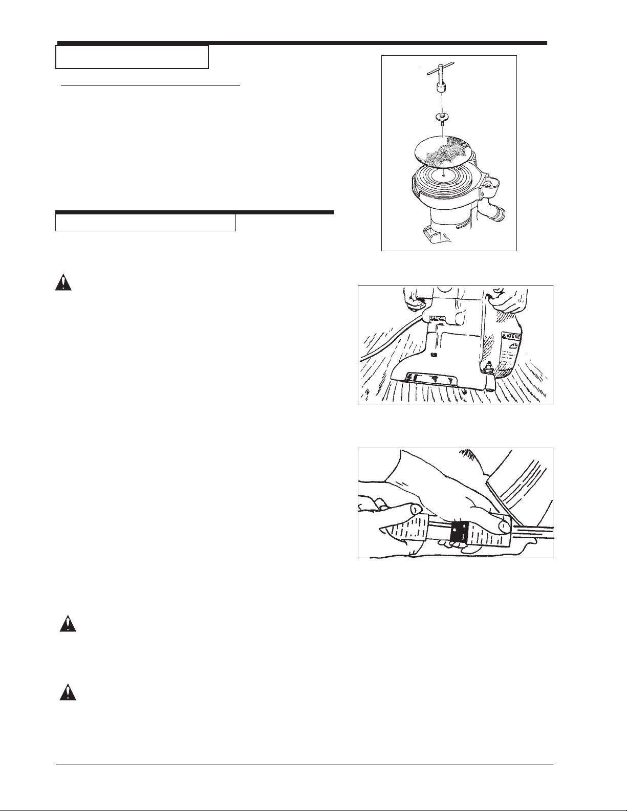
1. Remove screw and abrasive retainer. Center abrasive on
pad and secure with abrasive retainer and screw. (Figure
1)
2. Return machine to upright position and tilt machine back on
casters until it comes to rest on the exhaust bracket.
Machine will be in a reclined position. Do not allow machine to rest on pad especially after use, or compression
set may take place within elastomer on pad. This will
create a flat spot and bounce during use. (Figure 2)
OPERATING INSTRUCTIONS
1. Move machine to the location of your work. Set any
exposed nails with hammer and punch to avoid encounter
with abrasive.
Figure 1
WARNING: Bodily injury could occur if power is applied to the
machine with the power switch already in the "ON"
position. Always check to assure that the power
switch is in the "OFF" position before applying
power to the power cable.
2. Make sure the control switch is in the "Off" position then
connect the supply cable to an appropriately grounded
fused circuit. Connect the supply cable to the motor pigtail.
(Figure 3)
3. With the machine in the reclined position firmly grasp both
handles and flip the control switch to the "ON" position.
(Figure 2.)
4. Gradually lower pad to surface intended for sanding.
Make sure the machine is in motion while the pad is
engaged with the surface to be sanded. You may use
broad circular motion as you sand along the length of
the surface or your may use a combination of forward
and sideward motions. In time you will develop your
own technique to optimize coverage and dust recovery. It
is advisable to not add effort to the pad as this may lead
to "nosing in" or "tipping" which produces grooves or
lines on the surface.
5. When replacing abrasive, emptying the contents of the
dust bag, or sanding operation is completed, return
machine to reclined position, flip control switch to "Off"
then disconnect the motor pigtail from the supply cable.
Figure 2
Figure 3
6. Empty dust bag whenever it becomes 1/3 full.
DANGER: Failure to disconnect the supply cable from
machine whenever servicing, replacing
abrasive, or emptying the dust bag could
result in electrocution or severe injury. Never
leave machine unattended while the supply
cable is connected.
DANGER: Never leave dust bag unattended with
sanding dust in it. Sanding dust can
spontaneously ignite and cause a fire or
explosion. Empty dust bag into a metal
container, clear of any combustibles. Do not
empty content into a fire. Do not overfill dust
bag.
Page 8 Clarke® American Sanders Super 7R Operator's Manual
Page 9
ADJUSTMENT PROCEDURES
Leveling
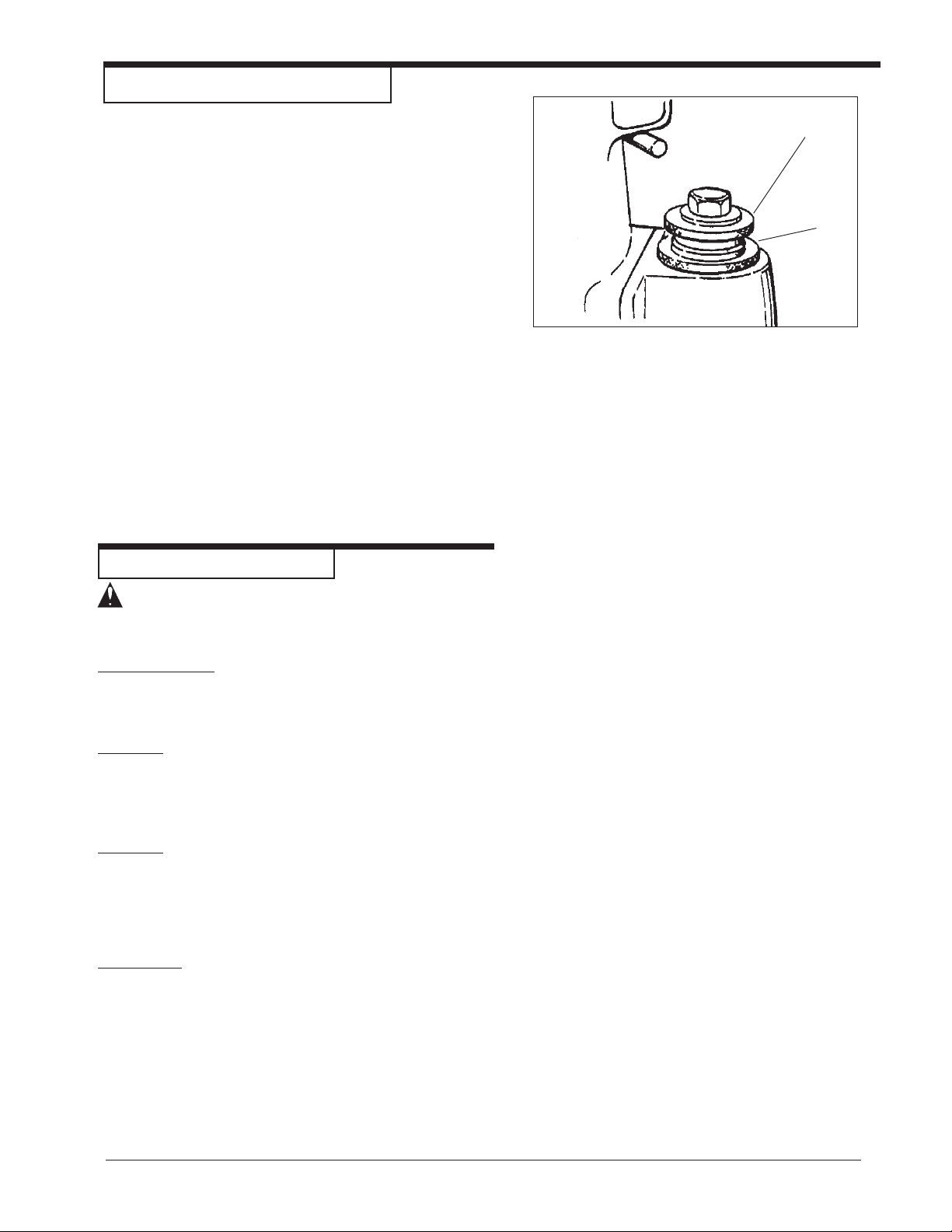
To level machine: Grasp caster adjusting screw "A" with an
appropriate tool (pliers ect.). Using a similar tool, loosen
locknut "B" with a counter clockwise motion. (Figure 4).
Condition - Pad creates ridges on both edges or a "hop" is
experienced: Rotate both adjusting screws equal amounts
clockwise. Tighten locknuts and test on a piece of plywood. Repeat procedure until condition is corrected. We
recommend you not exceed 1/8" rotation for each attempt.
Condition - Pad creates a ridge on the tip of the pad:
Rotate both adjusting screws counter clockwise, tighten
locknuts and test. Repeat procedure until condition is
corrected. Use only 1/8 rotation for each attempt.
Condition - Pad creates a ridge on only one side of the pad:
Either rotate the adjusting screw of the side effected
clockwise or rotate theadjusting screw opposite counterclockwise, depending on whether the ridge terminates
beyond the tip of the pad or prior to it. If it is prior to the
tip, adjust the side effected, otherwise adjust the opposite
side.
A
B
Figure 4
ROUTINE MAINTENANCE
CAUTION: Failure to perform maintenance at
recommended intervals may void
warranty.
Carbon Brushes
Have the carbon brushes replaced at least every 500
hours and more frequently under heavy use.
Dust Bag
Periodically the dust bag should be turned inside out,
shaken vigorously and machine washed in cold water
to prevent pore blockage and loss of dust control.
Bearings
To insure reliable performance, have armature and pad
driver bearings inspected for wear or damage after every
1500 hours. If used heavily, have the bearings replaced
seasonally.
Lubrication
The machine comes fully lubricated. The gears in the
gear box have enough lubrication for approximately six
months of normal operation. Have the lubricant changed
at least every 6 months or more frequently under heavy
use.
Clarke® American Sanders Super 7R Operator's Manual Page 9
Page 10

MAINTENANCE
CAUTION: Maintenance and repairs performed by
unauthorized personnel could result in
damage or injury. Maintenance and
repairs performed by unauthorized
personnel will void your warranty.
Failure to perform maintenance at
recommended intervals may void
warranty.
Carbon Brushes
Inspect all four brushes every 6 months or 250 hours.
Access to the brushes is gained through the front and
back motor vent plugs and under both motor covers (figure
5). Press tab on spring clip assembly in, rotate, then
remove (figure 6).Use needlenose pliers to disconnect the
shunt wire. If any brush has worn to 3/8" in length or
shorter, replace the entire set.
CAUTION: Use only motor brush PN 40818A or
PN 40055A with shunt wire or motor
failure will occur.
When replacing the brushes make sure that the brush
seats against the commutator, the spring rest in the
recess of the brush, and the brush is free to travel. When
returning the switch cover, keep any wires clear of the
commutator and any pinch site.
Figure 5
To Change The Lubricant In The Gearbox
To change the lubricant in the gearbox, follow this procedure:
1.Put the machine upside down on a bench.
2.Align one of the two holes in the rubber pad with one
of the three holes in the rotating wall guard.
3.Align both holes with one of the three screws in the
gear housing cover. Remove the screw from the gear
housing cover. (Figure 7)
4.Align the holes with each of the other two screws,
then remove screws.
CAUTION: Make sure no dust enters the gear box.
Damage will occur to the gear box.
5.Remove the cover from the gear housing.
6.Remove the old lubricant from the gearbox.
7.Add six ounces of American SandersTechnology
lubricant to the gear box.
CAUTION: To prevent damage to the motor, do not
add more than six ounces of lubricant to
the gearbox.
8.Using the three screws removed above, install the
cover on the gear housing.
9.Start the machine and let it run for 15 minutes. A
small amount of excess lubricant should flow out the
vent hole. If none appears it may be necessary to
add additional lubricant.
10.Wipe off excess lubricant and clear vent hole.
Figure 6
Lubricants
Qty Part No.
1Qt. 16610A
1Gal. 16611A
Figure 7
Page 10 Clarke® American Sanders Super 7R Operator's Manual
Page 11

Super 7R
Edger
Section II
Parts and Service Manual
(70895A)
Clarke® American Sanders Super 7R Operator's Manual Page 11
Page 12

Super 7R Edger
Drawing - 11/04
99
16
39
9
38
8
11
18
17
41
47
61
53
69
56
65
62
71
65
65
67
64
66
65
70
72
63
68
54
40
41
57
100
87
1
3
5
14
12
4
37
7
10
47
15
19
52
20
21
22
23
24
25
26
28
30
2
96
32
6
51
29
27
29
34
33
14
36
95
35
7
46
48
49
50
31
73
74
75
76
77
90
78
91
92
93
82
33
75
83
84
85
97
98
58
50
60
79
80
81
94
Page 12 Clarke® American Sanders Super 7R Operator's Manual
Page 13

Super 7R Edger
Parts List - 1 1/04
Ref# Part No. Description Qty
1 962404 Screw - #10-24 x 3 ¼ Ft. St. Mach. 4
2 70487A Plate - Name 1
3 646302 Plate - Dial 1
4 473 94A Switch - Toggle 1
5 302310 Cover, Motor Brush R.H. 1
6 302309 Cover, Motor Brush L.H. 1
7 306802 Plug - Vent 2
8 432 01A Holder Assembly Brush 1
9 408 18A Carbon Brush 115V 4
4005 5A Carbon Brush 240V 4
10 962727 Screw - #8-32 x ½ Pan Head 4
11 962988 Screw - ¼ -20 x 1¼ Pan St. Mach. 1
12 980662 Washer - SH #1224-00 Lock 1
13
14 962545 Screw - #6-32 x 3/8 Ft. St. Type 23 4
15 85 393 A Screw - #10-24 x ¼ Pn. St. Mach. 1
16 962310 Screw - #10-24 x ½ OV 1
17 303602 Guard - Lamp 1
18 46902 A Socket -Assembly 1
19 911113 Light Bulb 115V 1
911116 Light Bulb 240V 1
20 10101B Armature Assembly 115V 1
10110A Armature Assembly 240V 1
21 303004 Fan - Motor 1
22 293403 Gasket - Fan Baffle 1
23 306102 Plate - Exhaust Fan Baffle 1
24 303002 Fan - Vacuum 1
25 307302 Ring - Retaining 1
26 308202 Spacer - Bearing 1
27 297604 Seal - Oil 1
28 407302 Ring - Retaining 1
29 902567 Bearing 2
30 293514 Pinion - Armature 1
31 316804 Plug - Pipe 1/8 1
32 304204 Housing - Gear 1
33 915028 Key 1/8 x 5/8 Woodruff 3
34 980621 Washer, #1108 1
35 962550 Screw, 8-32 x 5/16 1
36 302312 Cover, Motor 1
37 56475A Strain Relief 1
38 50932A Spring brush Holder 4
39 732 8 5 A Label, Warning 1
40 80276A Nut, Slip Joint 2 x 2 1
41 306 13A Washer Seal 2
46 962211 Screw - #10-24 x 2½ Pn. St. Mach. 2
47 980603 Washer - #1110 Shakeproof 7
48 980643 Washer - #10 7/16 Plain 2
49 42820A Field 115 Volt 1
42819A Field 240 Volt 1
50 962454 Screw - ¼-20 x 1 Sc. Cap 2
51 304208 Housing and Guard Assembly 1
20013A Housing, Motor Super7R 1
52 298306 Spring Load 1
Ref# Part No. Description Qty
53 42 234 A Cord Supply 115V 1
4218 2A Cord Supply 240V 1
4000 7A Cord Supply w/AUI-10P 1
54 53 5 4 4 A Bag, Dust 1
56 61 5 64 A Tube, Exhaust 1
57 30 563A Adaptor, 2" Tube x 1½" Hose 1
58 210 77A Adaptor, Exhaust 1
59 293406 Gasket - Exhaust Bracket 1
60 302101 Clamp - Wrench 1
61 962987 Screw - 10-24 x 3/8 Pn. St. Typ. 1
62 987300 Wrench 1
63 962289 Screw - ¼-20 x 3/4 Soc. St. Cap 4
64 857 02A Screw - ¼-20 x 1¾ 2
65 50740A Bearing 8
66 960130 Screw - Caster Adjusting 2
67 920670 Nut - Lock Adjust 2
68 310803 Bracket - Caster Support 2
69 298215 Spacer - Collar 2
70 29 4 04 A Yoke, Edger, Caster 2
71 299704 Roller - Caster 2
72 925592 Pin - ¼ x 1 Spirol 2
73 318303 Spring - Load 1
74 307702 Shaft - Drive Gear 1
75 902550 Bearing 2
76 303502 Gear - Drive 1
77 067304 Ring - Retaining 1
78 302306 Cover - Assembly Gear Housing 1
79 317204 Retainer - Disc Guard 1
80 293616 Guard - Disc 1
81 980088 Washer 2
82 13 20 3 A Assembly - Sanding Pad 1
83 980132 Washer - Disc, Retaining 1
84 960140 Screw - Paper Lock 1
85 925004 Pin - Cotter 1/16 x ½ 1
87 962109 Screw - #10-24 x 5/8 Pn SS 4
90 34 23 2A Gasket - Gear Case Cover 4
91 87 609A Washer Seal 3
92 84 808A Screw, 10-24 x 3/4 3
93 962974 Screw, 6-32 x ½ 4
94 960125 Assembly Screw Lock 1
95 41960A Motor Pigtail 115V 1
41947A Motor Pigtail 240V 1
96 912169 Plug L5-15P (115V) 1
4560 2 A Plug L6-15P (240V) 1
97 911461 Connector L5-15R (115V) 1
4170 8A Connector L6-15R (240V) 1
98 70 17 5A Tag, Warning 1
99 911248 Plug 5-15P (115V) 1
4560 3 A Plug 6-15P (240V) 1
40023A Plug AUI-10P 1
100 122 08A Caster, Assembly 1
NI 31407A Case, Super 7R Edger 1
Accesories Available
NOTE: Assembly 12208A includes parts 64, 65, 70, 71,
& 72.
Clarke® American Sanders Super 7R Operator's Manual Page 13
a 311306 Blade - Disc Cutter 1
b 312904 Eject Disc Cutter 1
c 315604 Mallet 1
d 317004 Punch Center 1
e 317304 Ring Disc Cutter 1
f 762005 Clamp 1
g 920208 Nut - ¼-20 Hex 1
h 962013 Screw ¼-20 x 1¼ R 1
i 962233 Screw ¼-20 x 5/16 S1
312404 Cutter Disc Assembly 1
Page 14

Model Super 7R Edger
Wiring Diagram 11/04
Page 14 Clarke® American Sanders Super 7R Operator's Manual
Page 15

CLARKE PRODUCT SUPPORT BRANCHES
U. S. A. Locations European Locations
CORPO
PRODUCTION FACILITIES
®
Clarke
, Springdale, Arkansas
2100 Highway 265
Springdale, Arkansas 72764
(479) 750-1000
Customer Service - 1-800-253-0367
Technical Service - 1-800-356-7274
American Lincoln®, Bowling Green, Ohio 43402
1100 Haskins Road
SERVICE FACILITIES
Clarke®, Elk Grove, Illinois 60007
2280 Elmhurst Road
(847) 956-7900
Clarke®, Denver, Colorado 80204
1955 West 13th Ave.
(303) 623-4367
Clarke®, Houston, Texas 77040
7215 North Gessner Road
713-937-7717
PRODUCTION FACILITIES
ALTO Danmark A/S, Aalborg
Blytaekkervej 2
DK-9000 Aalborg
+45 72 18 21 00
ALTO Danmark A/S, Hadsund
Industrikvarteret
DK-9560 Hadsund
+45 72 18 21 00
SALES SUBSIDIARIES
Clarke® Canada Ltd., Rexdale Ontario
24 Constellation Ct.
(416) 675-5830
ALTO Overseas Inc., Sydney (Australia)
1B/8 Resolution Drive
Caringbah NSW 2229
+61 2 9524 6122
ALTO Cleaning Systems Asia Pte Ltd., Singapore
No. 17 Link Road
Singapore 619034
+65 268 1006
SERVICE AND SALES FACILITY
American Lincoln® / Clarke, Madison Heights,
Michigan 48071-0158
29815 John R.
(810) 544-6300
American Lincoln® / Clarke, Marietta, Georgia 30066
1455 Canton Road
(770) 973-5225
SALES AND DISTRIBUTION CENTER
Clarke®, Secaucus, NJ 07094
74 Henry Street
(201) 864-5503
Clarke
®
Clarke American Sanders
A.L. Cook
Customer Service Headquarters and Factory
2100 Highway 265
Springdale, Arkansas 72764
(479) 750-1000
Technical Service
1-800-356-7274
ALTO Deutschland GmbH, Bellenberg (Germany)
Guido-Oberdorfer-Straße 2-8
89287 Bellenberg
+49 0180 5 37 37 37
ALTO Cleaning Systems (UK) Ltd., Penrith
Gilwilly Industrial Estate
Penrith
Cumbria CA11 9BN
+44 1768 868 995
ALTO France S.A. Strasbourg
B.P. 44, 4 Place d’Ostwald
F-67036 Strasbourg
Cedex 2
+33 3 8828 8400
ALTO Nederland B.V.
Postbus 65
3370 AB Hardinxveld-Giessendam
The Netherlands
+31 184 677 200
ALTO Sverige AB, Molndal (Sweden)
Aminogatan 18
Box 4029
S-431 04 Molndal
+46 31 706 73 00
ALTO Norge A/S, Oslo (Norway)
Bjornerudveien 24
N-1266
+47 2275 1770
Page 16
Clarke
This Clarke American Sanders Industrial/Commercial Product is warranted to be free from defects in
materials and workmanship under normal use and service for a period of one year from the date of purchase,
when operated and maintained in accordance with Clarke American Sanders's Maintenance and Operations
Instructions.
This warranty is extended only to the original purchaser for use of the product. It does not cover normal
wear parts such as electrical cable or V-belts.
If difficulty develops with the product, you should:
(a). Contact the nearest authorized Clarke American Sanders repair location or contact the Clarke American
Sanders Service Operations Department, 2100 Highway 265, Springdale, Arkansas 72764, for the nearest
authorized Clarke American Sanders repair location. Only these locations are authorized to make repairs to
the product under this warranty .
(b). Return the product to the nearest Clarke American Sanders repair location. Transportation charges to
and from the repair location must be prepaid by the purchaser .
(c). Clarke American Sanders will repair the product and or replace any defective parts without charge within
a reasonable time after receipt of the product.
Clarke American Sanders's liability under this warranty is limited to repair of the product and/or replacement of parts and is given to purchaser in lieu of all other remedies, including INCIDENT AL AND CONSEQUENTIAL DAMAGES.
THERE ARE NO EXPRESS WARRANTIES OTHER THAN THOSE SPECIFIED HEREIN. THERE ARE NO
WARRANTIES WHICH EXTEND BEYOND THE DESCRIPTION OF THE FACE HEREOF. NO WARRANTIES,
INCLUDING BUT NOT LIMITED TO WARRANTY OF MECHANTABILITY, SHALL BE IMPLIED. A warranty
registration card is provided with your Clarke American Sanders product. Return the card to assist Clarke
American Sanders in providing the performance you expect from your new floor machine.
®
American Sanders U. S. W arranty
Clarke
®
, 2100 Highway 265, Springdale, Arkansas 72764
Clarke American Sanders reserves the right to make
changes or improvements to its machine without notice.
Always use genuine Clarke American Sanders Parts for repair.
2100 Highway 265
Springdale, Arkansas, 72764
 Loading...