

Page 1
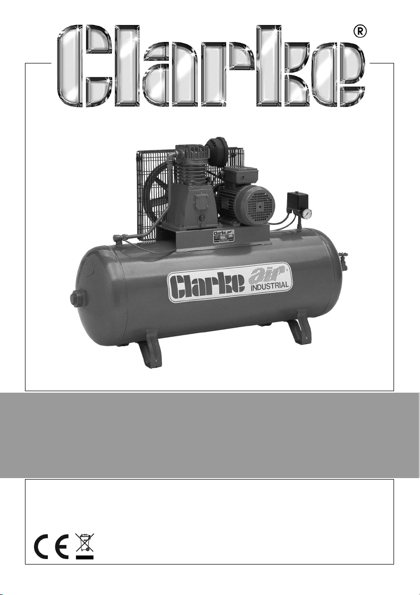
AIR COMPRESSOR
ELECTRIC MOTOR DRIVEN
OPERATION & MAINTENANCE
INSTRUCTIONS
Original Instructions
LS1216
Page 2
INTRODUCTION
Thank you for purchasing this CLARKE compressor which is designed to supply
compressed air to air powered tools for a wide range of applications such as
spraying, sanding, drilling, and cutting.
Before attempting to use this product, please read this manual thoroughly and
follow the instructions carefully. In doing so you will ensure the safe operation
of the compressor.
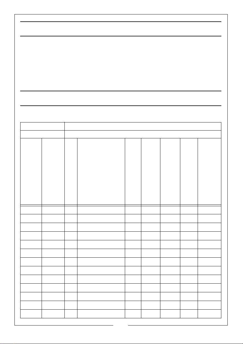
DATA TABLE
This manual covers the following machines
Manufacturer: Clarke International
Type of Machine: Electric Compressor
Machine Model:
SE15 100 PSI 1m 1.28 x 0.40 x 0.81 82 96.5 2.5 dB 99 66 kg
PE15 100 PSI 1m 0.95 x 0.4 x 0.75 84 97.5 2.5 db 100 58 kg
PE16 100 PSI 1m 0.95 x 0.4 x 0.85 80 93.5 2.5 db 96 70 kg
PEH15 100 PSI 1m 1 x 0.46 x 0.86 84 97.5 2.5 db 100 64 kg
PEH16 100 PSI 1m 1 x 0.46 x 0.86 80 93.5 2.5 db 96 76 kg
SE18 100 PSI 1m 1.42 x 0.45 x 0.945 83 98.1 2.5 db 101 102 kg
SE19 100 PSI 1m 1.42 x 0.45 x 0.93 80 96.5 2.5 db 99 89 kg
SE25 100 PSI 1m 1.42 x 0.45 x 1 82 97 2.5 db 100 117 kg
SE26 100 PSI 1m 1.42 x 0.45 x 0.99 81 95.5 2.5 db 98 133 kg
SE29 100 PSI 1m 1.54 x 0.52 x 0.96 87 101.5 2.5 db 104 139 kg
SE36 100 PSI 1m 1.54 x 0.52 x 1.14 83 98 2.5 db 101 140 kg
SE37 100 PSI 1m 1.54 x 0.52 x 1.05 86 101 2.5 db 104 153 kg
SE46 100 PSI 1m 1.54 x 0.52 x 1.2 89 104 2.5 db 107 187 kg
Rated Load:
Measured Distance:
Major Dimensions (m)
Sound pressure:
Mean Value (dB LAeq)
A Weighted Sound Power Level:
Calculated Sound Power Level
K=
Declared Single-Number Noise
Weight
2
Parts & Service: 020 8988 7400 / E-mail: [email protected] or [email protected]
Page 3
GUARANTEE
This product is guaranteed against faulty manufacture for a period of 12
months from the date of purchase. Please keep your receipt which will be
required as proof of purchase.
This guarantee is invalid if the product is found to have been abused or
tampered with in any way, or not used for the purpose for which it was
intended.
Faulty goods should be returned to their place of purchase, no product can
be returned to us without prior permission.
This guarantee does not effect your statutory rights.
ENVIRONMENTAL RECYCLING POLICY
Through purchase of this product, the customer is taking on the
obligation to deal with the WEEE in accordance with the WEEE
regulations in relation to the treatment, recycling & recovery and
environmentally sound disposal of the WEEE.
In effect, this means that this product must not be disposed of with general
household waste. It must be disposed of according to the laws governing
Waste Electrical and Electronic Equipment (WEEE) at a recognised disposal
facility.
NOISE LEVELS
These machines produce noise levels in excess of 70dB(A). Persons working in
the vicinity of the machine must be provided with suitable ear protection.
RESIDUAL RISK
Although this manual contains extensive safety warnings and information on the
safe operation of your compressor, every tool does have certain residual risks
which cannot be compleatly excluded with warnings or safety devices. This
compressor must therfore always be operated with caution.
3
Parts & Service: 020 8988 7400 / E-mail: [email protected] or [email protected]
Page 4

SAFETY PRECAUTIONS
Before using your compressor it is in your own interest to read and pay
attention to the following safety rules:
1. COMPRESSED AIR IS DANGEROUS - Never direct a jet of air at people or
animals.
2. Do not operate your air compressor with any guards removed.
3. Electrical or mechanical repairs should only be carried out by a qualified
electrician/engineer. If you have a problem, contact your local dealer, or our
Service Department on 020 8988 7400
4. Before attempting any repair ensure pressure is expelled from the air receiver
and disconnect from electrical supply.
5. Do not leave pressure in air receiver overnight or when transporting.
6. Do not adjust or tamper with any safety valves. The maximum working pressure
of the compressor is clearly stated on the machine.
7. Exercise caution when transporting the machine to avoid tipping the machine
over.
8. Do not operate in a wet/damp environment.
9. Locate your air compressor on a firm flat surface with AVMs and ensure an
adequate supply of clean air is available to the pump unit.
10. Do not exert any strain on electrical cables and ensure that air hoses are not
tangled or wrapped around machinery etc.
11. The cylinder head and delivery pipes of your compressor become quite hot
during operation. Do not touch. After switching off remember to leave an
adequate cool-down period before touching.
12. Ensure that any equipment/tool used in conjunction with your compressor has
a safe working pressure exceeding the output pressure of the machine.
13. When disconnecting air hoses or other equipment from your compressor
ensure that the air supply is turned off at the machine outlet and expel all
pressurised air from within the air hose and other equipment attached to it.
14. If using your compressor for paint spraying:
• Never spray close to any source of flame or heat.
• Always ensure that the spraying area has adequate fresh air ventilation.
• Hazardous paints require special apparatus (see paint manufacturers
recommendations).
15. Never let people operate the compressor unless they have had the necessary
training.
16. Permanently installed pipework systems should be designed and installed by a
competent engineer.
4
Parts & Service: 020 8988 7400 / E-mail: [email protected] or [email protected]
Page 5
INSTALLATION
Before installing your machine, check that its air output is sufficient for the
equipment to be used. The air output from the compressor must be more than
the volume of air required. We recommend the following:
1. Firm and level site, and the use of floor mountings for stationary
compressors - anti-vibration pads. (Do not bolt machines directly to the
floor).
WARNING: MOVE THE COMPRESSOR ON A PALLET OR USING SLINGS
BENEATH THE RECEIVER NEAR TO THE DOMED ENDS, EMPLOYING A FORK
LIFT TRUCK OR WHEELED GANTRY CRANE. BEWARE OF OFF CENTRE
LOADS. THE WEIGHT OF THE COMPRESSOR IS SHOWN ON THE DATA TABLE
ON PAGE 2.
2. Dust and damp free environment.
3. Adequate ventilation for:-
• Air intake to compressor pump (in order to draw in clean air).
• Cooling to compressor pump, and electric motor.
4. To allow sufficient access for servicing, a minimum clearance of 500mm
must be allowed around the machine.
5. The power cable from the main supply must be large enough to carry the
starting and running load of the electric motor. This is particularly relevant if
the compressor is some distance from the source of supply.
6. Electrical installations should be completed by a qualified electrician.
7. Electrical connection to the mains supply must be via a suitably fused (see
table on page 6) approved plug or isolator (allowing sufficient capacity for
motor starting). If using a circuit breaker, ensure it is motor rated and of
sufficient size to allow for motor starting.
8. Compressors should be connected to mains electricity supply via an earth
leakage protection device (RCD).
5
Parts & Service: 020 8988 7400 / E-mail: [email protected] or [email protected]
Page 6
ELECTRICAL CONNECTIONS
See wiring lable on the power cable.
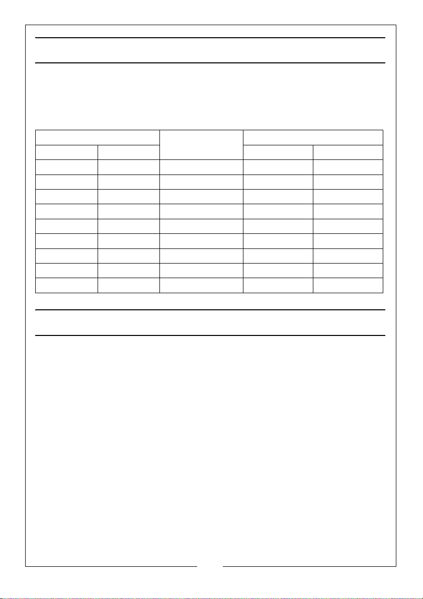
SUGGESTED FUSE RATINGS
MOTOR SIZE SINGLE PHASE
KW HP DOL STAR DELTA
0.75 1.0 13 amp 10 amp
1.1 1.5 13/15 amp 10 amp
1.5 2.0 20 amp 10 amp
1.9 2.5 20 amp
2.2 3.0 30 amp 16 amp
3.0 4.0 40 amp 20 amp
4.0 5.5 50 amp 25 amp
5.5 7.5 30 amp
7.5 10.0 25 amp
MOTOR D.O.L.
THREE PHASE MOTORS 415V
LUBRICATION
Pump: Use Clarke compressor oil, as indicated on machine plate.
6
Parts & Service: 020 8988 7400 / E-mail: [email protected] or [email protected]
Page 7
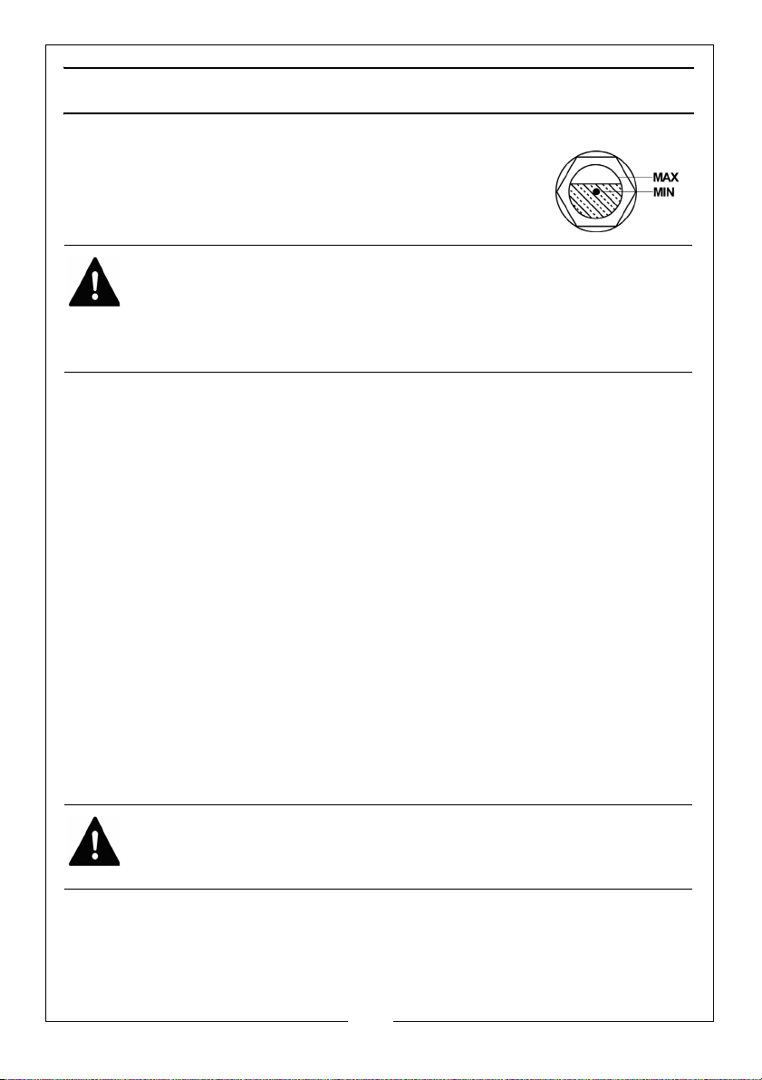
BEFORE STARTING COMPRESSOR, CHECK:-
1. Compressor Pump Oil Level using (a) Dipstick (to level
marked) or (b) sight glass (see fig.1)
2. Automatic Control:- Pressure switch ON/OFF switch is in
the OFF position.
WARNING:
1. BEFORE STARTING COMPRESSOR, OPEN ALL OUTLET VALVES.
2. THE FOLLOWING START AND STOP INSTRUCTIONS MUST BE
FOLLOWED IN THE CORRECT SEQUENCE TO AVOID SERIOUS
DAMAGE TO THE COMPRESSOR/MOTOR.
TO START COMPRESSOR
1. Switch on isolator (mains supply)
2. Switch on pressure switch (lift knob or twist switch). (See “GENERAL
ARRANGEMENT” on page 8., item 22)
3. Check rotation (Flywheel/Fan blows air over pump)
4. Run compressor for 10 minutes with outlet valves open (first time of
operation only).
5. Close valves and check that pressure does not exceed maximum working
pressure (stamped on machine plate), if the pressure exceeds the
maximum working pressure stated, stop the machine (see below), vent the
system and contact the Clarke Service Department.
TO STOP COMPRESSOR
1. Switch off at the pressure switch (Push knob down or turn switch).
2. Isolate from the Mains Supply.
3. Drain air receiver (release drain tap).
WARNING: COMPRESSOR PUMPS, DELIVERY PIPES WILL REMAIN HOT FOR
SOME TIME AFTER USE.
NOTE: When starting compressors up to and including the 3HP models,
an auto bleed valve will operate and air will be heard vent. This is
quite normal and should not cause concern. The valve should
close after several seconds. Should it fail to close, consult your
Clarke dealer.
7
Parts & Service: 020 8988 7400 / E-mail: [email protected] or [email protected]
Page 8
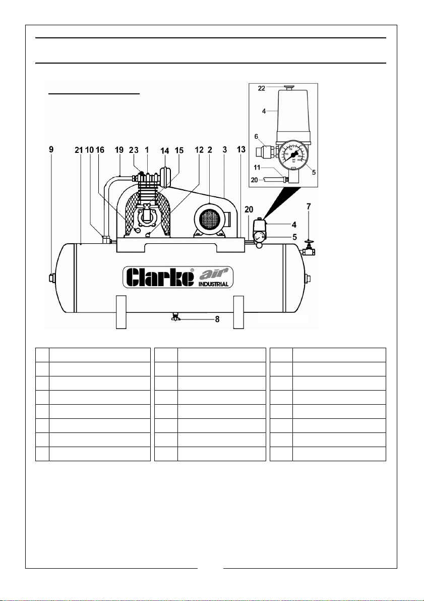
GENERAL ARRANGEMENT
Fig.2
A. STATIONARY
NB: Must be mounted on Anti Vibration Pads
Illustrative
purposes
only
1 Air Compressor Pump 9 Inspection Plug 17 –
2 Electric Motor (or 10 Non-Return Valve 18 –
3 Wire Guard 11 Air Bleed Valve 19 Air Delivery Pipe
4 Pressure Switch 12 Oil Drain Plug 20 Air Bleed Pipe
5 Pressure Gauge 13 Saddle 21 Air Receiver
6 Safety Valve 14 Air Intake Filter 22 On/Off switch
7 Ball Valve 15 Oil Filler/Breather 23 Auto Air Bleed
8 Drain Tap 16 Oil Level Sight Glass
NOTE: On automatic machines (10 H.P). a solenoid valve is fitted to the
delivery pipe.
NOTE: On automatic machines (10 H.P), an Auto Star Delta (ASD) starter
is fitted, ready to be mounted to a wall or panel etc. It is
IMPORTANT to note that NO ADJUSTMENTS should be made to this
component. The ASD should be connected to a 3-phase supply
by a qualified electrician.
8
Parts & Service: 020 8988 7400 / E-mail: [email protected] or [email protected]
Page 9
OUTLET PRESSURE ADJUSTMENTS
Illustrative
purposes
only
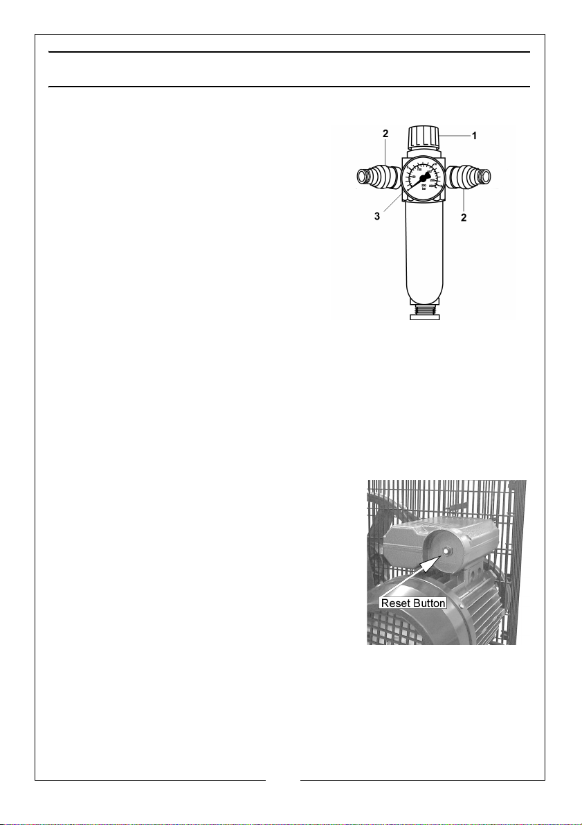
PORTABLE COMPRESSORS
1. Pressure Adjusting Knob
2. Outlet Taps
3. Pressure Gauge
TO ADJUST OUTLET PRESSURE:
To increase pressure - turn knob (1)
clockwise. To decrease pressure - turn
knob (1) anticlockwise.
Outlet taps - slide knurled section (2) away
from body to open, push towards body to
close.
NOTE: Pressure Gauge (3). Pressure shown will differ by approximately 1
bar depending on whether the outlets are open/closed.
STATIONARY COMPRESSORS
These machines are not supplied with the facility to adjust outlet pressure. A
comprehensive range of airline accessories is available from your local
CLARKE stockist.
OVERLOAD BUTTON (SINGLE PHASE ONLY)
The electric motor is fitted with an automatic
overload detector which will stop the motor if an
overload is detected.
If this happens,
1. Switch off at the pressure switch (Push knob
down or turn switch).
• Allow the compressor to cool down for 5-10
minutes.
2. Press the Reset button shown on the right.
3. Switch on pressure switch (lift knob or twist switch).
If the overload trips repeatedly, it may indicate a fault with the compressor, in
this case you should contact the Clarke service department.
OTHER PRODUCTS WITHIN OUR RANGE In addition to Air Compressors from 3–40
cfm, we offer a vast range of air tools and airline equipment. Please ask your
local dealer for details of our range or a copy of our Power Products Catalogue
Parts & Service: 020 8988 7400 / E-mail: [email protected] or [email protected]
9
Page 10
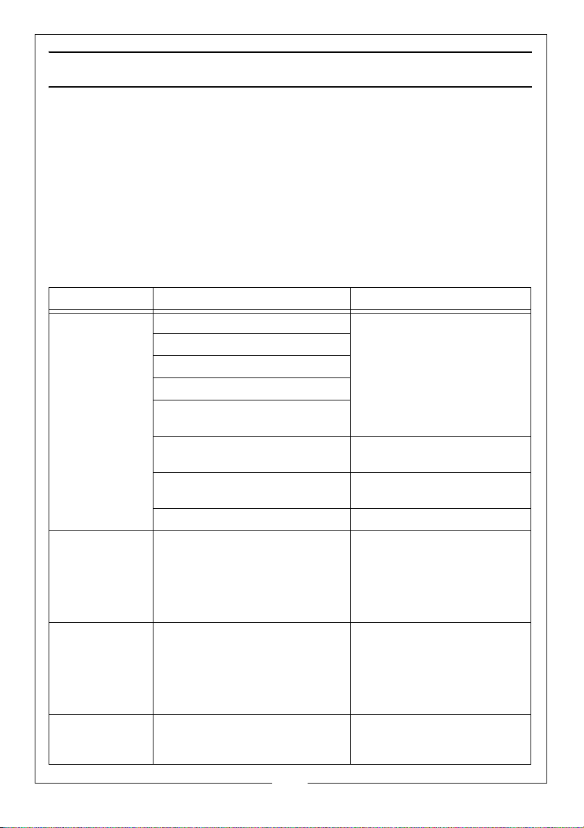
TROUBLESHOOTING CHART
IMPORTANT!
1. Any remedial work that may be required must be carried out by a qualified
electrician/engineer.
2. Disconnect from the mains supply before removing any parts from the
compressor.
3. Empty Air Receiver of Air before dismantling any part of the compressor
unit’s pressure system.
4. If your compressor develops a fault do not use until the fault has been
rectified.
SYMPTOM PROBABLE CAUSE REMEDY
Compressor will
not start
automatically
Bleed valve
under pressure
switch blows
whilst
compressor is
not running
Bleed valve
under pressure
switch blows
whilst
compressor is
running
Compressor unit
will not stop
automatically.
Fault in electrical installation Let an electrician check
Current supply failure.
Voltage drop.
Motor starter faulty.
Motor incorrectly connected or
faulty
Starter overload has tripped
out.
Pressure switch defective. Have pressure switch
Fuse blown. Check fuse rating - replace.
Non-return valve leaking. Clean non-return valve or
Relief valve leaking. Clean relief valve or change
Pressure switch defective. Contact Clarke Service
electrical installation.
Reset by depressing button.
changed by an electrician.
replace.
pressure switch.
10
Parts & Service: 020 8988 7400 / E-mail: [email protected] or [email protected]
Page 11
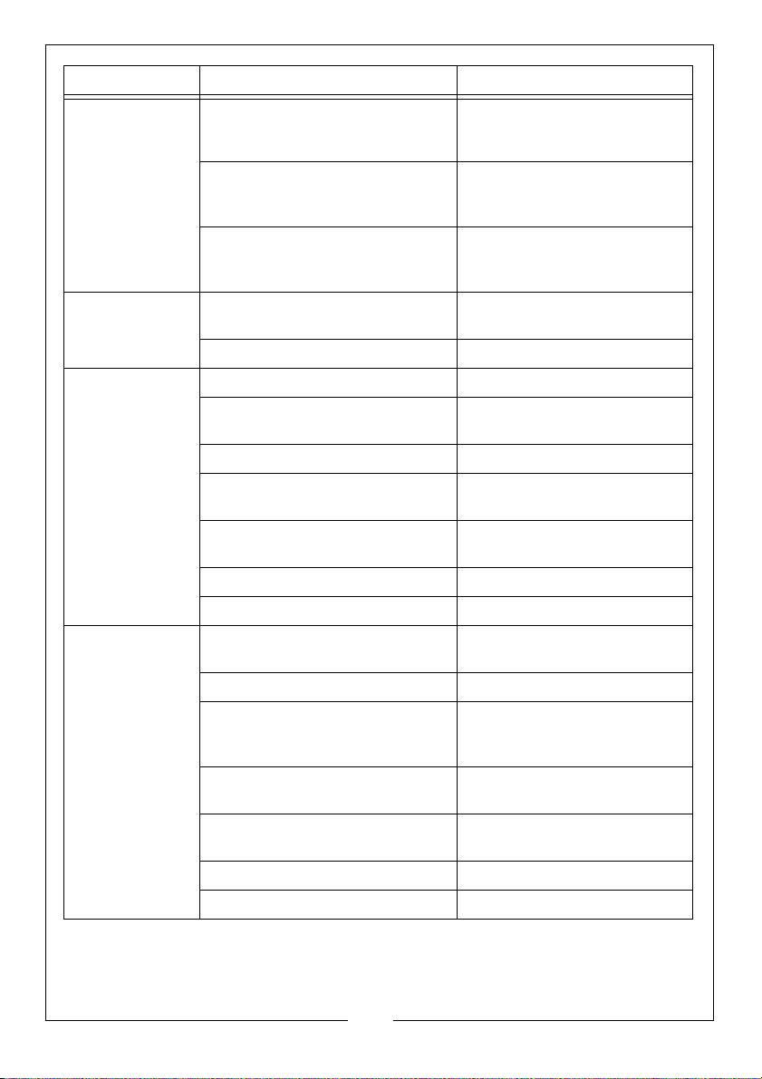
SYMPTOM PROBABLE CAUSE REMEDY
Compressor unit
starts, but stops
again after only
a few
revolutions.
Fuses keep
blowing.
Unusual noise
from
compressor
Compressor’s oil
consumption
rising.
Non-return valve leaking
(compressor unit is on load during
start).
Non-return valve blocked,
possibly frozen up.
Solenoid valve leaking or
defective (only applies to 10 HP
machines and above).
Inadequate size fuse installed. Replace with reference to
Fault in motor. Contact Clarke Service
Bolts loose. Tighten Bolts.
V-Belt flywheel or cooling coil
touching belt guard
Flywheel loose. Tighten flywheel.
Unit installed on an unsuitable
base.
Bearings, piston rings or cylinder
worn.
Valve broken. Contact Clarke Service
Bearings of electric motor worn Contact Clarke Service
Too much oil in compressor. Check oil level 2 or 3 minutes
Leaks around crank case. Contact Clarke Service
Working tem pe ra ture of
compressor too high because of
insufficient cooling.
Unit too small in proportion to air
consumption.
Semi-automatic unit Load too
small.
Cylinder worn Contact Clarke Service
Intake air filter blocked. Clean / Change air filter.
Disconnect from the mains supply
and empty air receiver. Clean
or replace
Thaw non-return valve out
(Unit must be installed in frostfree place).
Contact Clarke Service
chart See page 6.
Find place of contact and
remedy fault.
Move unit to a more solid
base
Contact Clarke Service
after stopping.
Increase ventilation to air
compressor.
Connect supplementary.
Convert to fully automatic
operation.
11
Parts & Service: 020 8988 7400 / E-mail: [email protected] or [email protected]
Page 12
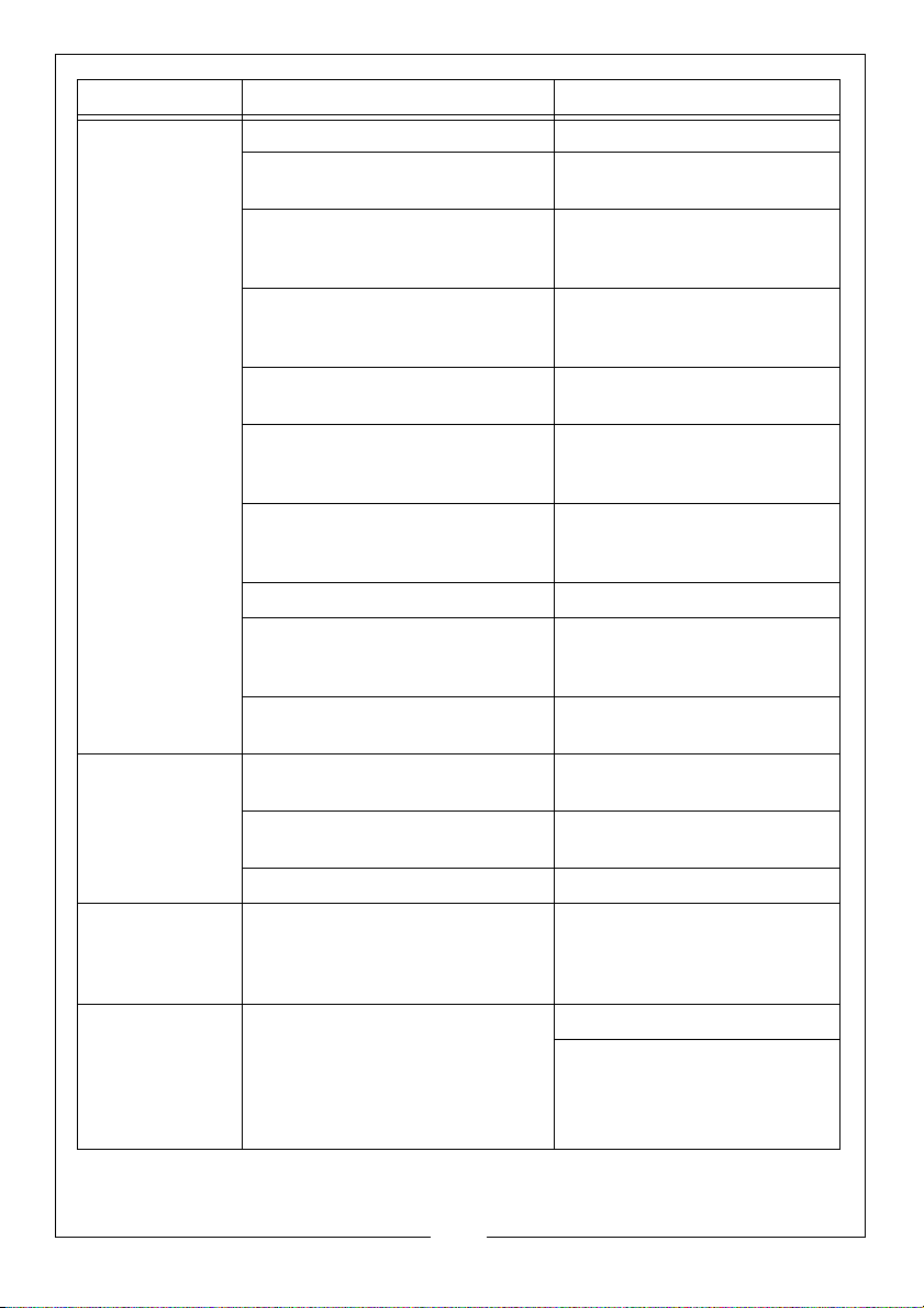
SYMPTOM PROBABLE CAUSE REMEDY
Compressor
runs
continuously
and can’t
attain the
working
pressure
required.
Compressor unit
starts and stops
more frequently
than usual.
Compressor unit
starts when no
air is being
used.
Machine
running but not
pumping air
into the
receiver (10HP
only)
Suction filter blocked. Change filter.
V-belt too slack (not applicable
to direct drive machines).
Leak between compressor block
and air receiver/ leaks in or near
air receiver.
RPM too low because of
incorrectly connected electric
motor.
Valves blocked by dirt, paint, dust
or coked up.
Inspection cover or plug leaking Empty air receiver and
Suction rendered difficult or
impossible at suction intake or the
air being taken in is too warm.
Pressure gauge defective.
Unit too small in relation to air
consumption of connected
equipment
Compressor worn. Have compressor overhauled
Large amount of condensation in
air receiver.
Leaks in control unit or inspection
cover.
Too little pressure differential. Contact Clarke Service
Leaks in pipework system Locate and repair leaks.
Air exhausting from solenoid after
starter has changed direction
from star to delta.
Tighten V-Belt.
Tighten connection and repair
leak or Contact Clarke Service
Contact Clarke Service
Contact Clarke Service
change seal or Contact
Clarke Service
Ensure unobstructed air flow
around the unit.
Install a larger compressor
or replace it.
Drain off condensation AT
LEAST once a week.
Locate leaks (by means of
soapy water) and repair.
Check solenoid valve
Contact Clarke Service
12
Parts & Service: 020 8988 7400 / E-mail: [email protected] or [email protected]
Page 13
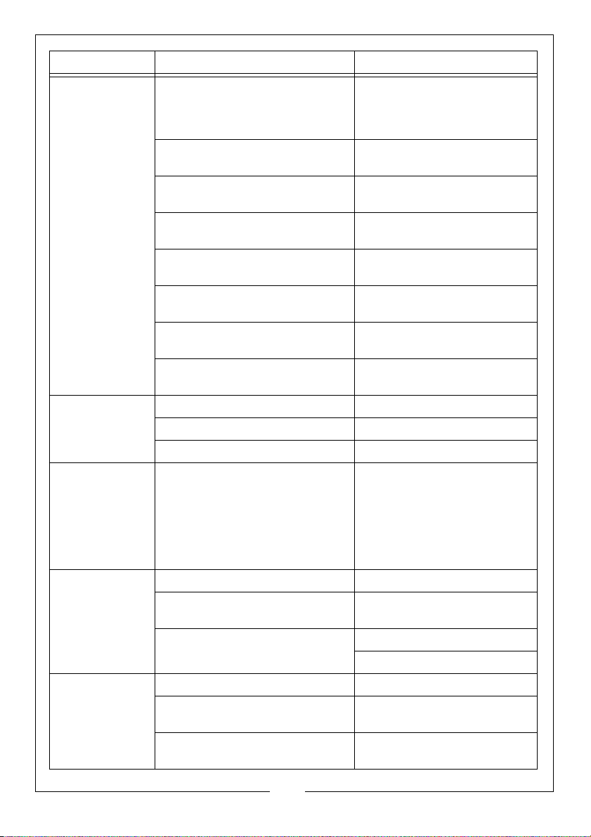
SYMPTOM PROBABLE CAUSE REMEDY
Compressor
becomes too
hot.
Oil in the air
delivered
Condensation
in crank case
(especially in 2stage
compressors).
Insufficient ventilation See that sufficient air is
Oil level too low (check 2 or 3
times after stopping).
Fault in valves (machine not
stopping).
Blown head gasket (machine not
stopping).
Dirt on cooling fins or suction filter. Clean cooling fins and suction
Unit working at too high a
pressure
Non-return valve partly blocked. Clean or thaw out non-return
Compressor being overworked
and running continuously.
Sump over full Reduce oil to correct level
Cylinder worn Contact Clarke Service
Intake air filter blocked Change air filter
Compressor over dimensioned
(operational periods to short in
relation to resting periods).
supplied to flywheel or fan of
compressor and that hot air is
properly vented.
Fill with oil - See page 7.
Contact Clarke Service
Contact Clarke Service
filter.
Contact Clarke Service
valve.
Use a larger compressor
Frequent oil changes
Reduce Cooling of crank case
(e.g. by shielding it from the air
stream).
Contact Clarke Service
Condensation
at outlet points
Electric motor
too hot:
Maximum
temperature
90oC (194oF).
Piping installation is incorrect Consult your local dealer
Compressor is taking in air that is
too warm
Delivery temperature of air from
air receiver is too high
Operational voltage too low Call an electrician
Faults in electrical installation Contact Clarke Service
Cooling fins of electric motor
blocked by dirt
Obtain better fresh air supply
for the compressor.
Use a larger air receiver
Contact Clarke Service
Clean Cooling fins
13
Parts & Service: 020 8988 7400 / E-mail: [email protected] or [email protected]
Page 14
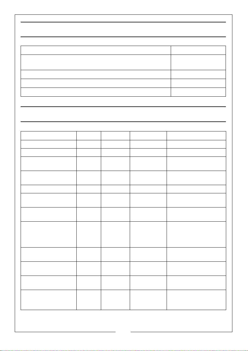
TORQUE VALUES FOR CYLINDER HEAD BOLTS
MODEL NUMBER Torque Value (NM)
SE11C100, SEV11C100, VVE11A150, PEV11C50,
18-22
PEVH11C50, PE11C50, , PPV11ND50, PPVH11ND50
SE16C150, PE16C50, PEH16C50, SE19C200, SE26C200 28-32
SE15C150 35-37
SE25C200, SP27C150, VE25A150, SE18C200, VE18A150 41.2 - 43.2
MAINTENANCE CHART
CHECK LIST DAILY WEEKLY 6 MONTHLY NOTES
Oil level Check Change
Air Receiver Drain
Intake Filter Check /
Clean
Oil breather Check /
Clean
Fan and cooling fins Clean
Inlet and outlet
valves
Non Return Valve Clean Replace if
worn
Belt Tension Check /
Adjust /
Replace if
worn
Big end bearings Check If worn Contact Clarke
Main bearings Check If worn Contact Clarke
Piston Rings If worn Contact Clarke
Cylinder head bolts Check
Torque
settings
Replace if necessary
If worn Contact Clarke
Service department
Does not apply to
direct drive
Service department
Service department
Service department
See above for details.
14
Parts & Service: 020 8988 7400 / E-mail: [email protected] or [email protected]
Page 15
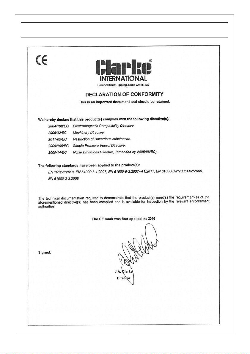
DECLARATION OF CONFORMITY
15
Parts & Service: 020 8988 7400 / E-mail: [email protected] or [email protected]
Page 16
 Loading...