

Page 1
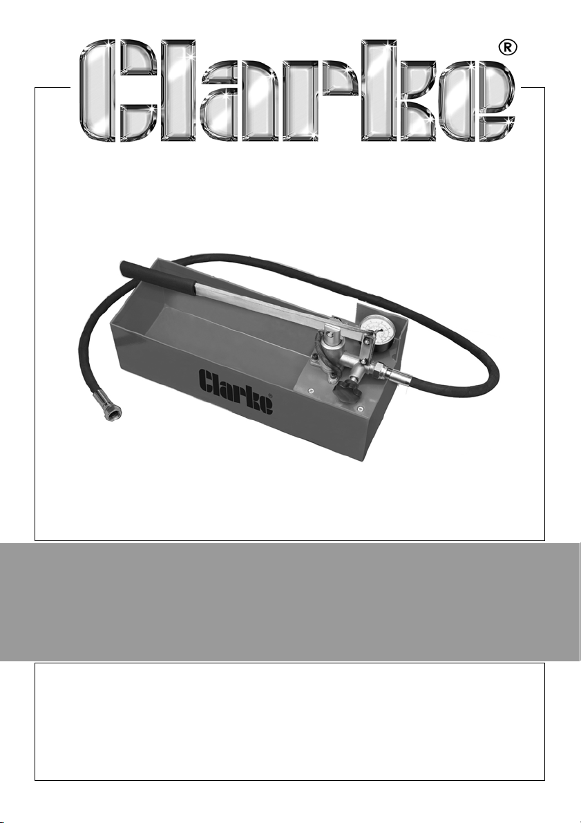
PRESSURE TEST PUMP
MODEL NO: PTP100
PART NO: 5060205
USER INSTRUCTIONS
ORIGINAL INSTRUCTIONS
GC0324 - Rev 3
Page 2
INTRODUCTION
Thank you for purchasing this CLARKE Pressure Testing Pump.
Before attempting to use the product it is essential that you read this manual
thoroughly and carefully follow all instructions given. In doing so you will ensure
the safety of yourself and that of others around you and you can also look
forward to the product giving you long and satisfactory service.
Please keep these instructions in a safe place for future reference.
SPECIFICATION
Dimensions (D x W x H) 528 x 220 x 320 mm
Weight 7 kg
Reservoir capacity 10 L
Pressure 50 bar / 5 MPa / 725 psi
Stroke volume
Gauge max 60 bar (870 psi)
GUARANTEE
This product is guaranteed against faulty manufacture for a period of 12
months from the date of purchase. Please keep your receipt which will be
required as proof of purchase.
This guarantee is invalid if the product is found to have been abused or
tampered with in any way, or not used for the purpose for which it was
intended.
Faulty goods should be returned to their place of purchase, no product can
be returned to us without prior permission.
This guarantee does not effect your statutory rights.
40 cm
3
ENVIRONMENTAL RECYCLING POLICY
Do not dispose of this product with general household waste. All tools,
accessories and packaging should be sorted, taken to a recycling centre and
disposed of appropriately.
2
Parts & Service: 020 8988 7400 / E-mail: [email protected] or [email protected]
Page 3
OVERVIEW
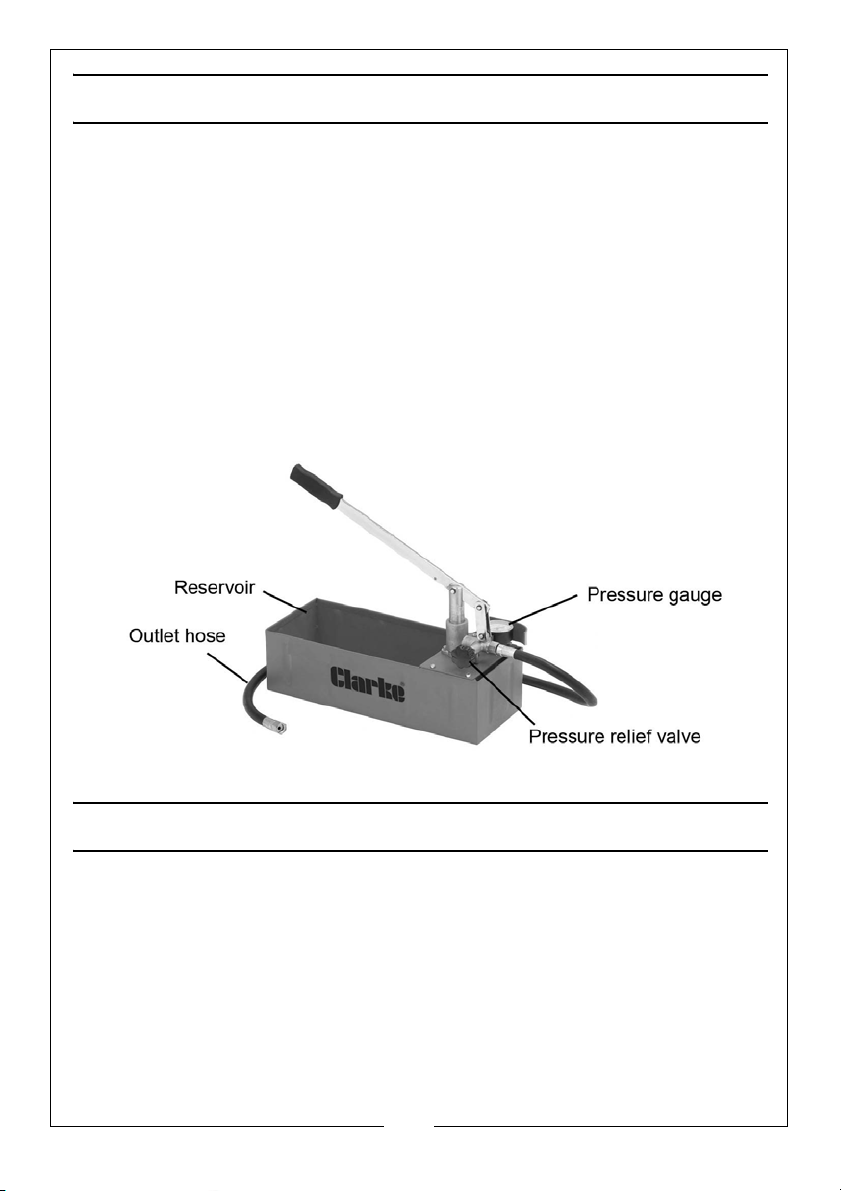
This Pressure Testing Pump is primarily intended for the pressure testing of new
heating installations prior to the connection to the boiler and for fault-finding
of leaks and identifying air ingress problems on existing systems.
When correctly connected to a pipeline/radiator network or complete central
heating system, this hand operated unit is used to build up the required
hydraulic pressure. The reservoir incorporates a filter to prevent dirt entering
the system under test and the gauge is shielded to prevent damage.
It may not be suitable for testing domestic low pressure domestic heating
systems which typically operate between 1.0 to 2.5 bar.
It can also be used for quick and exact pressure testing of installations such as
compressed air and refrigeration systems and small bore pipelines. However, it
is unsuitable for testing gas systems since liquid must be used.
PARTS SUPPLIED
When unpacking, check for damage and /or shortages etc. Any found should
be reported to your CLARKE dealer where the pump was originally purchased.
This Pressure testing pump should include the following:
• 1 x Pressure testing pump assembly
• 1 x Locking pin & chain
• 2 x Sealing washers (O-rings)
• 1 x High pressure hose
3
Parts & Service: 020 8988 7400 / E-mail: [email protected] or [email protected]
Page 4
GENERAL SAFETY RULES
WARNING: AS WITH ALL EQUIPMENT, THERE ARE CERTAIN HAZARDS
INVOLVED WITH THE USE AND OPERATION OF THIS PRODUCT. EXERCISING
CAUTION WILL REDUCE THE RISK OF PERSONAL INJURY.
1. ALWAYS thoroughly familiarise yourself with this product and its operation,
and follow all instructions in this manual.
2. ALWAYS ensure that the pump is properly positioned where necessary to
prevent it from moving during operation, and that the immediate area
surrounding the pump is kept clear.
3. ALWAYS use only replacement parts supplied by the manufacturer. The use
of non standard parts could be hazardous.
4. ALWAYS ensure that any residual pressure has been relieved before
performing any maintenance.
5. ALWAYS use only piping, hose and fittings rated equal to or greater than the
maximum PSI rating of the pump.
6. ALWAYS maintain the equipment in good /clean condition for the best/
safest performance.
7. ALWAYS wear eye protection when working with pressurised systems.
8. ALWAYS return any systems that has been sealed off for testing to their
original state before the system can be used again.
9. ALWAYS wash your hands thoroughly after handling used oil.
10. NEVER exceed the recommended testing pressure for any water heating
system or component within that system.
11. NEVER use this pressure tester for tasks it is not designed to perform.
12. NEVER use this product if it is damaged.
13. ALWAYS establish the correct testing pressure for the pipework/installation
to be tested before attempting to pressurise the system.
14. NEVER allow children to use this product.
15. NEVER attempt any repairs to this appliance.
16. NEVER throw away used oil with domestic refuse or flush down a sink or
drain. Collect any old oil in a leakproof container and take it to you local
waste disposal site.
17. If necessary, have the pump repaired by a qualified person using identical
replacement parts to ensure that the safety of the product is maintained.
4
Parts & Service: 020 8988 7400 / E-mail: [email protected] or [email protected]
Page 5
USING THE PRESSURE TEST PUMP
POINTS TO CONSIDER
1. If you are not a trained plumber or heating engineer, seek professional
guidance on the correct use of this equipment in conjunction with the
system to be tested.
2. Establish the correct test pressure for the installation to be tested by
referring to the system specification and /or the manufacturer’s
recommendations. Given that each pump stroke can produce approx 20
bar of pressure, take care not to over-pressurise the system under test.
3. Ensure the heating system is fully OFF before commencing testing.
4. Any system to be tested must be fully sealed off in order for the test
pressure to build up. When testing is finished, the system must be returned
to its original design state before it can be used again.
5. If the system includes pressure relief valves, these must be temporarily
disabled if the system is to be tested at more than their pre-set relief
pressure. After testing, the pressure relief valves must be re-activated.
6. The system to be tested must be fully filled with water throughout and the
test pressure built up.
BEFORE USE
1. Check the condition of the hose and ensure all connections are tight and
secure. Remove the locking pin to allow full movement of the arm/pivot
assembly.
2. Connect the pressure hose to the pump outlet and the other end to the
system to be tested. A suitable point on the system will need to be chosen
and if necessary, an adaptor used to connect the pump outlet hose to the
fluid system.
CAUTION: NEVER EXCEED THE RECOMMENDED TESTING PRESSURE FOR
ANY WATER HEATING SYSTEM OR COMPONENT WITHIN THAT SYSTEM.
3. Ensure there is sufficient clean liquid in the reservoir to cover the inlet pipe
and then close the pressure relief valve.
4. Pump the handle until the pressure gauge indicates the desired pressure
has been reached. If the required pressure is exceeded, reduce it by
twisting the release valve as required. Allow the unit to stabilise for 15-30
seconds.
5
Parts & Service: 020 8988 7400 / E-mail: [email protected] or [email protected]
Page 6
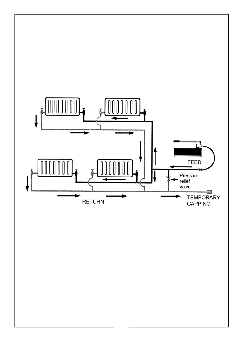
5. If the system is free from leaks, the pressure shown on the gauge will not
drop during the test period. If the pressure is being lost, there is a leak in the
system and a visual inspection should be made to locate the leak.
6. After testing, open the relief valve to release all pressure and allow water to
flow back into the reservoir before disconnecting the pump from the
tested system and re-sealing the point of connection.
7. Where the system has been temporarily sealed for testing, ensure the
system is returned to its original condition.
TYPICAL SYSTEM LAYOUT
6
Parts & Service: 020 8988 7400 / E-mail: [email protected] or [email protected]
Page 7
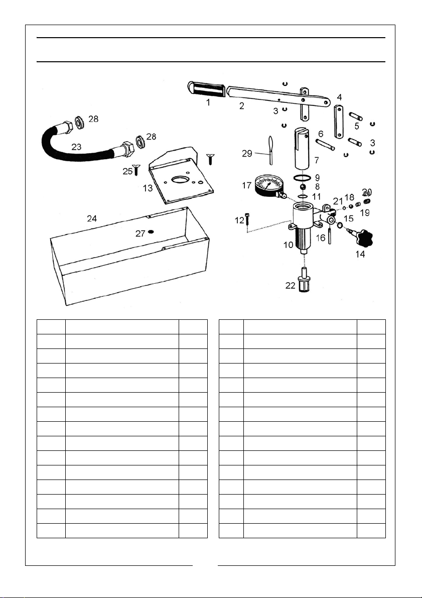
COMPONENT PARTS
No Description Qty No Description Qty
1 Handle grip 1 15 O-ring seal 1
2 Handle 1 16 Connecting tube 1
3 Circlip 6 17 Pressure gauge 1
4 Drop arm 2 18 Steel ball 1
5 Spindle 2 19 Spring 1
6 Axle 1 20 Screw plug 1
7 Piston 1 21 O-ring seal 1
8 Steel ball 1 22 Oil filter 1
9 Airtight gasket 1 23 Oil hose 1
10 Casting body 1 24 Reservoir 1
11 Airtight gasket 1 25 M6 x 16 screw 5
12 M6 x 20 screw 1 26 Pin and chain 1
13 Cover plate 5 27 Nut 7
14 Relief valve 1 28 O-ring 2
7
Parts & Service: 020 8988 7400 / E-mail: [email protected] or [email protected]
Page 8

 Loading...