

Page 1
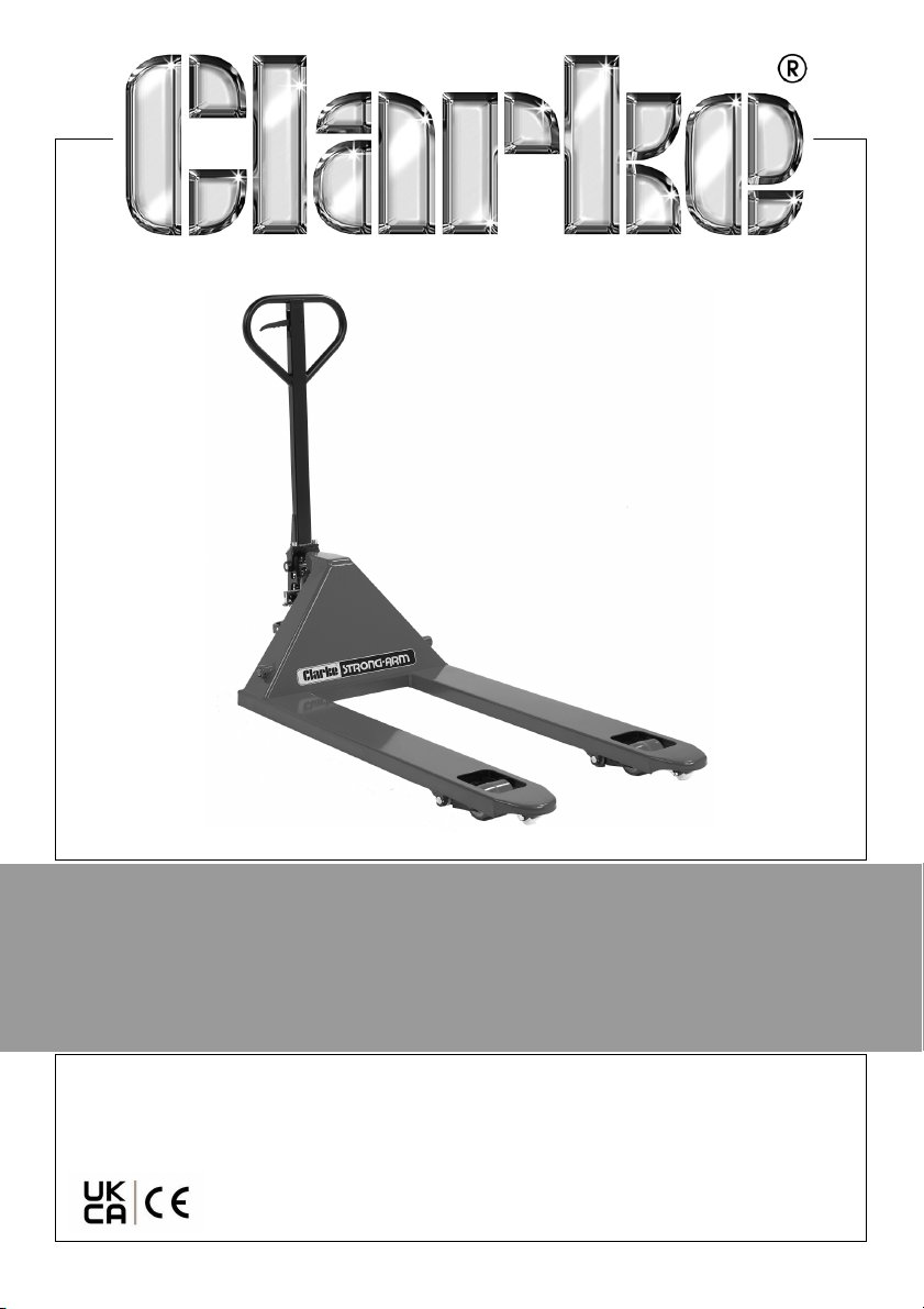
HYDRAULIC PALLET TRUCK
MODEL NO: PT550BD & PT685BD
PART NO: 7631716 & 7631721
OPERATION & MAINTENANCE
INSTRUCTIONS
ORIGINAL INSTRUCTIONS GC1122
Page 2
INTRODUCTION
Thank you for purchasing this CLARKE Hydraulic Pallet Truck designed to lift
and transport the rated load on industrial pallets.
Before attempting to use this product, please read this manual thoroughly and
follow the instructions carefully. In doing so you will ensure the safety of yourself
and that of others around you and you can look forward to your purchase
giving you long and satisfactory service.
Keep these instructions safe for future reference.
INTENDED USE
The operator / operating company has to ensure the correct use and that this
pallet truck is used only by staff who are trained and authorized to use it.
PRODUCT SPECIFICATION
PT685BD PT550BD
Part No 7631721 7631716
Roller layout/type Double/PU Double/PU
Width to outside of forks 685 mm 550 mm
Fork Length 1220 mm 1150 mm
Gap between forks. 365 mm 230 mm
Fork height lowered 85mm 85mm
Maximum Capacity 2500 kg 2500 kg
Dims (L x W x H) mm 1630 x 685 x 1214 1543 x 550 x 1214
Weight 68 kg 59.5 kg
Turning radius (mm) 1276 1276
Max lifting height (mm) 195 195
Lowering speed 0.08m/s 0.08m/s
Oil capacity 250 ml 250 ml
2
Parts & Service: 020 8988 7400 / E-mail: [email protected] or [email protected]
Page 3

SAFETY INSTRUCTIONS
WARNING: THE TRUCK HAS TO BE USED ON SUBSTANTIALLY FIRM,
SMOOTH, LEVEL AND PREPARED SURFACES. THE LOAD MUST BE PLACED
CENTRALLY ON THE FORKS.
The operator should read all warning signs and instructions here and on the
pallet truck before use.
1. Examine the condition of the pallet truck before use, with particular
attention to the wheels, handle, forks and lift/lower controls. DO NOT use
the pallet truck if any defects are found.
2. DO NOT operate a hand pallet truck unless you are familiar with it and
have been trained or authorized to do so.
3. DO NOT make any changes or modifications to the pallet truck.
4. DO NOT use if the wheels or rollers are damaged. Have them replaced
immediately.
5. Keep the work area tidy and well lit.
6. Keep children and bystanders away from the work area.
7. DO NOT exceed the capacity of the pallet truck. Refer to the labelling on
the pallet truck and the Product Specification section in this manual,
8. DO NOT use on rough terrain. The pallet truck is designed for use on smooth
flooring only.
9. DO NOT use the pallet truck on a gradient if the load is too heavy to be
easily handled by the operator. The pallet truck must not be used by
anyone not capable of handling the full weight of the truck when loaded.
10. Watch for differences in the floor levels when moving the truck. The load
may overbalance or the truck could become uncontrollable.
11. DO NOT let the pallet truck come into direct contact with food.
12. DO NOT use the truck in explosive atmospheres.
13. The operator must wear safety shoes and gloves.
14. DO NOT allow personnel other than the operator to stand in front of or
behind the truck when it is moving or lifting/lowering.
15. DO NOT put your foot in front of rolling wheels. Injury could result.
16. DO NOT use the pallet truck as a jack.
17. Ensure nothing is beneath the pallet truck forks prior to lowering, especially
anyone’s feet.
3
Parts & Service: 020 8988 7400 / E-mail: [email protected] or [email protected]
Page 4
18. Load the pallet truck evenly with the centre of gravity of the load above
the centre of the forks. DO NOT move unstable or loosely stacked loads.
Use extra care when moving long, tall or wide loads which impair your
view.
19. Keep watching the load and stop if the load becomes unstable.
20. When not in use, always make sure that the truck is stored where it is not a
danger to others. DO NOT leave the truck on a gradient without first
securely chocking the wheels.
21. Carry out maintenance work according to the “Care & Maintenance” on
page 9.
22. This truck is not designed to be water resistant, therefore use it in a dry
environment.
ENVIRONMENTAL PROTECTION
DO NOT dispose of this product or its packaging with general household
waste. All tools, accessories and packaging should be sorted, taken to a
recycling centre and disposed of appropriately.
To avoid pollution due to oil leakage the user should provide some absorbent
materials to capture any escape of oil during refilling of the hydraulic
mechanism. Such materials should then be disposed of appropriately.
If disposing of this product or any damaged components, do not dispose of
with general waste. This product contains valuable raw materials. Metal
products should be taken to your local civic amenity site for recycling of metal
products.
GUARANTEE
This product is guaranteed against faulty manufacture for a period of 12
months from the date of purchase. Please keep your receipt which will be
required as proof of purchase.
This guarantee is invalid if the product is found to have been abused or
tampered with in any way, or not used for the purpose for which it was
intended.
Faulty goods should be returned to their place of purchase, no product can
be returned to us without prior permission.
This guarantee does not effect your statutory rights.
4
Parts & Service: 020 8988 7400 / E-mail: [email protected] or [email protected]
Page 5
ASSEMBLY
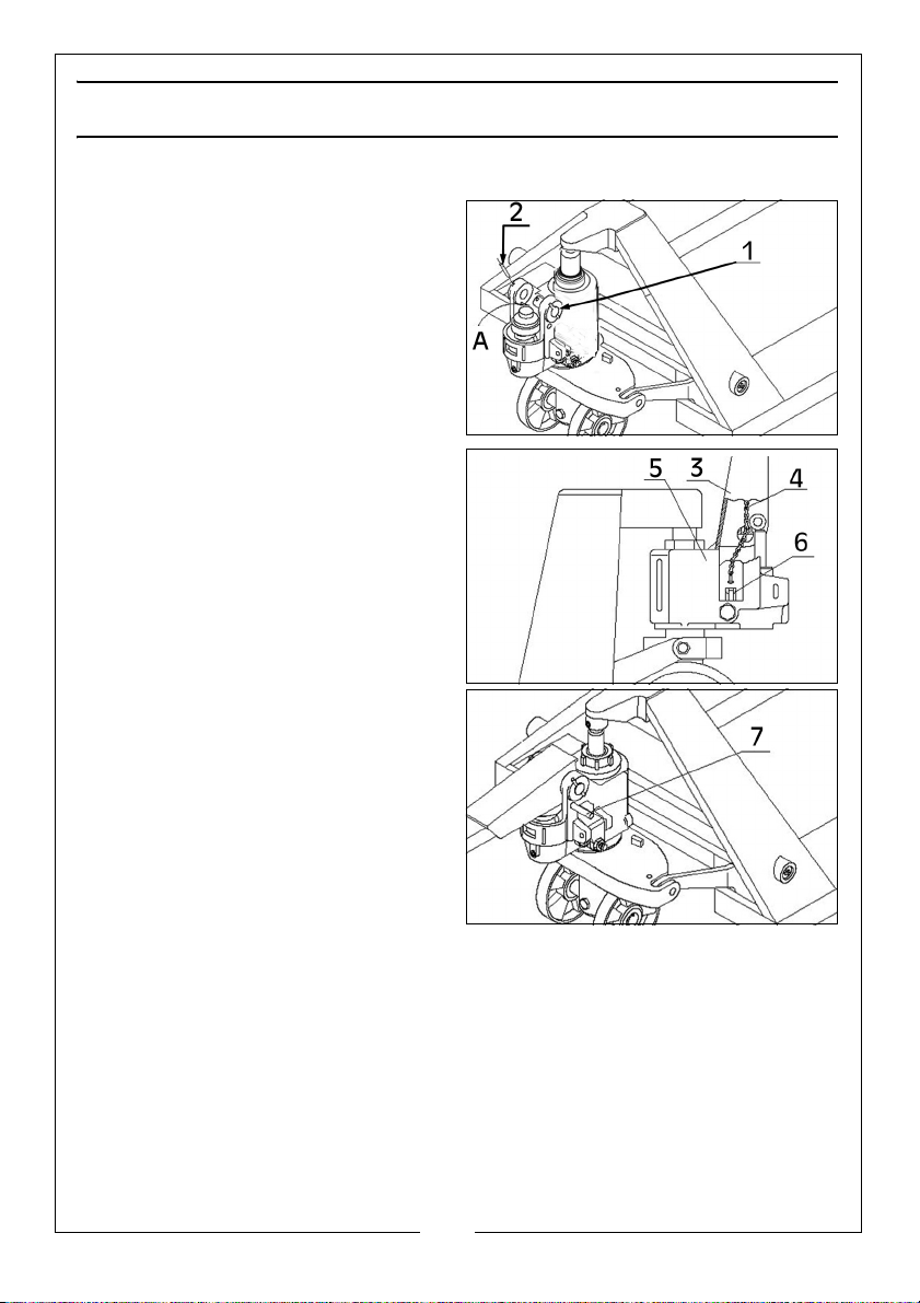
After unpacking it is necessary to attach the handle assembly as follows:
1. Withdraw the hinge pin (1) from
the truck frame.
2. Take the handle assembly and
lower the end of the chain
through the hole in the pump
body so that it emerges at the
bottom of the housing.
3. Insert the hinge pin through the
handle and frame to connect the
handle to the truck and secure
the hinge with the cotter pins at
each end.
4. Take the end of the chain and
lead it past the hinge pin and
engage it with the actuating lever
(6).
5. Move the handle assembly to the
level position and remove the
travel pin (7). Store it safely for
future use.
5
Parts & Service: 020 8988 7400 / E-mail: [email protected] or [email protected]
Page 6
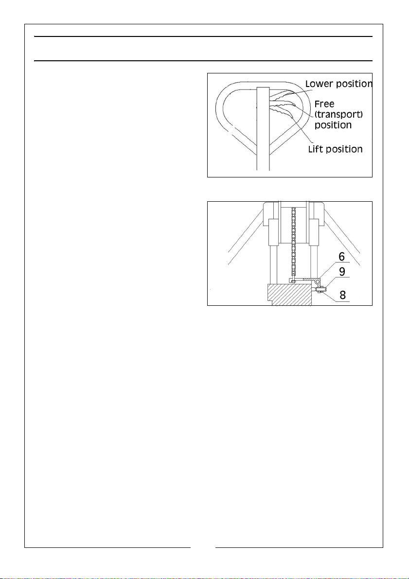
ADJUSTMENT
The control lever has three positions
shown and indicated by the label on
the handle.
• With the lever pulled to the
upper position, the forks will
lower.
• The middle position allows the
load to be transported.
• The lower position will cause
the forks to lift when the handle is pumped.
The screw (9) is used to adjust the
range of movement of the handle
relative to the hydraulic pump.
Raise and lower the handle to make
the forks lift up.
1. If the truck drops immediately
after it is raised, turn the screw (9)
in a counter-clockwise direction
Test again to see if the truck lifts
normally.
2. If the truck fails to lower after being raised, turn the screw clockwise.
The locking nut (8) is used to secure the mechanism once the correct setting is
achieved.
6
Parts & Service: 020 8988 7400 / E-mail: [email protected] or [email protected]
Page 7
OPERATING INSTRUCTIONS
BEFORE USE
Daily inspection is advisable to find any defect of the pallet truck. Check the
following points before operation.
• Visually check for structural damage and listen for any unusual noise or
binding of the lifting mechanism.
• Check if there is any oil leakage.
• Raise/lower the forks to check for vertical creep of the lifting
mechanism.
• Check for any damage to the wheels and ensure they rotate smoothly.
• Check that all the bolts and nuts are tight.
• Verify that all warning labels are in place.
WARNING: DO NOT USE THE PALLET TRUCK IF ANY DEFECT IS FOUND.
LIFTING
1. Check that the load does not exceed the rated capacity of the truck.
2. Roll the pallet truck with its forks slowly under the pallet/load until the back
end of the fork rests against the load.
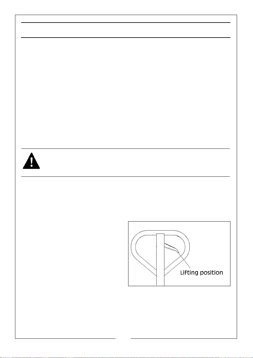
3. Move the operating lever down to
the ‘Lifting’ position. Lift the load
by moving the handle assembly
up and down.
• The load must be evenly
distributed across both forks.
• DO NOT OVERLOAD.
MOVING
1. Ensure the control lever is in its middle (transport) position.
2. Move the truck using the handle assembly.
3. Do not operate the truck on a slope.
4. Watch for differences in the floor level when moving the pallet truck.
7
Parts & Service: 020 8988 7400 / E-mail: [email protected] or [email protected]
Page 8
5. Make sure that the load is stable.
6. If the pallet truck is moving, DO NOT turn the handle at a right angle to stop
the pallet truck.
LOWERING
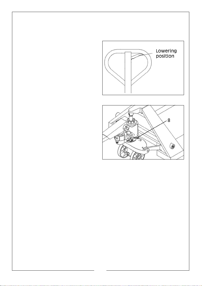
1. Lower the load by moving the
operating lever up to the lowering
position carefully.
• By releasing the lever, the
lowering movement will stop.
• Alternatively, use the foot
pedal (8) to lower the load,
especially where operating
space is restricted.
2. Ensure there is adequate
clearance behind you when
withdrawing the forks from the
pallet.
3. DO NOT put your foot or hand
under the lifting components.
PARKING
When parking the pallet truck, lower
the forks to the lowest position and
park on smooth, level ground where it is not an obstruction. If the ground is not
flat, chock the wheels to stop it moving.
MALFUNCTIONS
If there is any malfunction stop using the truck until it is repaired by your local
CLARKE dealer.
8
Parts & Service: 020 8988 7400 / E-mail: [email protected] or [email protected]
Page 9
CARE & MAINTENANCE
Whilst the pallet truck requires very little maintenance, the following care can
be expected.
PURGING AIR FROM THE HYDRAULIC SYSTEM
If the pallet truck has been
transported over any distance or has
been overturned at any time, air may
have entered the hydraulic system.
This will make it impossible to raise the
forks under load.
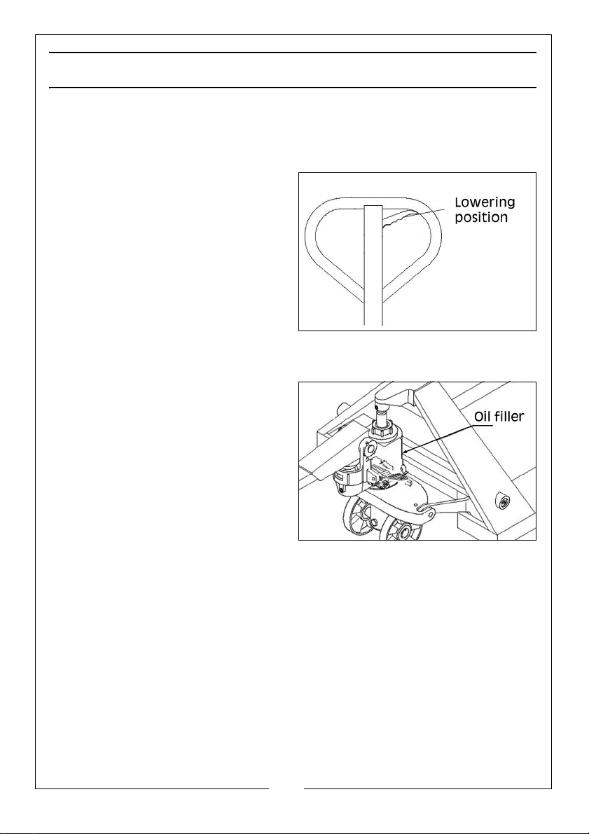
1. Hold the control handle in the
‘lower’ position.
2. Move the handle up and down
several times.
CHECKING THE OIL
1. Check for any oil leaks and top up
if necessary at the filler plug.
• The capacity is approximately
0.25 litre.
• The recommended type is L-
Hydraulic 32 oil, provided the
truck is not to be used outside
the temperature range of -20°C
to +40°C.
9
Parts & Service: 020 8988 7400 / E-mail: [email protected] or [email protected]
Page 10
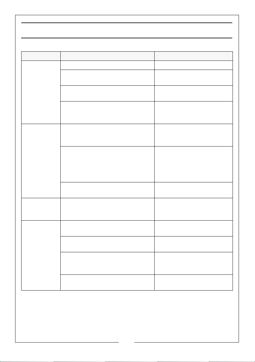
TROUBLESHOOTING
PROBLEM CAUSE ACTION
The forks
cannot be
raised to
the max
height
The forks
cannot be
lowered
Oil l leaks
from the
ram
The forks
lower
on their
own.
Hydraulic oil is low Top up oil.
The oil is contaminated with
moisture.
The chain adjustment for the
operating lever is incorrect
Air in the hydraulic system. Purge air from the
The piston rod is deformed
resulting from load slanting to
one side or over loading.
The fork was kept in the raised
position for long time with the
piston rod exposed to dampness
which caused rusting and
jamming of the rod.
The chain adjustment for the
operating lever is incorrect
Oil seals are worn or damaged. Replace with the new one
Impurities in the oil cause the
release valve to remain open.
Leaks in the hydraulic system. Return to CLARKE dealer
Air in the hydraulic system. Purge air from the
The chain adjustment for the
operating lever is incorrect
Change the oil.
See page 6.
hydraulic system. See
page 9.
Replace the piston rod or
return to CLARKE dealer
for overhaul.
Keep the fork in the lowest
position when not in use
and lubricate the piston
rod.
See page 6.
or return to CLARKE dealer
for overhaul.
Replace with the new oil.
for overhaul.
hydraulic system. See
page 9.
See page 6.
Do not attempt to repair the pallet truck unless you are trained or authorized
to do so.
10
Parts & Service: 020 8988 7400 / E-mail: [email protected] or [email protected]
Page 11
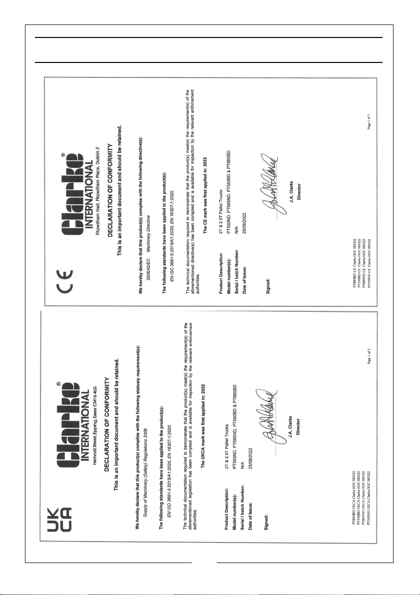
DECLARATIONS OF CONFORMITY
11
Parts & Service: 020 8988 7400 / E-mail: [email protected] or [email protected]
Page 12
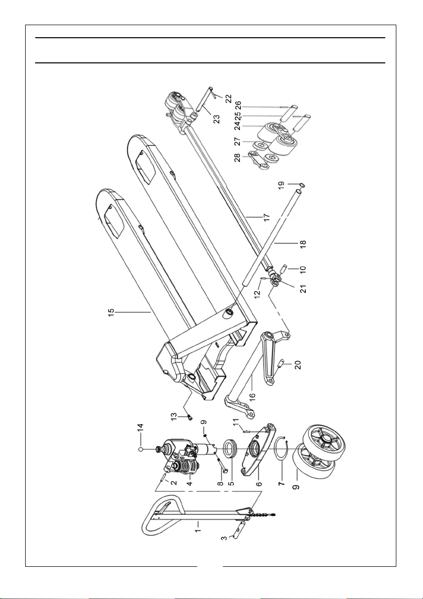
COMPONENT PARTS - FORKS & FRAME
12
Parts & Service: 020 8988 7400 / E-mail: [email protected] or [email protected]
Page 13
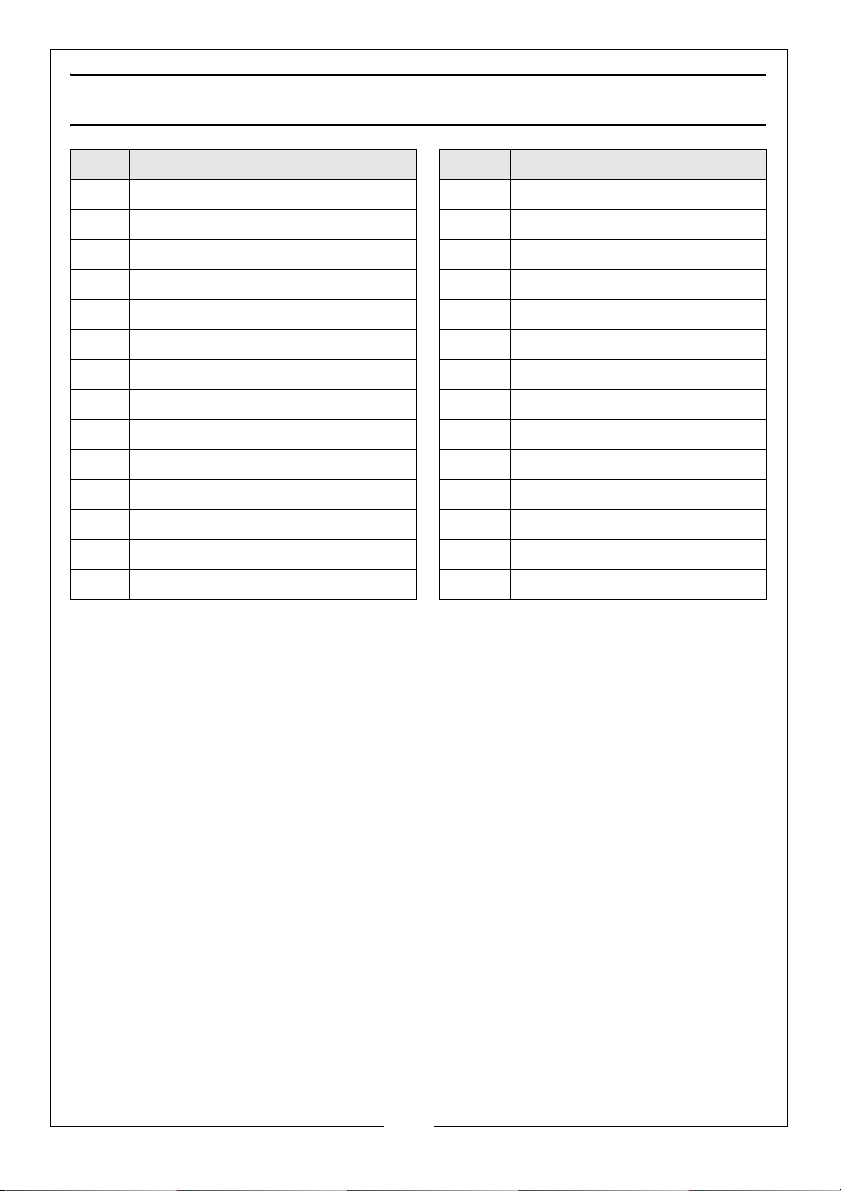
COMPONENT PARTS - FORKS & FRAME
No Description No Description
1 Handle assembly (see p 15) 15 Fork Frame
2 Retaining pin 16 Crank arm
3 Hinge pin 17 Connecting rod
4 Pump assembly (see p 14 18 Pivot shaft
5 Bearing ring 19 Circlip
6Base 20 Pivot pin
7 Retaining Circlip 21 Fork clevis
8 Bolt 22 Retaining pin
9 Main wheel assembly 23 Pivot Pin
10 Clevis pin 24 Castor
11 Retaining Pin 25 Castor pivot pin
12 Grub Screw 26 Retaining pin
13 Bolt 27 Ball bearing
14 Ball 28 Side plate
13
Parts & Service: 020 8988 7400 / E-mail: [email protected] or [email protected]
Page 14
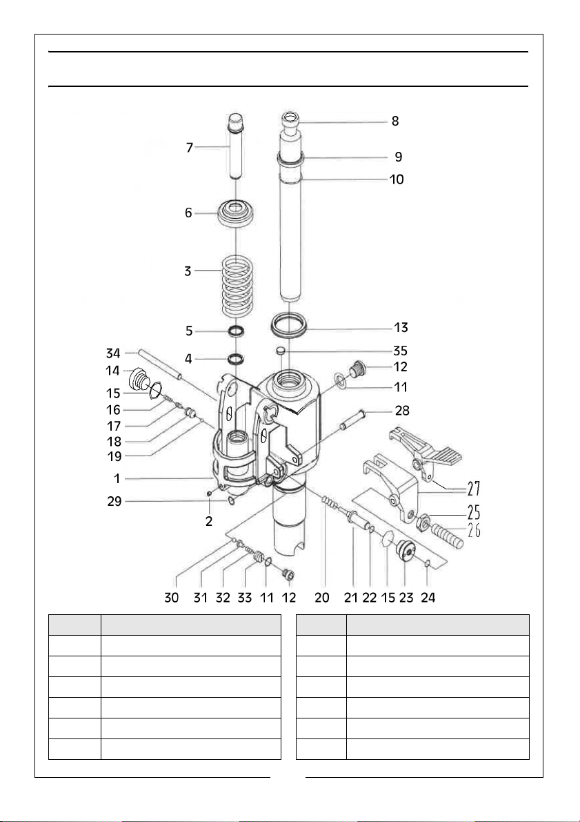
COMPONENT PARTS - PUMP
No Description No Description
1Base 12Bolt
2 End cap 13 Sealing ring
3 Compression spring 14 Bolt
4 Seal ring 15 Sealing washer
5 Dust ring 16 Compression spring
6Spring cap 17Valve core
14
Parts & Service: 020 8988 7400 / E-mail: [email protected] or [email protected]
Page 15
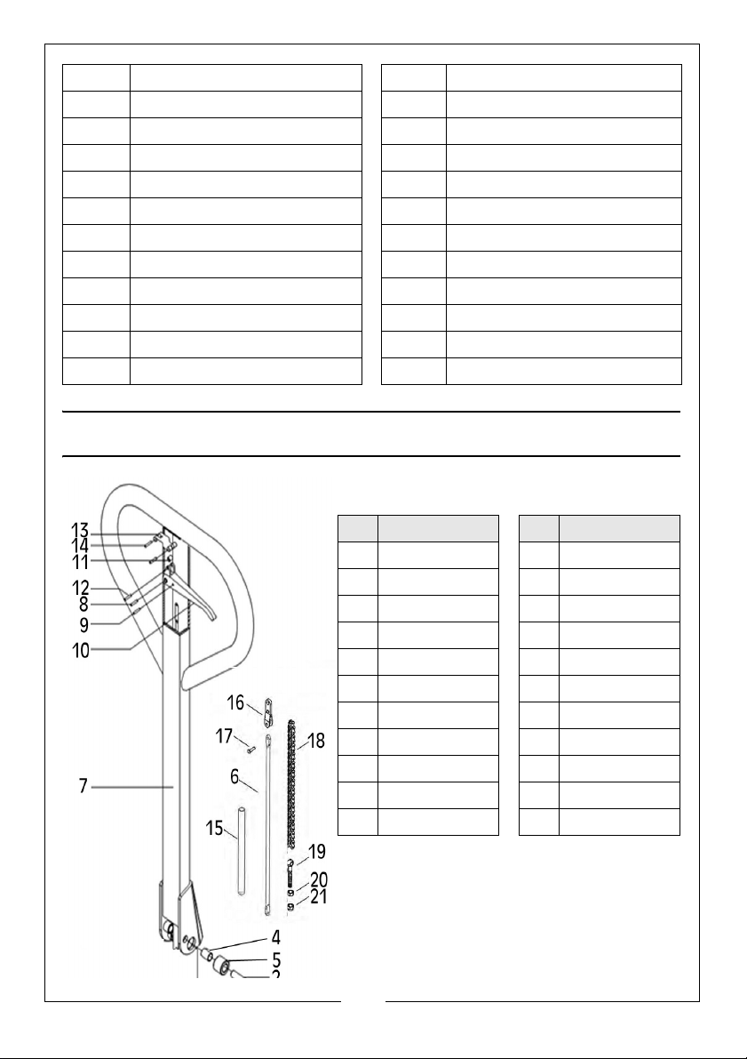
7 Pump core 18 Valve body
8 Piston rod 19 Steel ball
9 Dust ring 20 Compression spring
10 O-ring 21 Striker Pin
11 Sealing washer 22 O-ring
23 Striker pin seat 30 Steel ball
24 O-ring 31 Ball seat
25 Nut M6 32 Compression spring
26 Screw M6x25 33 Pressure adjusting screw
27 Lever plate 34 Pin
28 Stepped shaft 35 Magnet
29 Circlip 36 Foot pedal
COMPONENT PARTS - HANDLE ASSEMBLY
No Description No Description
1 Bearing 12 Pin 4 x 20
2 Hole pin 13 Fixed plate
3 Pin 4x20 14 Spring
4 Bearing 15 Sleeve
5 Wheel 16 Hinge plate
6 Pull rod 17 Rivet
7 Handle 18 Chain -19 links
8 Pin 6 x 31 19 Eyebolt
9 Pin 4 x 15 20 Nut M8
10 Knob 21 Nut M8
11 Wheel
15
Parts & Service: 020 8988 7400 / E-mail: [email protected] or [email protected]
Page 16
 Loading...