

Page 1
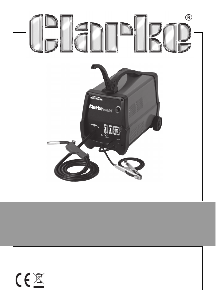
WARNING: Read these instructions before using the machine
Welder is supplied setup for no gas welding
NO GAS/GAS MIG WELDER
MODEL NO: MIG 145/152/180/196
PART NO: 6014505, 6015153, 6015182, 6015200
OPERATION & MAINTENANCE
INSTRUCTIONS
LS0416
Page 2
INTRODUCTION
Thank you for purchasing this CLARKE MIG Welder.
Before attempting to operate the machine, it is essential that you read this
manual thoroughly and carefully follow all instructions given. In doing so you
will ensure the safety of yourself and that of others around you, and you can
also look forward to the welder giving you long and satisfactory service.
GUARANTEE
This CLARKE product is guaranteed against faulty manufacture for a period of
12 months from the date of purchase. Please keep your receipt as proof of
purchase.
This guarantee is invalid if the product is found to have been abused or
tampered with in any way, or not used for the purpose for which it was
intended.
Faulty goods should be returned to their place of purchase, no product can
be returned to us without prior permission.
This guarantee does not effect your statutory rights.
ENVIRONMENTAL RECYCLING POLICY
Through purchase of this product, the customer is taking on the
obligation to deal with the WEEE in accordance with the WEEE
regulations in relation to the treatment, recycling & recovery and
environmentally sound disposal of the WEEE.
In effect, this means that this product must not be disposed of with general
household waste. It must be disposed of according to the laws governing
Waste Electrical and Electronic Equipment (WEEE) at a recognised disposal
facility.
2
Parts & Service: 020 8988 7400 / E-mail: [email protected] or [email protected]
Page 3
ACCESSORIES
The following are some of the accessories available from your CLARKE dealer.
Please quote the part numbers shown below:
PA RT D ES CR IP T IO N PA RT
NUMBER
Welding Wire
Spools
Welding Gas
Welding Tips 0.6 mm (pack of 5) 8132260
Gas regulator Gas regulator 8132000
Arc Activated
Headshields
Anti-splater spray 6000715
Swan Neck 8133740
Torch Shroud 8133735
Flux cored mild steel (mini
spool) 0.9mm
Mild steel (mini) - 0.6mm 8132100 Use for gas welding
Mild steel (mini) - 0.8mm 8132070 Use for gas welding
Stainless Steel 0.8mm (mini
spooll)
CO2 (250g)
CO2 (600g)
CO2/Argon Mix
0.8 mm (pack of 5) 8132270
1.0 mm (pack of 5) 8132275
A range of arc activated headshields are available, see your Clarke
dealer
8132110 Use for no gas welding
8132090
6000642 For welding mild steel
6000643 For welding mild steel
6000660 For welding stainless/
COMMENT
thin sheet mild steel
3
Parts & Service: 020 8988 7400 / E-mail: [email protected] or [email protected]
Page 4

CONTENTS
INTRODUCTION ............................................................... 2
GUARANTEE .................................................................... 2
ENVIRONMENTAL RECYCLING POLICY ......................... 2
ACCESSORIES ................................................................. 3
CONTENTS ....................................................................... 4
GENERAL SAFETY INSTRUCTIONS ................................... 5
ELECTRICAL CONNECTIONS (MIG 145) ........................ 8
ELECTRICAL CONNECTIONS (MIG 152,180,196) .......... 9
SAFETY SYMBOLS ............................................................ 10
UNPACKING ................................................................... 10
Opening The Side Panel ...................................................... 11
THE WELDING SHIELD ...................................................... 11
OVERVIEW ....................................................................... 12
The Control panel................................................................. 13
PREPARATION FOR USE .................................................. 14
Fitting The Wheels ................................................................. 14
Fitting The Handle ................................................................. 15
Mounting The Welding Wire Spool...................................... 15
Setting The Drive Roller Size ................................................. 16
Threading The Wire............................................................... 16
MIG WELDING PRINCIPLES ............................................. 18
GAS/NO-GAS SELECTION .............................................. 18
Welding Without Gas ........................................................... 19
Welding With Gas ................................................................. 19
OPERATING THE WELDER ................................................ 19
Preparing The Workpiece .................................................... 19
Operation .............................................................................. 20
Thermal Overload................................................................. 21
Duty Cycle............................................................................. 21
MAINTENANCE ............................................................... 22
RATING PLATE ................................................................. 23
SPECIFICATIONS ............................................................. 24
SPARE PARTS ................................................................... 24
TROUBLESHOOTING ........................................................ 25
DECLARATION OF CONFORMITY ................................... 27
4
Parts & Service: 020 8988 7400 / E-mail: [email protected] or [email protected]
Page 5
GENERAL SAFETY INSTRUCTIONS
WARNING: WHEN USING ELECTRICAL TOOLS, BASIC SAFETY
PRECAUTIONS SHOULD ALWAYS BE FOLLOWED TO REDUCE THE RISK OF
FIRE, ELECTRIC SHOCK AND PERSONAL INJURY
WARNING: READ ALL THESE INSTRUCTIONS BEFORE ATTEMPTING TO
OPERATE THIS PRODUCT AND KEEP THESE INSTRUCTIONS IN A SAFE PLACE.
ELECTRIC SHOCK
• Remove the plug from the socket
and wait 5 minutes to allow the
capacitors to discharge before
carrying out any servicing or
maintenance on this welder.
• Do not touch live electrical parts.
• Never use electrode holders or
cables which are damaged.
• Keep working environment,
equipment, cables and clothing
free from grease, oil, moisture and
dirt.
• Ensure welding machine has been
correctly earthed.
• The operator must be insulated
from the floor and work bench
using a dry insulation mat.
• Always ensure a second person is
present in case of accident.
• Never change electrodes with
bare hands or damp gloves.
• Keep welding cables away from
power cables.
• Regularly inspect the condition of
the cables for signs of damage.
• Remove plug from the mains
socket when not in use, do not
leave the machine unattended.
• Ensure earth clamp is secured to
bare metal adjacent to weld
seam, and when not in use is
Parts & Service: 020 8988 7400 / E-mail: [email protected] or [email protected]
insulated for safety. - Keep all
equipment well maintained.
• The operator shall prevent gas
cylinders in the vicinity of the work
piece from becoming part of the
welding circuit.
FUMES & GASES
• The welding process generates
hazardous fumes as a by-product.
Inhalation of these fumes is
hazardous to health.
• Keep your head away from the
weld to avoid breathing the fumes.
• If welding in confined spaces
ensure adequate ventilation and
use a fume extractor.
• By-products of welding can react
to create a toxic/explosive
environment.
FIRE OR EXPLOSION
Welding can cause fire and
explosions. Precautions should be
taken to prevent these hazards.
• Before starting work ensure the
area is clear of flammable
materials.
• Move any combustible materials to
a safe distance, especially
substances likely to generate a
dangerous vapour.
5
Page 6

• The welding arc can cause serious
burns. Avoid contact with skin.
• Sparks and molten metal are
ejected during welding. Take
precautions to prevent fire.
• Sparks and molten metal can pass
through gaps. Be aware that fire
can start out of sight.
• Do not weld pressurised containers.
or containers containing
flammable vapours e.g. fuel tanks.
• Always have appropriate fire
fighting equipment to hand
suitable for use in electrical
environments.
• Avoid carrying any fuels with you
e.g. cigarette lighters or matches.
PERSONAL PROTECTION
• The body should be protected by
suitable clothing.
• The use of neck protection may be
necessary against reflected
radiation.
• Arc machines generate a
magnetic field which is detrimental
to pacemakers. Consult your
doctor before going near active
welding equipment/operations.
• The UV and IR radiation generated
by welding is highly damaging to
the eye, causing burns. This can
also affect the skin.
• Always use suitable welding shields
equipped with appropriate
protection filters.
• Where there are pedestrians and
traffic ensure a protective screen is
used to avoid accidental arc glare.
• Do not weld in the vicinity of
children or animals and ensure no
one is looking before striking an
arc.
• Wear hearing protection if
required.
• Allow the weld time to cool. Hot
metal should never be handled
without gloves.
• Take care when adjusting or
maintaining the torch, that it has
had time to cool sufficiently and
the welder is disconnected from
the mains supply.
• First aid facilities and a qualified first
aid person should be available
unless medical facilities are close
by, for immediate treatment of
flash burns of the eyes and skin
burns.
• A hard hat should be worn when
others are working overhead.
• Flammable hair sprays/gels should
not be used by persons intending
to weld or cut.
PROTECTIVE CLOTHING
• Wear gauntlet gloves designed for
use in welding.
• Wear an apron, and protective
shoes.
• Wear cuffless trousers to avoid
entry of sparks and slag.
• Avoid oily greasy clothing.
• Protective head and shoulder
coverings should be worn when
overhead welding.
• Wear helmet with safety goggles or
glasses with side shields
underneath, appropriate filter
lenses or plates (protected by clear
glass). This is a MUST for welding
(and chipping) to protect the eyes
from radiant energy and spatter.
6
Parts & Service: 020 8988 7400 / E-mail: [email protected] or [email protected]
Page 7

Replace cover glass when broken,
pitted, or spattered.
NOTE: ALL protective wear inc. masks
& head shields MUST comply with PPE
Directive 89/686/EEC
GAS CYLINDERS:
• Gas cylinders should be located or
secured so that they cannot be
knocked over.
• Shield gas containers can explode
if damaged. Take care when
handling.
• Ensure gas cylinders are shut-off
when not in use and between
operations.
• Take care that a build-up of gas is
not permitted to form in confined
areas.
• Cylinders must be in an upright
position at all times during use and
storage.
• The gas cylinder must never come
in to contact with the electrode.
• Follow the manufacturer's
instructions for handling, storing
and using the gas bottle correctly
and safely.
• Use the correct equipment to
connect the gas bottle to the
welding torch.
ADDITIONAL SAFETY PRECAUTIONS
FOR MIG WELDING
• ALWAYS ensure that there is ample
free air circulating around the
outer casing of the machine, and
that the louvres are unobstructed.
• ALWAYS inspect the hose before
use to ensure it is in good condition.
• ALWAYS keep the free length of
torch hose outside the work area.
• ALWAYS remove all flammable
materials from the welding area.
• ALWAYS keep a fire extinguisher
handy;-Dry Powder, C02 or BCF,
NOT Water.
• NEVER remove any of the panels
unless the machine is
disconnected from the power
supply, AND never use the
machine with any of the panels
removed.
• NEVER attempt any electrical or
mechanical repair unless you are a
qualified technician. If you have a
problem with the machine contact
your local CLARKE dealer.
• Never use or store in a wet/damp
environment.
• NEVER continue to weld, if, at any
time, you feel even the smallest
electric shock. Stop welding
IMMEDIATELY, and DO NOT attempt
to use the machine until the fault is
diagnosed and corrected.
• NEVER point the MIG torch at any
person or animal.
• Never touch the MIG torch nozzle
until the welder is switched OFF and
the nozzle has been allowed to
cool off.
• NEVER allow the earth cable or
hose to become wrapped around
the operator or any person in the
vicinity.
7
Parts & Service: 020 8988 7400 / E-mail: [email protected] or [email protected]
Page 8
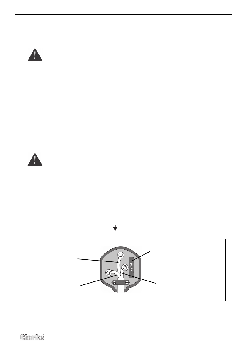
ELECTRICAL CONNECTIONS (MIG 145)
Plug must be BS1363/A approved.
Always fit a 13 Amp fuse.
Ensure that the outer sheath of the cable is firmly held by the clamp
Neutral
(Blue)
Live
(Brown)
Earth
(Green and Yellow)
WARNING! Read these electrical safety instructions thoroughly
before connecting the product to the mains supply.
Before switching the product on, make sure that the voltage of your electricity
supply is the same as that indicated on the rating plate. This product is designed to
operate on 230VAC 50Hz. Connecting it to any other power source may cause
damage.
This product may be fitted with a non-rewireable plug. If it is necessary to change
the fuse in the plug, the fuse cover must be refitted. If the fuse cover becomes lost
or damaged, the plug must not be used until a suitable replacement is obtained.
If the plug has to be changed because it is not suitable for your socket, or due to
damage, it should be cut off and a replacement fitted, following the wiring
instructions shown below. The old plug must be disposed of safely, as insertion into
a mains socket could cause an electrical hazard.
WARNING! The wires in the power cable of this product are
coloured in accordance with the following code:
Blue = Neutral Brown = Live Yellow and Green = Earth
If the colours of the wires in the power cable of this product do not correspond with
the markings on the terminals of your plug, proceed as follows.
• The wire which is coloured Blue must be connected to the terminal
which is marked N or coloured Black.
• The wire which is coloured Brown must be connected to the terminal
which is marked L or coloured Red.
• The wire which is coloured Yellow and Green must be connected to the
terminal which is marked E or or coloured Green.
We strongly recommend that this machine is connected to the mains supply via a
Residual Current Device (RCD)
If in any doubt, consult a qualified electrician. DO NOT attempt any repairs
yourself.
8
Page 9
ELECTRICAL CONNECTIONS (MIG 152,180,196)
WARNING! Read these electrical safety instructions thoroughly
before connecting the product to the mains supply.
Before switching the product on, make sure that the voltage of your electricity
supply is the same as that indicated on the rating plate. This product is
designed to operate on 230VAC 50Hz. Connecting it to any other power
source may cause damage.
Connect the mains lead, through a suitably fused isolator switch with a fuse in
accordance with the specifications.
A standard 13amp plug must not be used with these units.
WARNING! The wires in the power cable of this product are
coloured in accordance with the following code:
Blue = Neutral Brown = Live Yellow and Green = Earth
If the colours of the wires in the power cable of this product do not correspond
with the markings on the terminals of your plug, proceed as follows.
• The wire which is coloured Blue must be connected to the terminal
which is marked N or coloured Black.
• The wire which is coloured Brown must be connected to the ter minal
which is marked L or coloured Red.
• The wire which is coloured Yellow and Green must be connected to
the terminal which is marked E or or coloured Green.
We strongly recommend that this machine is connected to the mains supply via
a Residual Current Device (RCD)
If in any doubt, consult a qualified electrician. DO NOT attempt any repairs
yourself.
9
Parts & Service: 020 8988 7400 / E-mail: [email protected] or [email protected]
Page 10
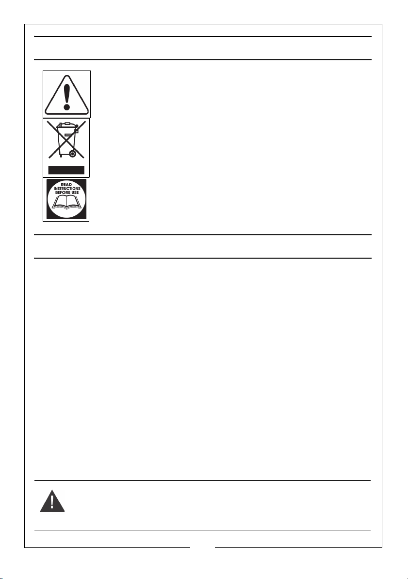
SAFETY SYMBOLS
General Warning, indicates that failing to follow these instructions
could result in injury or damage to the machine.
Recycle unwanted materials instead of disposing of them as
waste. All tools, accessories and packaging should be sorted,
taken to a recycling centre and disposed of in a manner which is
compatible with the environment.
Read Instruction manual before use.
UNPACKING
Any damage or deficiency should be reported to your CLARKE dealer
immediately. Some of the components are stored within the machine side
compartment.
The components include the following:
• 1 x Welder
• 1 x Carry Handle
• 1 x Pull Handle
• 1 x Handle Cap
• 1 x Handle Fixings Pack
• 3 x Copper Torch Tips - 2 x 0.8 mm, 1 x 1.0 mm (fitted)
• Mild Steel Wire Mini Spool 0.6mm
• Flux Cored mild steel wire mini spool 0.9 mm
• 1 x Instruction Manual
• 1 x Wheel Kit
WARNING: NEVER OPERATE THIS MACHINE WITH THE SIDE PANELS
PARTIALLY OPENED OR COMPLETELY REMOVED
10
Parts & Service: 020 8988 7400 / E-mail: [email protected] or [email protected]
Page 11
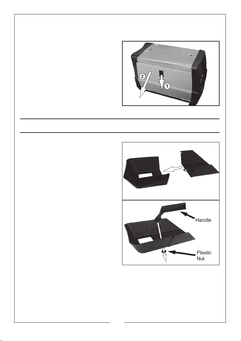
OPENING THE SIDE PANEL
IMPORTANT: Ensure that the welder is not connected to the mains supply.
1. Open the side panel, by pushing
the latch down and allowing the
side panel to drop down.
2. Remove any loose items that
have been transported inside
such as the handle, wheel kit etc
THE WELDING SHIELD
1. Push the two halves of the shield
together as shown, making sure
the hooks and pins on the side
engage correctly.
2. Place the handle into position
and secure using the plastic nut
provided.
3. Working from the inside of the
shield, insert the clear glass panel
into the recess in the shield,
followed by the dark glass panel.
• The clear glass must be inserted
first.
4. Insert the two plastic screws to
clamp the glass panels from the
inside of the mask.
When replacing the glass panels,
only use parts supplied by Clarke International. The dark panel is a certified,
specific optical class, and should not be exchanged for any other type.
5. The clear glass panel should be replaced when it becomes badly pitted.
11
Parts & Service: 020 8988 7400 / E-mail: [email protected] or [email protected]
Page 12
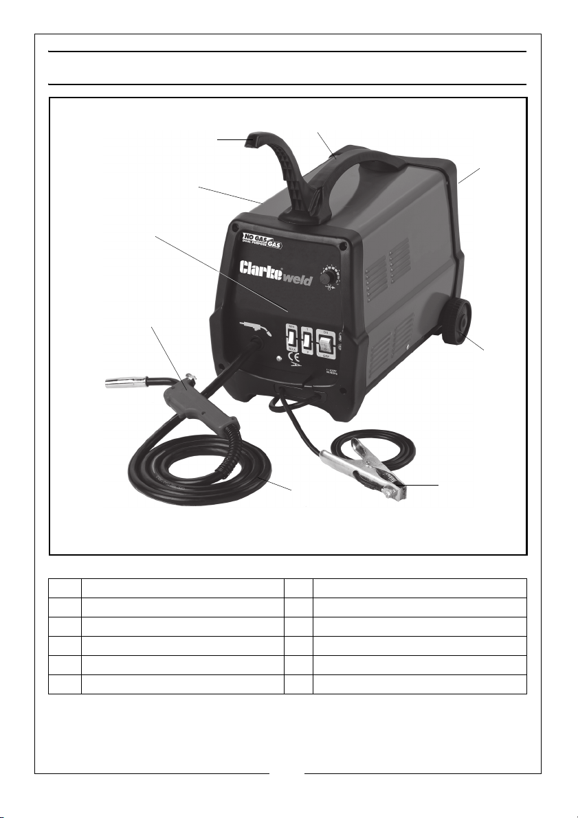
OVERVIEW
7
8
9
1
2
3
4
5
6
NO DESCRIPTION NO DESCRIPTION
1 Pull Handle 6 Torch
2 Carry Handle 7 Torch Hose
3 Gas Connection Point 8 Earth Clamp
4 Side Panel 9 Wheels
5Control Panel
12
Parts & Service: 020 8988 7400 / E-mail: [email protected] or [email protected]
Page 13
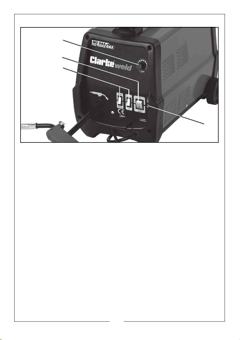
THE CONTROL PANEL
1
2
3
4
1. Thermal overload light. If the duty cycle is exceeded as a result of welding
too long with a high current, the yellow overload light will illuminate and the
welder will turn off. When the welder has cooled down (approx. 5 to 10
minutes), the power will be restored and welding can recommence.
2. Power ON/OFF switch. When the power is ON the green switch will be
illuminated. When the welder is no longer required, the Power On/Off switch
should be switched to the OFF position and the plug should be disconnected
from the mains supply.
3. Current setting switches MIN-MAX & 1-2. Used together these two switches
provide 4 increasing power levels as follows:
•MIN-1
•MIN-2
•MAX-1
• MAX-2.
4. Wire speed control knob. As a general rule, a higher current requires a
higher wire speed.
13
Parts & Service: 020 8988 7400 / E-mail: [email protected] or [email protected]
Page 14
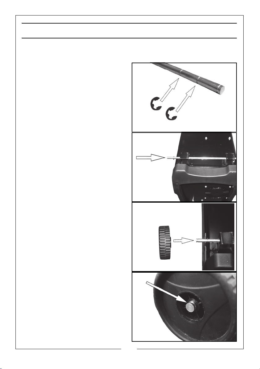
PREPARATION FOR USE
FITTING THE WHEELS
1. Fit two circlips onto the axle in the
positions shown.
2. Slip the axle into the wheel
supports.
3. Place two circlips onto the
opposite end of the axle in the
same positions.
4. Remove the cap on the wheel
and slide the wheel onto the axle.
5. Secure the wheel using a circlip.
6. Replace the wheel cap.
14
Parts & Service: 020 8988 7400 / E-mail: [email protected] or [email protected]
Page 15
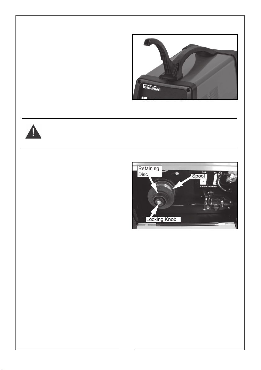
FITTING THE HANDLE
1. Fit the 2 handles together and
secure to the top of the welder
using the screws and washers
supplied.
MOUNTING THE WELDING WIRE SPOOL
Warning: Ensure that the welder is not connected to the mains supply.
NOTE: Spools of welding wire are available from your Clarke Dealer.
1. Open the side panel, by pushing
the latch down and allowing the
side panel to drop down.
2. Remove the locking knob and
retaining disc.
3. Place the spool of welding wire
(not supplied) over the spindle so
that it sits on the spring.
• Do not release the tension on
the wire as it will unravel causing feeding problems later.
• The wire will feed off the spool anticlockwise from the bottom of the
reel.
• The spool must be fitted with the correct orientation otherwise it will
not feed correctly.
15
Parts & Service: 020 8988 7400 / E-mail: [email protected] or [email protected]
Page 16
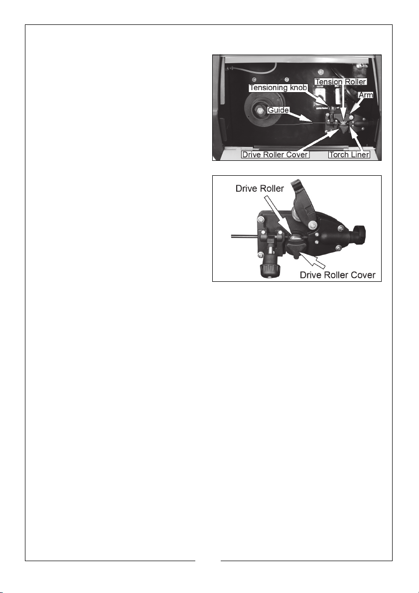
SETTING THE DRIVE ROLLER SIZE
1. Loosen the tensioning knob and
pivot it towards you
2. Lift up the arm.
3. Take hold of the triangular knob
on the drive roller cover and
rotate it 90°anticlockwise to
release it.
4. Pull the roller retainer off the drive
spindle to reveal the roller.
5. Pull the roller off the drive spindle.
• The groove size is stamped on
the corresponding side of the
roller. Select the groove size
according to the size of the
wire you are using and put the
roller back on the spindle with
your chosen side facing you.
6. Replace the drive roller cover
back onto the drive spindle with
the opening facing right.
7. Ensure that the flanges at the base of the drive roller cover, seat fully into
the circular recess in the main moulding and then rotate the drive roller
cover through 90° to lock it in place.
THREADING THE WIRE
IMPORTANT: Do not release the tension on the wire as it will unravel causing
feeding problems later.
1. Pull out the end of the wire from the spool, taking care not to release the
tension.
• We recommend you cut off and discard the first 10 cm of wire from
the spool to avoid burrs and then straighten the next 15 cm of wire
to help with feeding.
2. Loosen the tensioning knob and pivot it towards you.
3. Lift up the arm.
16
Parts & Service: 020 8988 7400 / E-mail: [email protected] or [email protected]
Page 17
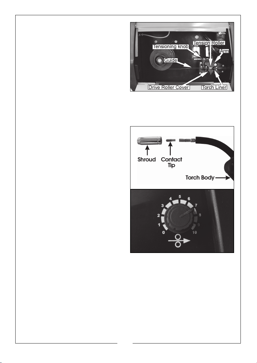
4. Pass the wire through the guide,
over the drive roller and into the
torch liner.
• Push about 10-15 cm into the
torch liner.
5. Lower the arm and replace the
tensioning knob.
• Tighten the tensioning knob
sufficiently to hold firmly, but do
not fully tighten.
NOTE: Correct tension will allow the wire to feed into the torch liner
smoothly, but will allow the drive roller to slip in the event of a
blockage.
6. Close the side panel of the
welder.
7. Pull off the torch shroud with a
twisting movement, then unscrew
the contact tip.
8. Connect the welder to the power
supply and switch ON.
9. Set the ‘WIRE FEED’ rotary control
on the front panel to position 7 or
8 and squeeze the trigger on the
torch body.
• The wire will feed through the
hose until it appears at the
torch tip.
• Ensuring the hose is free from
kinks during this process will
assist the wire in its passage
through the hose liner.
10. Release the trigger and switch off the welder and disconnect the machine
from the mains supply.
11. Refit the appropriate size contact tip (0.9 mm, for no gas welding is
supplied fitted) to suit your wire. then replace the shroud.
• A spare 0.8 mm tip is supplied loose and should be used when using
0.6/0.8 mm mild steel solid wire.
12. Trim the welding wire so that it protrudes no more than 5 mm from the end
of the contact tip.
17
Parts & Service: 020 8988 7400 / E-mail: [email protected] or [email protected]
Page 18
MIG WELDING PRINCIPLES
MIG (Metal Inert Gas) welding allows you to fuse together two similar metals
without altering the properties of the metal.
A consumable wire electrode is continuously fed through the welding torch
that is fitted with a concentric gas nozzle. the wire is connected to a high
voltage supply which creates an electric arc between the electrode (the
wire) and the workpiece. The arc is used to create the required heat to turn
the metal into a molten state. The wire is used as both the electrode and as a
filler.
The gas is used to prevent oxidation and to shield the arc and the weld from
atmospheric contamination. The choice of gas is dependent upon the
material being welded, Two types are available from Clarke International.
Carbon Dioxide (CO
CO2/Argon Mix
When using the welder in a gasless configuration the shielding gas is created
from the flux within the welding wire.
When using the welder outside, you may need to erect a wind break to make
sure the shielding gas is not blown away, thereby leaving a poor quality weld.
) For Mild Steel Part No. 6000642
2
For thin sheet metal-Mild
Steel / Stainless Steel
Part No. 6000660
GAS/NO-GAS SELECTION
The welder can be configured to
weld, with or without a gas supply
according to the type of welding
wire being used.
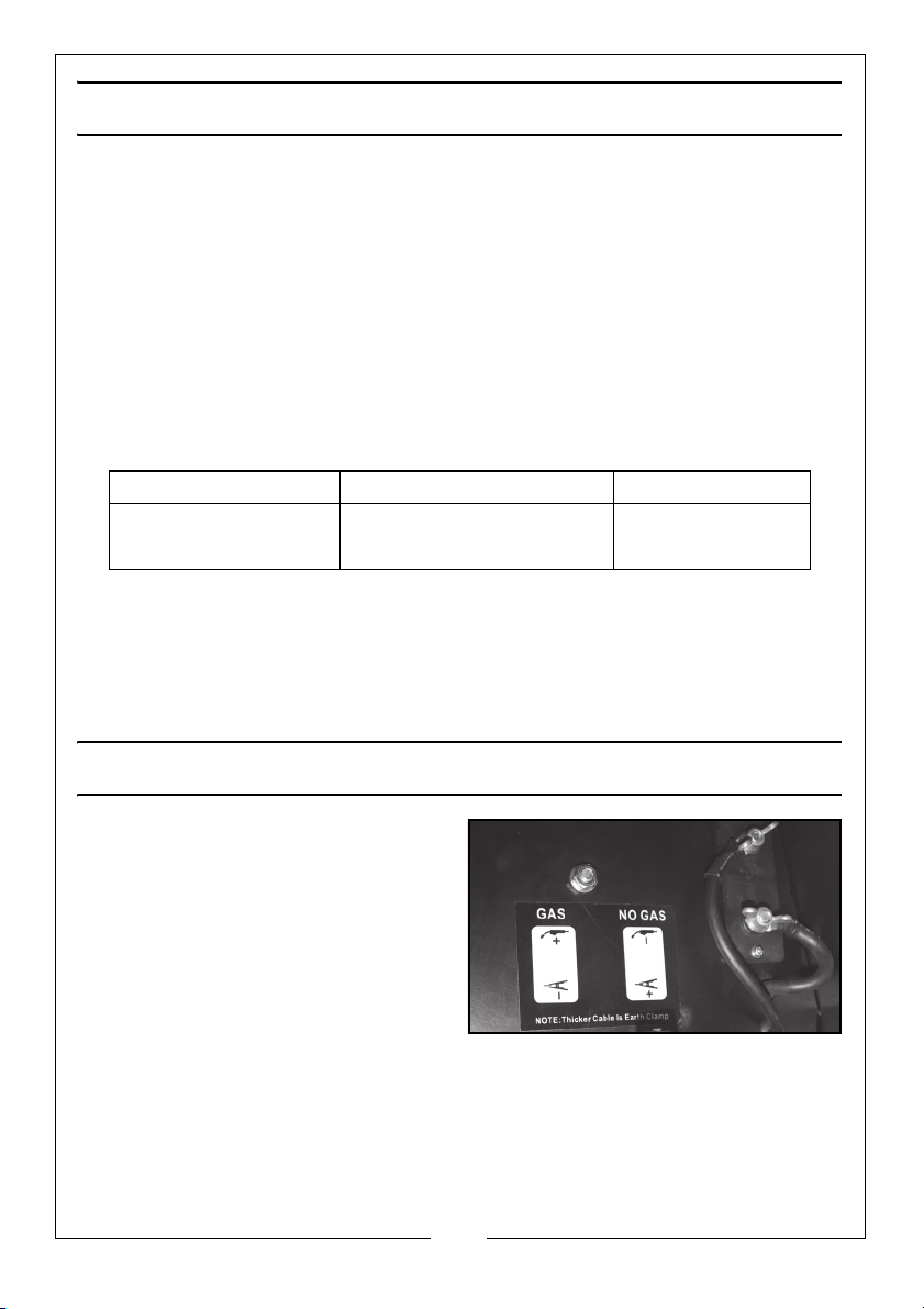
• Mild Steel solid core (With Gas),
• Flux Cored (No Gas)
18
Parts & Service: 020 8988 7400 / E-mail: [email protected] or [email protected]
Page 19
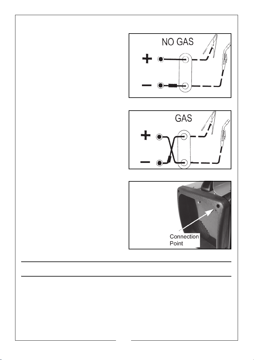
WELDING WITHOUT GAS
1. If using 0.9mm flux cored wire,
connect the terminal as shown.
• The earth cable (Thicker Lead)
should be connected to the
positive (Red) terminal.
• The cable from torch (Thinner
Lead) should be connected to
the Negative (Black) terminal
WELDING WITH GAS
1. If using solid cored wire 0.6/0.8mm
mild steel, connect the terminal as
shown.
• The earth cable (Thicker Lead)
should be connected to the
negative (Black) terminal.
• The cable from torch (Thinner
Lead) should be connected to
the positive (Red) terminal.
CONNECTING THE GAS SUPPLY
2. Connect a bottled gas supply to
the small tube at the back of the
welder.
OPERATING THE WELDER
PREPARING THE WORKPIECE
The area being welded should be perfectly clean. Any coating, plating or
corrosion must be removed, otherwise a good weld will be impossible to
achieve.
Attach the earth clamp to the workpiece as close to the point of weld as
possible, without it being intrusive.
19
Parts & Service: 020 8988 7400 / E-mail: [email protected] or [email protected]
Page 20
OPERATION
CAUTION: THE DUTY CYCLE MUST BE ADHERED TO TO PREVENT THE
THERMAL OVERLOAD PROTECTION FROM ACTIVATING
1. With the welding current set and the wire trimmed, set the wire feed
control to 6.
2. Plug the machine into the mains supply and switch ON the machine.
3. Cover your face with a welding mask or welding helmet.
• This is essential.
4. Lower the torch to the workpiece with one hand and approach the work
with the torch tip at an angle of about 35
• As the wire touches the workpiece, an arc will be struck.
5. In order to produce a satisfactory weld, the controls may be fine tuned as
required. This will come with practice.
NOTE: MIG welding is an acquired skill, it is strongly advised that, if you
are not fully familiar with this type of welding, you practice on a
piece of material with the same characteristics as your
workpiece, until you are satisfied with the result, and you have
fine tuned your welder to produce a satisfactory weld.
NOTE: One of the problems experienced with novice welders, is the
welding wire sticking to the contact tip. This is as a result of the
wire feed speed being too slow. It is always better therefore to
start with too high a speed, and back off slightly, to avoid the
possibility of the wire welding itself to the tip. This is the reason
position 6 is recommended for start up.
NOTE: The Wire Feed control is for fine tuning the wire speed. The speed
of wire delivery will increase automatically as the current is
increased. Therefore, once the ideal speed is achieved by fine
tuning, it should not be necessary to adjust this control when the
welding current is changed.
NOTE: Listen to the sound made. An irregular crackling sound denotes
too high a wire speed. Decrease the speed until a regular, strong
buzzing sound is heard.
o
and pull the torch trigger fully.
20
Parts & Service: 020 8988 7400 / E-mail: [email protected] or [email protected]
Page 21
THERMAL OVERLOAD
The ‘Thermal Overload’ shuts off the
welder when it becomes too hot,
due to the duty cycle being
exceeded. This is to prevent any
damage to the machine.
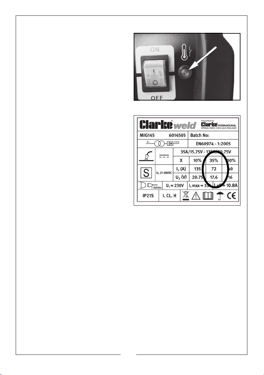
When this occurs, the warning lamp
shown will glow (amber). Allow the
welder to cool, until the amber light
extinguishes before resuming work.
DUTY CYCLE
These welders are covered by
regulations EN 60974-1 and EN 50199,
where the duty cycle is expressed as
a percentage of time the machine
may be used in a given period for a
specified welding current.
Using the example shown, which is an
illustration of the data plate;-
e.g. when welding at 72 amps the
machine may be used for 3.5 minutes
(35%) in any 10 minute period.
21
Parts & Service: 020 8988 7400 / E-mail: [email protected] or [email protected]
Page 22
MAINTENANCE
WARNING: ELECTRICITY CAN KILL - NEVER TOUCH LIVE ELECTRICAL
COMPONENTS.
WARNING: DISCONNECT THE POWER SUPPLY BEFORE ALL INSPECTIONS
AND MAINTENANCE OPERATIONS. BEWARE HOT SURFACES.
WARNING: ALWAYS LET THE WELDER COOL DOWN BEFORE ACCESSING
INTERNAL COMPONENTS.
Frequency of maintenance operations depends on the operating conditions,
how intensively the welder is used and how clean or dirty the welding site is
(aggressive environments etc).
Always inspect the earth cable and torch hose before use, to ensure they are
in perfect condition and that the earth clamp is clean and secured correctly
to the cable.
Check the hose for security and damage.
As a general rule the power supply should be inspected at least annually.
Consult your CLARKE dealer for advice if necessary.
Wire feed unit:
The feed roller wire guide plays an important part in obtaining consistent
results. Clean the rollers weekly, especially the feed roller groove, removing all
dust deposits.
Torch:
Protect the torch hose assembly from mechanical wear. Clean the liner from
the machine forwards by using compressed air. If the liner is blocked it must be
replaced.
Contact tip:
The contact tip is a consumable item and must be replaced when the bore
becomes enlarged or oval. The contact tip MUST be kept free from spatter to
ensure an unimpeded flow of gas.
To keep the contact tip free from spatter, we recommend the use of antispatter spray (MIG/6000715) available from your CLARKE dealer.
Torch shroud:
The torch shroud must also be kept clean and free from spatter. Build-up of
spatter inside the gas cup can cause a short circuit at the contact tip which
will result in expensive machine repairs.
22
Parts & Service: 020 8988 7400 / E-mail: [email protected] or [email protected]
Page 23
RATING PLATE
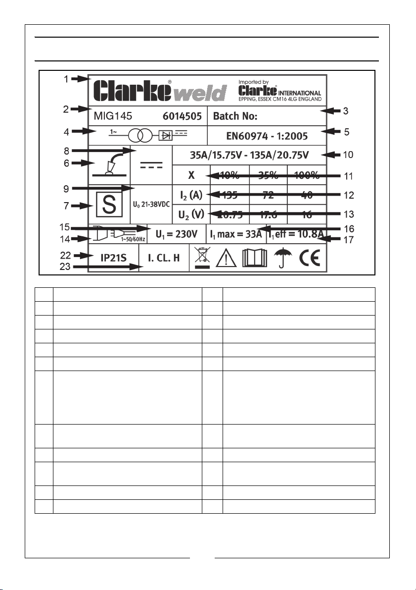
1 Name and address of manufacturer 13 Load Voltage symbol
2 Model number, part number 14 Energy Input symbol
3 Batch number 15 Rated supply voltage
4 Single phase transformer-rectifier 16 Rated maximum supply current
5 British Standards applied 17 Maximum effective supply current
6 Welding process 18 N/A
7 This symbol indicates that the unit is
suitable for carrying out welding
operations in an environment which
has an increased risk of electric
shock.
8 Welding Current symbol - direct cur-
rent.
9 Rated no-load voltage 21 N/A
10 Min+max welding current and corre-
sponding load voltages
11 Duty Cycle symbol 23 Class of protection.
12 Rated Welding Current symbol 24 N/A
19 N/A
20 N/A
22 Degree of protection
23
Parts & Service: 020 8988 7400 / E-mail: [email protected] or [email protected]
Page 24
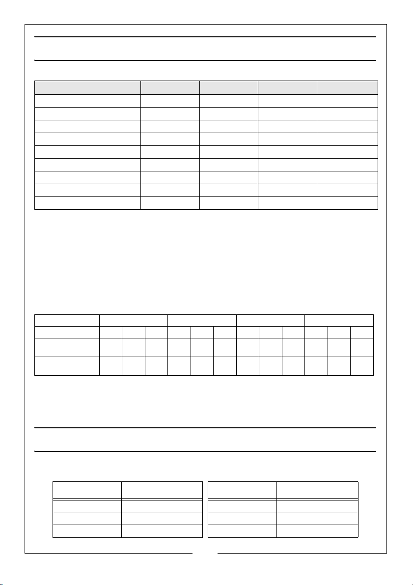
SPECIFICATIONS
Model MIG 145 MIG152 MIG180 MIG196
Part No 6014505 6015153 6015182 6015200
Weight 27.5 kg 28.4 kg 30.5 kg 30.6 kg
Dimensions (l x w x h) mm 500 X 278 X 366 482 x 278 x 395 500 x 278 x 388 500 x 275 x 390
Power Supply 230 V @ 50Hz 230 V @ 50Hz 230 V @ 50Hz 230 V @ 50Hz
IP Rating IP21S IP21S IP21S IP21S
Output Min/Max Amps 35 /135 Amps 40 / 140 Amps 40 / 160 Amps 40 / 180 Amps
Open Circuit Voltage 21-38 V DC 21-38 V DC 21-38 V DC 21-38 V DC
Rated Max Input Current (A)33343537
Cutting Capacity (Mild Steel) 4 mm 4-5 mm 5 mm 5-6 mm
The details and specifications contained herein, are correct at the time of going to print.
However, CLARKE International reserve the right to change specifications at any time
without prior notice.
DUTY CYCLE
The duty cycle determines the machine ‘down time’. i.e 10% means 1 minutes operation
followed by 9 minutes of rest. The duty cycle must be adhered to to prevent the thermal
cutout protection from activating.
MIG145 MIG152 MIG180 MIG196
Duty Cycle (%)
Rated Welding
Current (A)
Conventional
Load Voltage (V)
10 35 100 10 35 100 10 35 60 10 60 100
135 72 40 140 75 40 160 85 60 180 74 60
20.7517.616211816221817231817
Do not exceed the stated duty cycle for this machine. Failure to heed
this warning may invalidate your warranty.
SPARE PARTS
A range of spare parts are available from your Clarke dealer, incuding the following.
DESCRIPTION PART NUMBER DESCRIPTION PART NUMBER
0.6mm tips 8132260 Shroud 8133735
0.8mm tips 8132270 Swan neck 8133740
1.0 mm tips 8132275
24
Parts & Service: 020 8988 7400 / E-mail: [email protected] or [email protected]
Page 25
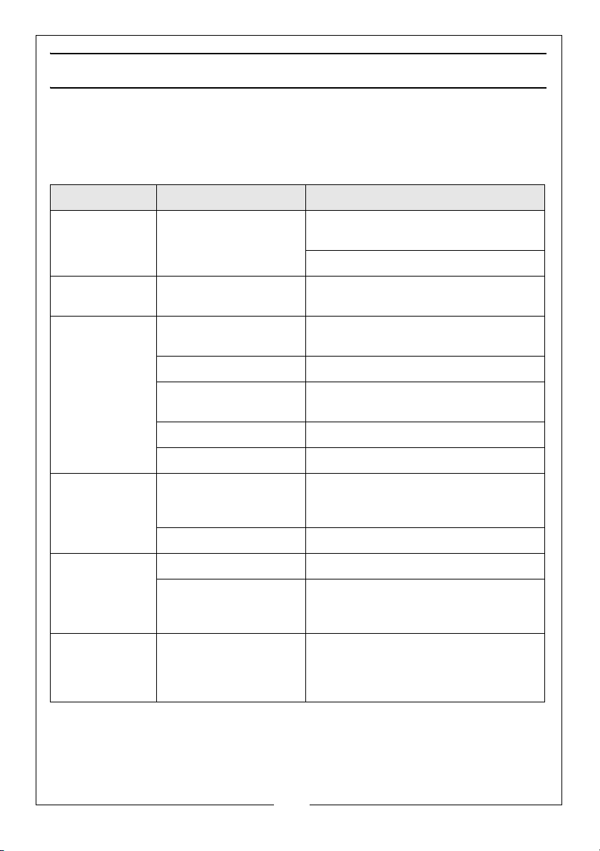
TROUBLESHOOTING
Your CLARKE MIG Welder has been designed to give long and trouble free
service. If, however, having followed the instructions in this booklet carefully,
you still encounter problems, the following points should help identify and
resolve them.
PROBLEM CAUSE SOLUTION
No response from
welder
Welder does not
feed wire
Feed motor running but no wire
being fed from
welder tip
Wire welds itself
to tip
Wire feeds into
‘birds nest’ tangle
Check fuses and mains
lead
Feed motor has malfunctioned.
Insufficient Feed Roller
pressure
Burr on end of wire Re-cut wire square with no burr
Liner blocked or damaged
Inferior wire Use only good “clean” wire
Roller worn out Replace roller
Wire feed speed too low Unscrew tip, cut wire and fit new tip
Wrong size tip Fit correct size tip
Wire welded to tip As above plus reduce feed roller pressure
Wire liner damaged preventing smooth operation
Replace fuses as necessary, If problem
persists return welder to your local dealer
Check fuse size
Return welder to your local dealer
Increase roller pressure
Clean with compressed air or replace
liner.
Increase wire speed before operating
again
Renew wire liner
Loose coils of
wire tangle
around wire drum
inside machine
Locking knob too slack Tighten Locking Knob slightly. Do not
over-tighten
25
Parts & Service: 020 8988 7400 / E-mail: [email protected] or [email protected]
Page 26
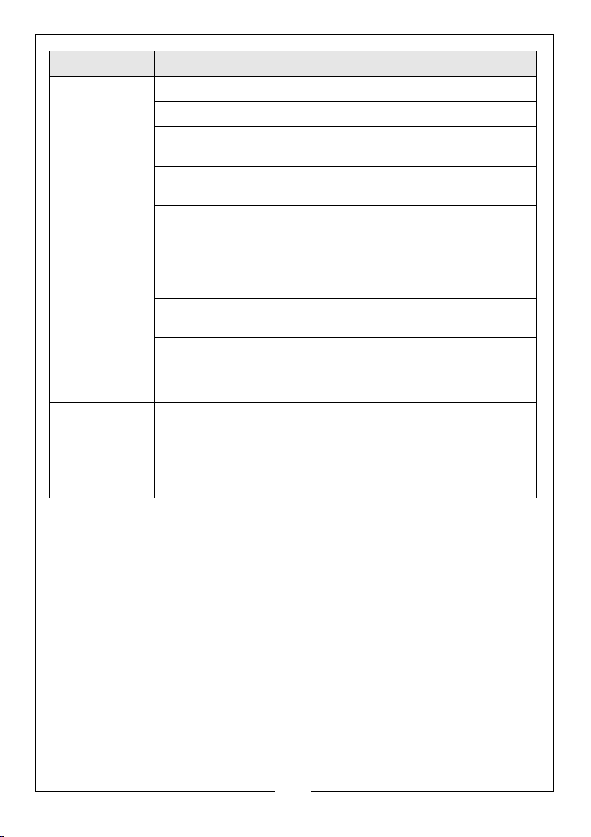
PROBLEM CAUSE SOLUTION
Erratic wire feed Locking Knob too tight Loosen Locking Knob slightly
Feed roller worn Check and replace if necessary
Insufficient pressure on
feed roller
Wire dirty, rusty, damp or
bent
Liner partially blocked Clean with compressed air
Poor quality
welds
Welder cuts out
whilst in use
If you have any problems which cannot be resolved by reference to the above, or if you
require spare parts for your welder please contact your local Clarke dealer.
Insufficient gas at weld
area
Rusty, painted, damp, oil
or greasy workpiece
Rusty/dirty wire Ensure wire is clean and dry
Poor earth contact Check earth clamp/workpiece connec-
Duty cycle exceeded
(auto cut-out operates)
Increase pressure on feed roller
Caution: Do not over-tighten
Re-cut wire and ensure it is clean
Check that gas is not being blown away
by draughts and if so move to a more
sheltered work area. If not increase gas
supply
Ensure workpiece is clean and dry
tion
Allow welder to cool 15-30 mins before
continuing
Note: If duty cycle is continually
exceeded, damage to the welder may
result, and welder output is probably too
small for application
26
Parts & Service: 020 8988 7400 / E-mail: [email protected] or [email protected]
Page 27
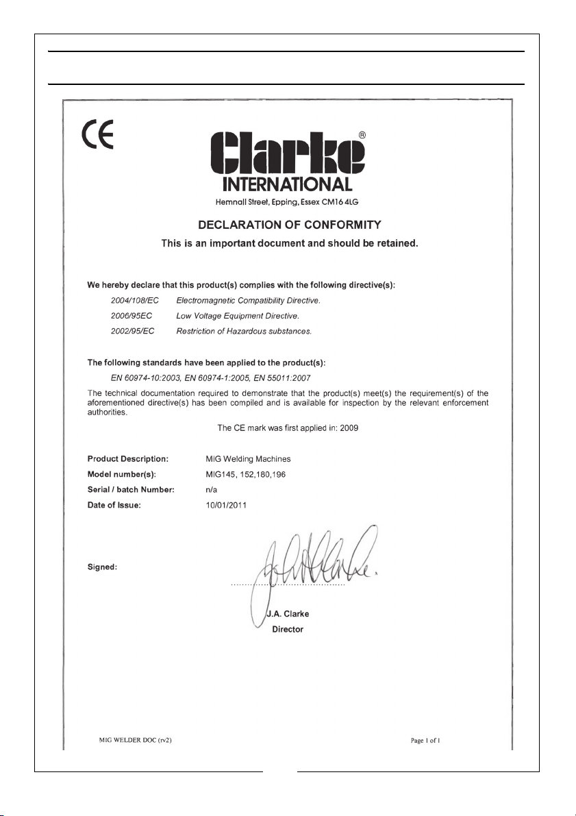
DECLARATION OF CONFORMITY
27
Parts & Service: 020 8988 7400 / E-mail: [email protected] or [email protected]
Page 28
 Loading...