

Page 1
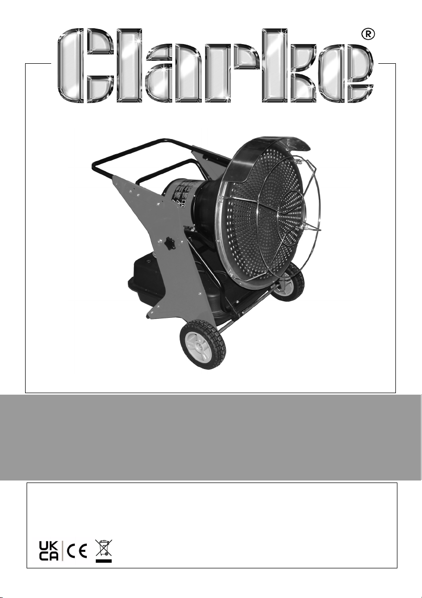
INFRARED DIESEL HEATER
MODEL NO: DEVIL IRD40B
PART NO: 6920417
OPERATION & MAINTENANCE
INSTRUCTIONS
ORIGINAL INSTRU CTIONS GC0621 - iSS.4
Page 2
INTRODUCTION
Thank you for choosing this Clarke Infrared Heater. Before attempting to use
this product, please read this manual thoroughly and follow the instructions
carefully. In doing so you will ensure the safety of yourself and that of others
around you, and you can look forward to your heater giving you long and
satisfactory service.
Please keep these instructions in a safe place for future reference.
FUNCTION AND OPERATING PARAMETERS
This is a multi-fuel (Diesel or Paraffin), forced air heater. It’s intended use is for
drying and the warming of commercial/industrial buildings where adequate
ventilation is provided.
• It must be operated as prescribed in the operating manual.
• It is not intended to be used for domestic use or for the heating of
habitable areas.
• It is not intended to be used to reach and maintain a certain level of
human thermal comfort within an enclosed space in which the heater is
situated.
• It is not intended to be used in enclosed areas with restricted ventilation.
• It is not for use in areas with high levels of fluctuating drafts.
• It is not intended for warming animals or live stock.
GUARANTEE
This product is guaranteed against faulty manufacture for a period of 12
months from the date of purchase. Please keep your receipt which will be
required as proof of purchase.
This guarantee is invalid if the product is found to have been abused or
tampered with in any way, or not used for the purpose for which it was
intended.
Faulty goods should be returned to their place of purchase, no product can
be returned to us without prior permission.
This guarantee does not effect your statutory rights.
2
Parts & Service: 020 8988 7400 / E-mail: [email protected] or [email protected]
Page 3
ENVIRONMENTAL RECYCLING POLICY
Through purchase of this product, the customer is taking on the
obligation to deal with the WEEE in accordance with the WEEE
regulations in relation to the treatment, recycling & recovery and
environmentally sound disposal of the WEEE.
In effect, this means that this product must not be disposed of with general
household waste. It must be disposed of according to the laws governing
Waste Electrical and Electronic Equipment (WEEE) at a recognised disposal
facility.
If disposing of this product or any damaged components, do not dispose of
with general waste. This product contains valuable raw materials. Metal
products should be taken to your local civic amenity site for recycling of metal
products.
TECHNICAL SPECIFICATION
Dimensions (L x W x H) 635 x 925 x 860 mm
Weight (empty) 28.4 kg
Fuel Diesel/Paraffin
Fuel consumption 3.8l/h - 3.2 kg/h
Fuel Tank capacity 38 litres
Ignition type Direct spark ignition
Continuous working time 10 hr (before re-fueling)
Over heating protection
Max output 40 kW (136,484 Btu/h)
Operating Temperature
Duty cycle S1 (continuous)
Fuel pump pressure Factory set at 6.5 bar
Electrical supply 230V 50 Hz
Ingress Protection degree IPX4
Sound Power level 67 dB LpA
o
120
C
-20 - 45oC
3
Parts & Service: 020 8988 7400 / E-mail: [email protected] or [email protected]
Page 4
GENERAL SAFETY PRECAUTIONS
CAUTION: FAILURE TO FOLLOW THESE PRECAUTIONS COULD RESULT IN
PERSONAL INJURY, AND/OR DAMAGE TO PROPERTY.
CAUTION: DUE TO THE HIGH SURFACE AND EXHAUST TEMPERATURES,
ADULTS AND CHILDREN MUST KEEP CLEAR OF THE HEATER TO AVOID
BURNS OR CLOTHING IGNITION.
GENERAL
1. Always read and ensure you fully understand the following precautions and
the hazards associated with this heater. Do not allow anyone who has not
read these instructions to operate it.
2. Always check for damage before use. Any damage should be properly
repaired. If in doubt, do not use the heater and consult your local dealer.
3. Never carry out any modifications to this heater. If experiencing difficulty of
any kind consult your local Clarke dealer.
4. Use the heater in accordance with any applicable fire regulations.
OPERATING ENVIRONMENT
1. This heater is intended for drying & warming of commercial/industrial
buildings where adequate ventilation is provided. It is not for domestic use
or heating habitable areas.
2. Do not expose the heater or power cable to rain or wet conditions. Any
water entering the heater will increase the risk of electric shock.
3. Never use the heater where petrol, paint thinners or other highly flammable
vapour or where high levels of airborne dust may be present.
4. The heater should always be positioned well away from sources of airbourne dust, as ingress of dust into the heater may cause it to malfunction.
It will be beneficial to shield the heater from a dusty work environment.
5. Never locate the heater facing combustible materials.
6. Always locate the heater on a level, flat, fireproof floor. Ensure that the
heater is correctly and safely positioned as described on page11.
7. Disconnect the heater from the power supply when not in use.
8. Never place anything on top of the heater.
9. Always keep combustibles, at least 3 m from the front of the heater.
10. Operate only on a stable, level surface.
11. Use only in accordance with local building regulations.
4
Parts & Service: 020 8988 7400 / E-mail: [email protected] or [email protected]
Page 5

12. Do not locate the heater close to an adjacent wall or ceiling. Always allow
at least 3 metres clearance. Avoid placing the heater directly below
power socket outlets
VENTILATION
Even though this heater operates very close to 100 percent combustion
efficiency, it still produces small amounts of carbon monoxide.
Carbon monoxide (CO) is toxic. It can build up in a confined spaces and
failure to provide adequate ventilation can be fatal.
The early symptoms of asphyxiation caused by inadequate ventilation are:
• headache • nausea
• dizziness • dry mouth or sore throat
1. Only use in well ventilated areas and make sure that ample ventilation is
present if the heater is being started following a long period without use.
2. Never attach any duct work to the front of the heater.
3. Never cover or impede airflow into or out of the heater.
WE RECOMMEND THE USE OF A CARBON MONOXIDE DETECTOR
PERSONAL SAFETY
1. When the heater is used in the presence of other people the user is
responsible for informing those present of the safety precautions and of the
hazards involved.
2. The heater is not to be used by children or people with reduced physical,
sensory or mental capabilities, or lack of knowledge.
3. Always ensure that people and animals are at least 3 m away from the
front of the heater when in operation.
4. Never leave a heater unsupervised while in use - someone should always
be made responsible for monitoring it.
5. Do not move or service the heater while hot or in use.
6. This heater will be hot when in use and should not be touched until it has
fully cooled down after shutting down.
REFUELLING
1. Always refuel in a well ventilated area.
2. Always allow the heater to cool down before re-fuelling.
3. Always refuel away from any source of heat.
5
Parts & Service: 020 8988 7400 / E-mail: [email protected] or [email protected]
Page 6

4. Never overfill the tank, only fill to the level specified.
5. Use only clean diesel oil or paraffin. NEVER use gasoline, paint thinners,
alcohol or other highly flammable fuels.
6. Take care not to spill fuel onto the power cable as this could damage the
insulation.
7. Never move, replenish the fuel supply or handle the heater when it is hot, or
in use. Turn it off and wait for it to cool down first.
ELECTRICAL SAFETY
1. Electrical appliances must match the power outlet. Never modify the plug
in any way. Do not use adaptor plugs with earthed (grounded) appliances.
Correct plugs and outlets will reduce the risk of electric shock.
2. Do not abuse the electrical cable. Never use the cable for pulling or
unplugging the heater. Keep the cable away from sources of heat, oil,
sharp edges or moving parts. Damaged or tangled cables increase the risk
of electric shock.
3. Keep the mains cable well away from machines and ensure an adequate
electrical supply is close at hand so that the operation is not restricted by
the length of the cable.
4. Always disconnect from the mains supply before moving the heater or
performing any maintenance tasks.
5. Inspect the mains cable regularly for signs of damage. DO NOT use if it is
damaged and always keep it away from the source of heat.
6. If the power cable is damaged, it must be replaced by the manufacturer,
its service agent, or similarly qualified persons in order to avoid a hazard.
SERVICE & REPAIRS
1. Check the heater for damage before use. DO NOT use if the heater is
damaged. Any damage should be properly repaired or the part replaced.
If in doubt, DO NOT use the heater. Consult your local dealer.
2. When necessary, have your heater serviced or repaired by a qualified
person using identical replacement parts. This will ensure that the safety of
the heater is maintained.
6
Parts & Service: 020 8988 7400 / E-mail: [email protected] or [email protected]
Page 7
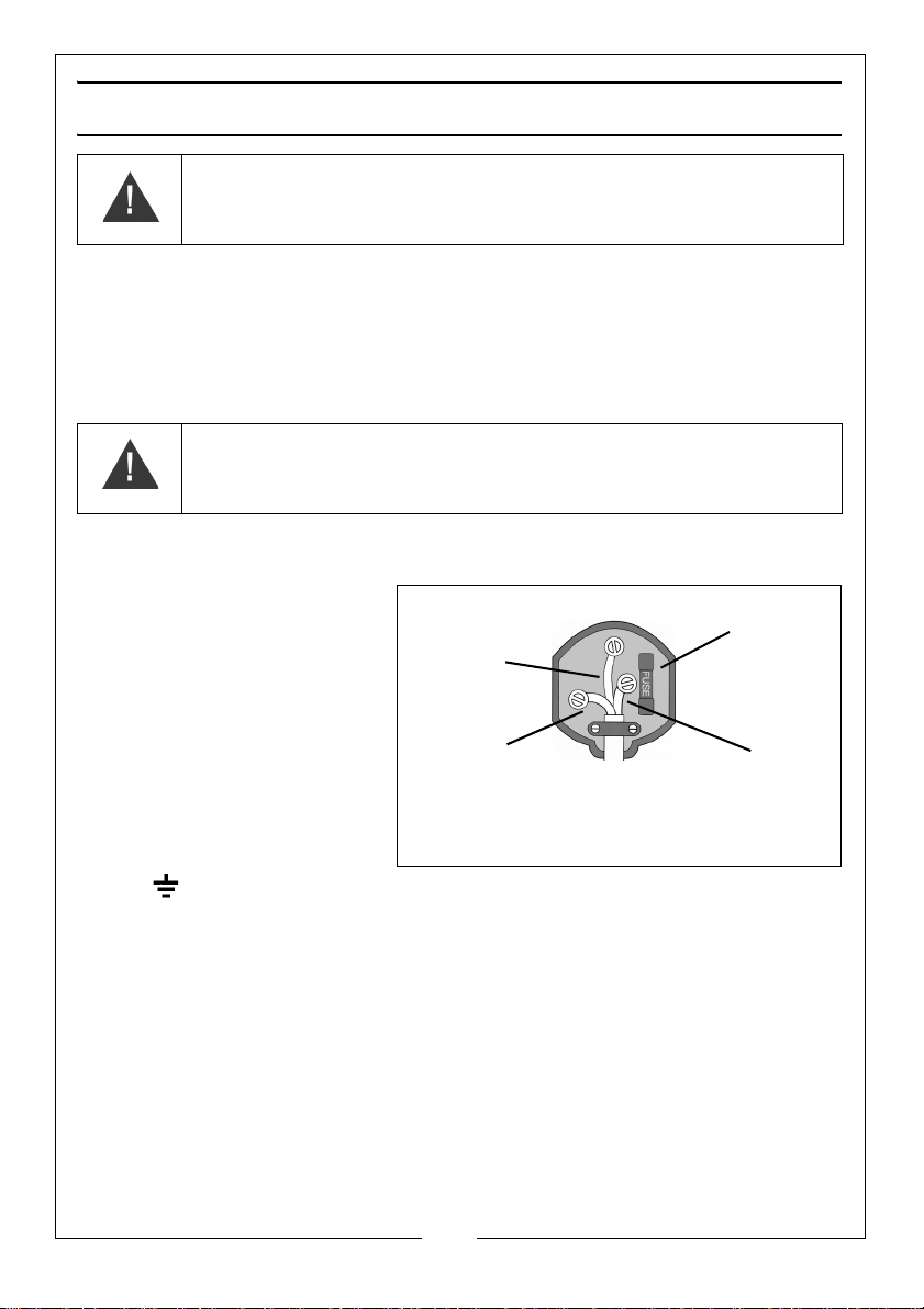
ELECTRICAL CONNECTIONS
Plug must beB1363/A approved.
Always fit
Ensure the outer sheath of the
Neutral
(Blue)
Live
(Brown)
Earth
(Green and
a 13 Amp
fuse.
cable is firmly held by the clamp
Yellow)
WARNING: READ THESE ELECTRICAL SAFETY INSTRUCTIONS
THOROUGHLY BEFORE CONNECTING THE PRODUCT TO THE MAINS
SUPPLY.
Connect the mains lead to a standard 230Volt 50Hz electrical supply through
an approved 13 amp BS1363 plug or a suitably fused isolator switch.
If the plug has to be changed because it is not suitable for your socket, or due
to damage, it should be cut off and a replacement fitted, following the wiring
instructions shown below. The old plug must be disposed of safely, as insertion
into a mains socket could cause an electrical hazard.
WARNING: THE WIRES IN THE POWER CABLE OF THIS PRODUCT ARE
COLOURED IN ACCORDANCE WITH THE FOLLOWING CODE:
BLUE = NEUTRAL BROWN = LIVE YELLOW AND GREEN = EARTH
If the colours of the wires in the power cable of this product do not correspond with the
markings on the terminals of your plug, proceed as follows.
• The BLUE wire must be
connected to the terminal
which is marked N or
coloured Black.
• The BROWN wire must be
connected to the terminal
which is marked L or
coloured Red.
• The YELLOW & GREEN wire
must be connected to the
terminal which is marked E
or or coloured Green.
We strongly recommend that this machine is connected to the mains supply
via a Residual Current Device (RCD).
If in any doubt, consult a qualified electrician. DO NOT attempt any repairs
yourself.
Parts & Service: 020 8988 7400 / E-mail: [email protected] or [email protected]
7
Page 8
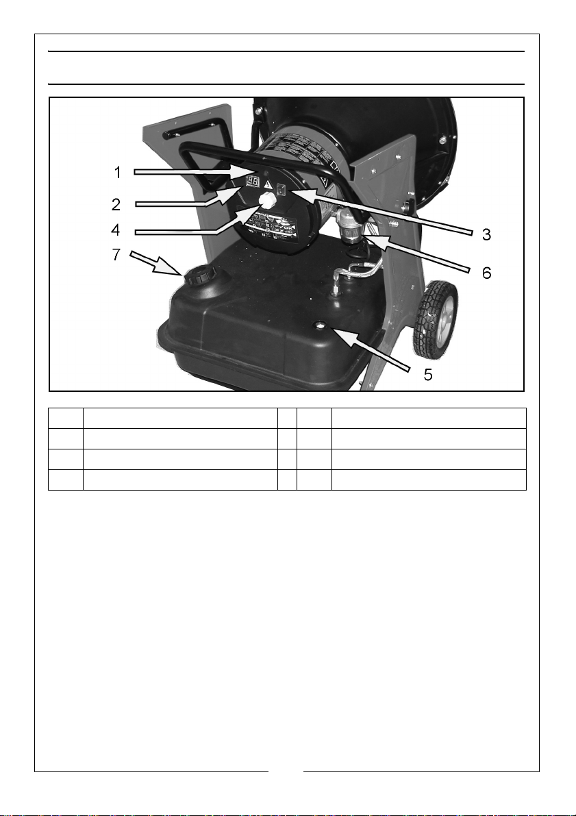
DEVIL IRD40B HEATER OVERVIEW
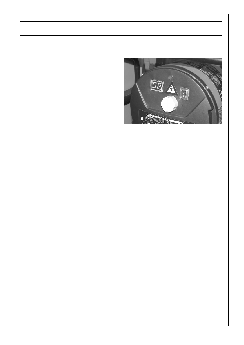
1
Power-on LED
2
Digital temperature display
3
Power switch
4
Temperature control knob
5
6
7
Fuel gauge
Fuel Filter
Fuel filler cap
FUNCTIONAL DESCRIPTION
A pump draws fuel from the tank and drives it to the burner under pressure.
Fuel is sprayed and atomised by the nozzle and then ignited by the burner
ignition device. A built-in radial blower provides combustion airflow while air
and fuel forms a combustion mixture. The flames heat up the front plate and
guard, thus releasing heat by radiation.
The burner pre-heater warms up the fuel before start-up and the postventilation function cools down the chamber after each use. No flue or
exhaust pipe is required as all combustion gasses are catalysed during
operation.
o
The unit can be tilted from 12 to 27
Parts & Service: 020 8988 7400 / E-mail: [email protected] or [email protected]
to direct heat at a particular target.
8
Page 9
SAFETY FEATURES
The unit is fitted with a temperature limit sensor, which is designed to turn the
heater off if the temperature should rise to an unsafe level. If the sensor is
tripped and the heater is turned off it may require a service. Once the
temperature falls back below the reset temperature, the heater should restart.
The heater is fitted with an electrical circuit breaker to protect the internal
components from damage. If the heater should fail to work, this fuse may
require checking by your dealer.
The heater is fitted with a tilt switch designed to turn the unit off immediately if
it should tip over beyond a pre-determined angle.
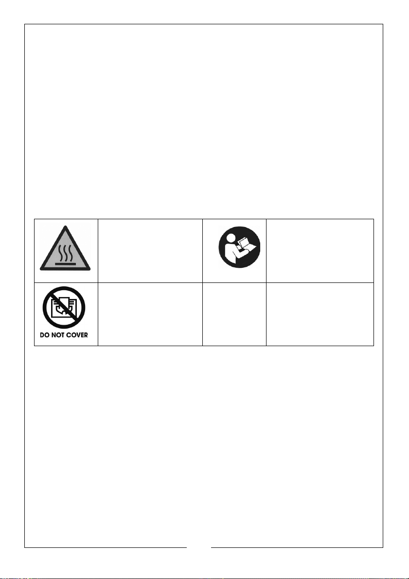
SAFETY SYMBOLS
The following symbols appear on the heater.
Hot Surface, do not
touch
Do not cover
Read these
instructions before use
9
Parts & Service: 020 8988 7400 / E-mail: [email protected] or [email protected]
Page 10
PREPARATION
UNPACKING & ASSEMBLY
When unpacking, check the heater for any damage that may have occurred
in transit and notify your Clarke dealer immediately should any be apparent.
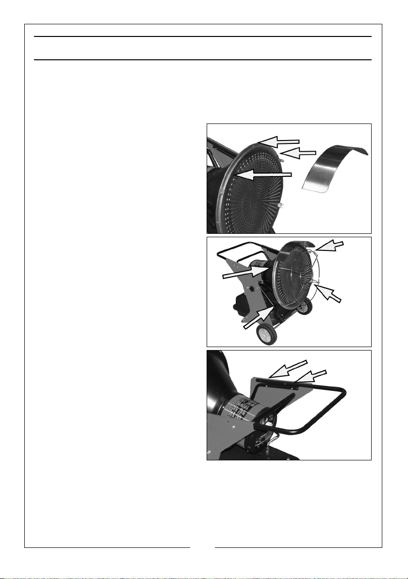
1. Fit the heat shield to the heater
body using three screws/nuts near
the top of the heater.
2. Fit the front grille to the heater
using four screws into the captive
nuts secured to the frame.
3. Fit the handle to the rear of the
heater using four bolts/nuts
supplied loose.
SUITABLE FUELS
Diesel or paraffin (kerosene) are the only fuels that should be used.
10
Parts & Service: 020 8988 7400 / E-mail: [email protected] or [email protected]
Page 11

FILLING THE FUEL TANK
Before re-fuelling, disconnect from
the power supply and allow to cool
down.
Fill the tank with clean, water-free
diesel oil. When refilling, inspect the
mesh filter inside the filler neck for any
trapped contamination and clean
out if necessary.
• When filling the heater, make
sure that the heater is level and
do not overfill. Use a funnel or can with a long filling spout.
Plug the heater into any suitably earthed mains power supply.
NOTE: In cold weather, condensation may develop in the tank if the tank
is empty. Before filling the fuel tank for the first time or after
extended storage periods, vent the fuel tank of any moisture or
condensation.
POSITIONING THE HEATER
The heater must be located on a
hard, level surface to minimise the risk
of accidental tipping over or running
forward. Chock the wheels if there is
any possibility of movement.
Set the heater angle of inclination by
loosening and re-tightening the
positioning knobs on either side to
achieve the required angle of tilt.
This heater should not be used in
habitable areas.
The heater should always be positioned well away from sources of airbourne
dust, as ingress of dust into the heater may cause it to malfunction. It will be
beneficial to shield the heater from a dusty work environment
MATERIAL CLEARANCES
It is important that the heater be positioned with at least 3 m clearance at the
front between the heater and any obstruction including walls or other
combustible surfaces. Always position the heater facing the centre of the
room. Never place any objects on, or against the heater.
Any equipment or workshop furniture should be a safe distance away as they
11
Parts & Service: 020 8988 7400 / E-mail: [email protected] or [email protected]
Page 12

could be adversely affected by heat. When the heater is in use, periodically
monitor any buildup of heat on nearby surfaces.
VENTILATION
The heater must only be installed in a room which is well ventilated. Ensure that
sufficient air is available for combustion via windows and doors, especially if
there will be people staying in the room for any length of time. Constant
occupation is not advised although the heater should be monitored
periodically.
Ventilation is essential to reduce the dangers of oxygen depletion.
HEATER OPERATION WITHOUT PEOPLE IN THE ROOM
Ensure that sufficient air is available via windows and doors for complete
3
combustion. The heated volume (m
10:1, and personnel should not stay permanently in the heated room.
HEATER OPERATION WITH PEOPLE REMAINING IN THE ROOM
If people are to remain in the room for any length of time, the heated volume
3
) /heat output (kW) must be at least 30:1. Air circulation must be ensured
(m
through windows and doors or permanent openings near the floor and
ceilings, whose total open area (m
output (kW).
)/ heat output (kW) ratio must be at least
2
) is at least 0.003 times the total heat
12
Parts & Service: 020 8988 7400 / E-mail: [email protected] or [email protected]
Page 13
OPERATION
HEATER START UP
1. Plug the heater into the mains
power supply.
2. Set the power switch to the ON
position.
• The ‘power-on’ LED will
illuminate and the digital
temperature display will show
the room temperature for up to
3 minutes.
• Turn the temperature control
knob to adjust the target temperature required. This setting will be
shown by the digital display.
NOTE: If the heater does not start up, the temperature control may be
set too low. Turn the control knob to a higher setting until the
heater starts. If the heater does not start, switch the power switch
off, then switch back on again. If the heater still does not start,
refer to fault-finding guide on page 13. Also check that the power
supply is correct.
HEATER SHUT DOWN & RE-STARTING
1. Set the power switch to the OFF position but do not unplug from the mains.
NOTE: When the heater is shut down, the fan will continue running for 3
minutes to expel hot air and cool the casing. For this reason the
heater should not be unplugged.
2. Only for extended shutdown should the heater be unplugged from the
mains supply.
3. If re-starting, wait 10 seconds after shutting off the heater before re-starting.
• Set the power switch to the ON position and follow the startup
procedure above.
4. Store the heater in a level position when filled, or fuel leakage may occur.
13
Parts & Service: 020 8988 7400 / E-mail: [email protected] or [email protected]
Page 14
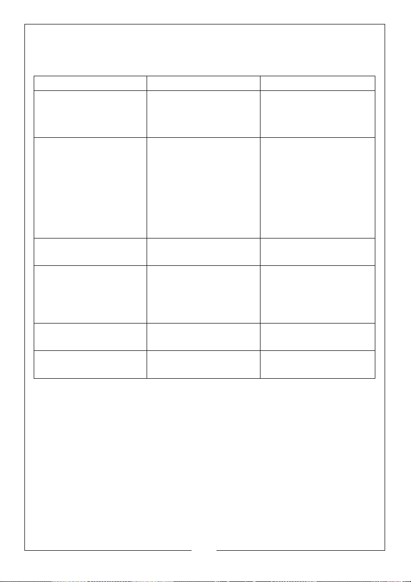
FAULT CODE DISPLAY
The digital display can show the following fault codes.
FAULT CODE CAUSE SOLUTION
FO:- Operation Error
F1:- Photocell Error
F2:- Temperature
Control Sensor error
F3:-Thermostat Error
LO
CH
1. Heater is switched on
before being plugged
in.
1. No fuel
2. Fuel is contaminated
3. Photocell is dirty or
damaged.
4. Fuel filter is dirty.
5. Ignition error
1. Damaged cable
2. Sensor is damaged.
1. Internal parts over
heating.
2. Anti-tilting sensor
activated.
1. External temperature
below -9
1. Air temperature over
55
o
C
o
C.
1. Disconnect from power
supply, switch off and
then plug in again
before switching on.
1. Switch off and refill the
tank.
2. Switch off, empty and
refill the fuel tank. Clean
the filter with clean fuel.
3.Contact your dealer.
4. Clean filter.
5. Contact your dealer.
1. Contact your dealer.
2. Contact your dealer.
1. Turn the heater off and
wait until it has cooled
down.
2. Reposition heater on a
level surface.
1. Wait for normal
temperature conditions
1. Wait for normal
temperature conditions
14
Parts & Service: 020 8988 7400 / E-mail: [email protected] or [email protected]
Page 15
CLEANING AND MAINTENANCE
WARNING: ALWAYS ENSURE THE HEATER HAS COOLED DOWN BEFORE
PERFORMING ANY MAINTENANCE TASKS
Before carrying out any adjustment or maintenance, ensure the heater is
switched OFF, disconnected from the mains supply, and has been given
adequate time to cool down.
CLEANING
1. Use a damp cloth wrung out in a solution of soapy water to clean the
exterior of the heater. Use household cleaners on difficult spots.
2. Never use abrasive cleaners as they may damage the paint finish.
3. The internal heating surfaces and combustion chamber of the burner
should be cleaned at least annually.
GENERAL MAINTENANCE
Correct maintenance is vital for smooth operation of the burner in order to
avoid wasting fuel and causing atmospheric pollution.
1. This heater should be inspected, cleaned and serviced annually by a
qualified service engineer. Unauthorised persons should not attempt to
carry out repairs of the burner components.
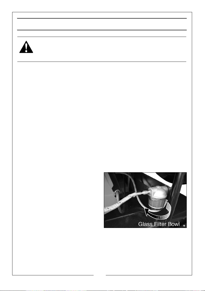
2. Replace the fuel filter cartridge if
water or dirt particles can be seen
in the glass filter bowl and at
approx 200 operating hours or as
needed.
15
Parts & Service: 020 8988 7400 / E-mail: [email protected] or [email protected]
Page 16
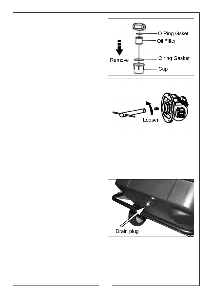
3. Burner nozzles should be cleaned
on replaced at least once per
heating season. Contaminated
fuel cause make this necessary
much sooner.
4. To clean dirt from the nozzle blow
compressed air through the nozzle
front. It may be necessary to soak
in clean diesel to help loosen any
remaining material.
5. Empty the tank and refill with fresh fuel if you suspect the fuel has become
contaminated.
In the event of damage or broken components, replacements are available
from Clarke Parts & Service.
LONG TERM STORAGE
1. For long term storage, unscrew
the drain plug and drain out any
remaining fuel. Use a small
amount of fresh fuel to rinse and
swirl the fuel in the tank and
empty completely. Avoid storing
leftover diesel in the tank during
the summer season as old fuel
can be damaging to the heater
components.
2. Always store the heater in a dry,
well ventilated area away from combustible materials. Cover the heater
and keep dry and dust free.
16
Parts & Service: 020 8988 7400 / E-mail: [email protected] or [email protected]
Page 17
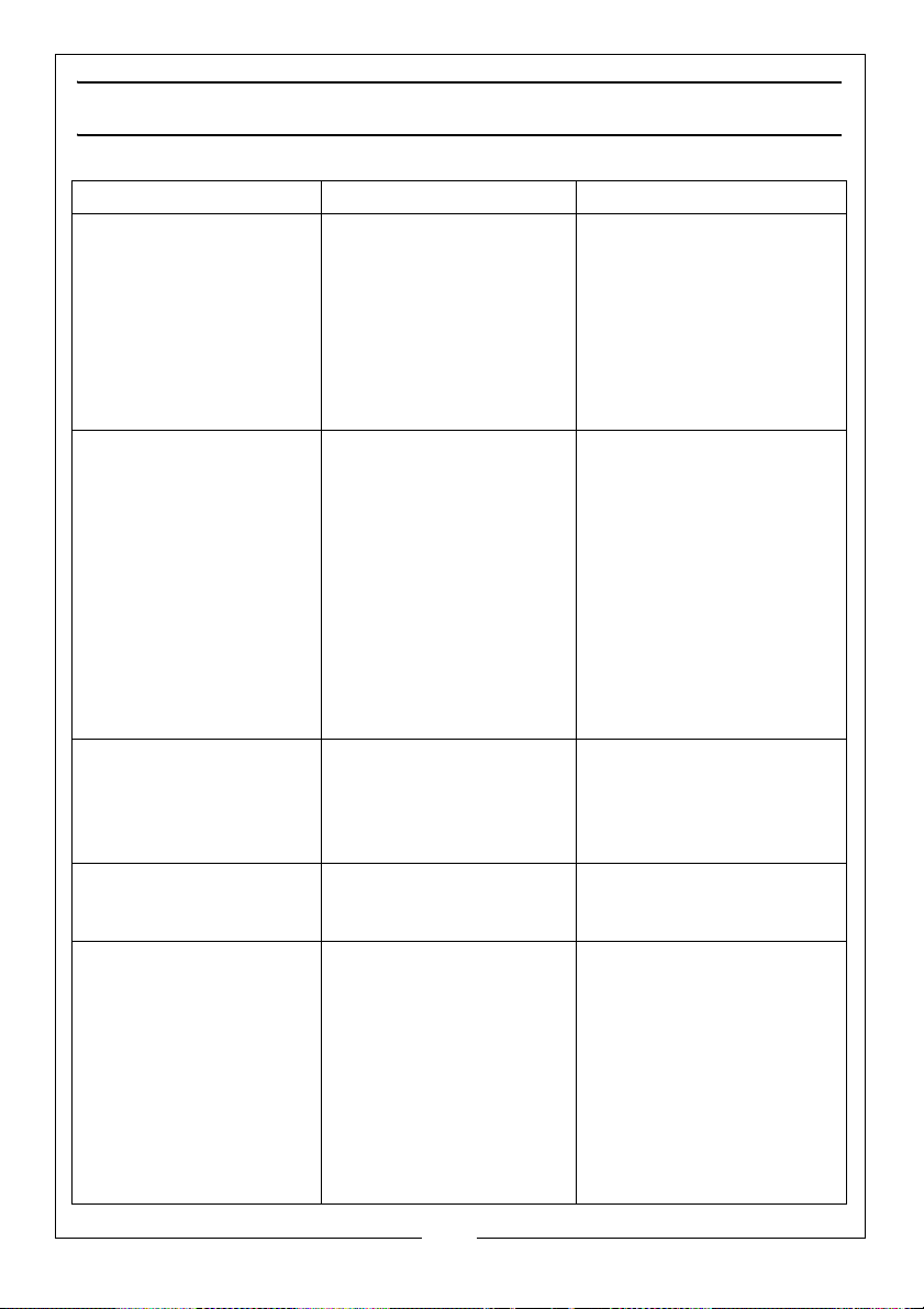
FAULT FINDING
Problem Cause Solution
Heater fires but shuts off
after a short period of
time.
Heater will not operate 1. No fuel in tank
Fan does not operate
when heater is switched
on.
Poor combustion and/or
excessive soot production.
Heater does not turn on
and the lamp does not
light.
1. Dirty fuel filter
2. Nozzle is dirty
3. Photocell lens is dirty
4. Photocell not installed
properly.
5. Photocell defective
6. Bad connection
between PCB and
photocell
2. Corroded spark plug or
incorrect plug gap
3. Dirty fuel filter
4. Dirty nozzle
5. Moisture in fuel/tank
6. Bad electrical
connection between
transformer and PCB
7. Igniter wire not
connected to sparkplug
8. Defective igniter
1. Thermostat is set too low
2. Broken electrical
connection between
main PCB and motor.
1. Dirty fuel filter
2. Poor quality fuel.
1. Temperature limit sensor
has overheated.
2. No electrical power
3. Fuse blown
4. Bad connection
between temperature
limit sensor and PCB.
1. Clean/replace fuel filter
2. Clean/replace nozzle
3. Clean photocell
4. Adjust photocell position
5. Return to dealer for new
photocell
6. Ask dealer to check
wiring connections
1. Fill tank with fresh fuel.
2. Ask dealer to clean/re gap/replace spark plug
3. Clean/replace fuel filter
4. Ask dealer to clean/
replace nozzle.
5. Rinse out fuel tank with
clean, fresh fuel.
6. Return to dealer.
7. Return to dealer for repair.
8. Return to dealer for repair.
1. Turn the thermostat to a
higher setting
2. Ask dealer to check all
electrical connections.
1. Clean/replace fuel filter
2. Check that fuel is not
contaminated or old.
1. Set the power switch to
off and allow the heater
to cool for 10mins before
switching back on.
2. Check the power cable
for good connection.
Test the power supply.
3. Return to dealer for repair.
4. Return to dealer for repair.
17
Parts & Service: 020 8988 7400 / E-mail: [email protected] or [email protected]
Page 18
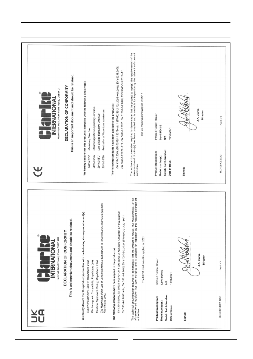
DECLARATIONS OF CONFORMITY
18
Parts & Service: 020 8988 7400 / E-mail: [email protected] or [email protected]
Page 19
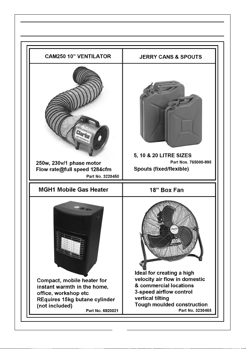
ADDITIONAL CLARKE PRODUCTS
19
Parts & Service: 020 8988 7400 / E-mail: [email protected] or [email protected]
Page 20

 Loading...