

Page 1
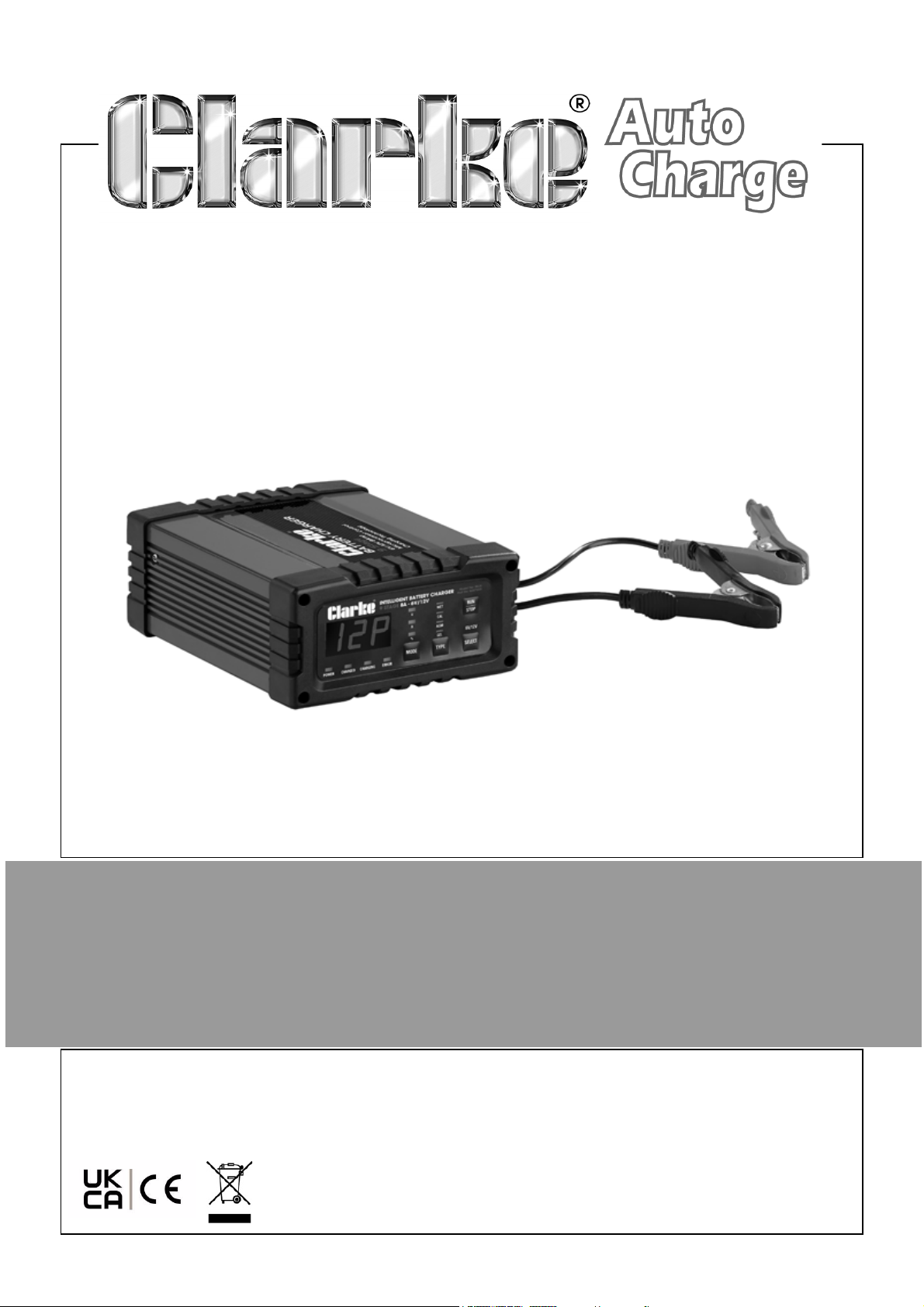
6V/12V INTELLIGENT BATTERY CHARGER
MODEL NO: IBC8
PART NO: 6267035
OPERATION & MAINTENANCE
INSTRUCTIONS
ORIGINAL INSTRUCTIONS DL1024 Rev 1
Page 2

INTRODUCTION
Thank you for purchasing this CLARKE Battery Charger.
Please read this manual thoroughly, before attempting to operate this product and
carefully follow all instructions given.
It is vitally important that ALL precautions are taken, as specified, which will not only
provide protection for yourself and that of others around you, but will also ensure that
the battery charger will give you long and satisfactory service.
GUARANTEE
This CLARKE product is guaranteed against faulty manufacture for a period of 12
months from the date of purchase. Please keep your receipt as proof of purchase.
This guarantee is invalid if the product is found to have been abused or tampered
with in any way, or not used for the purpose for which it was intended.
Faulty goods should be returned to their place of purchase, no product can be
returned to us without prior permission.
This guarantee does not effect your statutory rights.
ENVIRONMENTAL RECYCLING POLICY
Through purchase of this product, the customer is taking on the obligation
to deal with the WEEE in accordance with the WEEE regulations in relation
to the treatment, recycling & recovery and environmentally sound disposal
of the WEEE.
In effect, this means that this product must not be disposed of with general
household waste. It must be disposed of according to the laws governing Waste
Electrical and Electronic Equipment (WEEE) at a recognised disposal facility.
2
Parts & Service: 020 8988 7400 / E-mail: [email protected] or [email protected]
Page 3
OVERVIEW
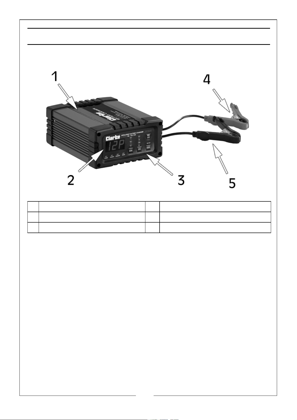
1 Battery Charger Unit 4 Charging Clamp Positive (Red)
2 LCD Display Screen 5 Charging Clamp Negative (Black)
3 Control Buttons
The IBC8 is designed for charging most types of 6V & 12V lead-acid, GEL, MF
(Maintenance Free), Calcium and AGM (Absorbed Glass Mat) batteries.
DO NOT use this product to charge other type of batteries like Nickel Cadmium
(NiCad), Nickel-Metal Hydride (Ni-MH), Lithium-Ion, Dry Cell etc.
3
Parts & Service: 020 8988 7400 / E-mail: [email protected] or [email protected]
Page 4
ELECTRICAL CONNECTIONS
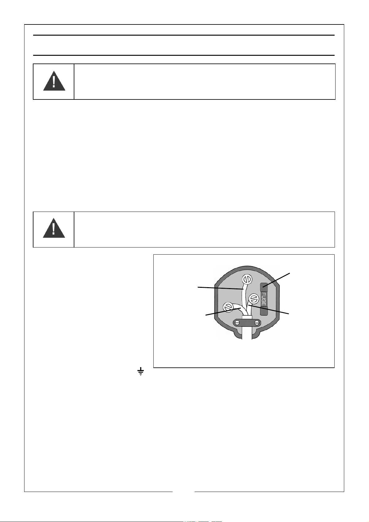
Plug must be BS1363/A approved.
Always fit
Ensure that the outer sheath of
Neutral
(Blue)
Live
(Brown)
Earth
(Green and
a 3 Amp
the cable is firmly held by the clamp
fuse.
Yellow)
WARNING! READ THESE ELECTRICAL SAFETY INSTRUCTIONS
THOROUGHLY BEFORE CONNECTING THE PRODUCT TO THE
MAINS SUPPLY.
Before switching the product on, make sure that the voltage of your electricity supply
is the same as that indicated on the rating plate. This product is designed to operate
on 230VAC 50Hz. Connecting it to any other power source may cause damage.
This product may be fitted with a non-rewireable plug. If it is necessary to change the
fuse in the plug, the fuse cover must be refitted. If the fuse cover becomes lost or
damaged, the plug must not be used until a suitable replacement is obtained.
If the plug has to be changed because it is not suitable for your socket, or due to
damage, it should be cut off and a replacement fitted, following the wiring
instructions shown below. The old plug must be disposed of safely, as insertion we
would emphasise the electrical hazard.
WARNING: WIRES IN THE MAINS LEAD ARE COLOURED IN
ACCORDANCE WITH THE FOLLOWING CODE:
GREEN/YELLOW = EARTH, BLUE = NEUTRAL, BROWN = LIVE.
We strongly recommend that this machine is connected to the mains
supply via a Residual Current Device (RCD).
If in any doubt, consult a qualified electrician. DO NOT attempt any repairs yourself.
•The BLUE wire must be
connected to the
terminal marked N or
coloured black.
•The BROWN wire must
be connected to the
terminal marked L or
coloured red.
•The YELLOW AND
GREEN wire must be
connected to the
terminal marked E or
or coloured green.
4
Parts & Service: 020 8988 7400 / E-mail: [email protected] or [email protected]
Page 5

SAFETY PRECAUTIONS
WARNING: ALWAYS SWITCH OFF THE CHARGER WHEN
CONNECTING OR DISCONNECTING LEADS TO AVOID SPARKING AS
HIGHLY INFLAMMABLE HYDROGEN GAS CAN BE RELEASED IN THE
PROCESS OF BATTERY CHARGING
PLEASE READ BEFORE USING THIS UNIT
1. Batteries can generate explosive gases during normal operation. ALWAYS use in
well ventilated area.
2. DO NOT smoke, strike a match or cause a spark in the vicinity of the battery or
engine. Avoid explosive gas, flames and sparks.
3. Remove all personal jewellery, such as rings, bracelets, necklaces and watches
while working with a vehicle battery. These items may produce a short circuit and
could cause severe burns.
4. Be extra cautious to reduce the risk of dropping a metal tool onto the battery. It
may spark or short circuit the battery or other electrical hardware which may
cause an explosion or fire.
5. Wear complete eye protection, hand and clothing protection. AVOID touching
eyes while working near a battery.
6. Study all battery manufacturers specific precautions, such as removing or not
removing cell caps while charging and recommended rates of charge.
7. Clean battery terminals before connection with the charger. Be careful to keep
corrosion from coming in to contact with eyes.
8. When it is necessary to remove the battery from the vehicle to charge, always
remove grounded terminal from the battery first. Make sure all accessories in the
vehicle are switched off in order to prevent an arc.
9. This charger is NOT intended to supply power to an extra low voltage electrical
system or to charge dry cell batteries. Charging dry cell batteries may cause the
battery to burst and cause injury to person or property.
10. NEVER charge a frozen, damaged, leaking or non rechargeable battery.
11. If battery electrolyte contacts skin or clothing, wash immediately with soap and
water. If electrolyte enters your eye, immediately flood eye with running clean
cold water for at least 15 minutes and seek medical attention immediately.
12. DO NOT place the charger in the engine compartment, near moving parts or near
the battery. Place as far away from them as the cable permits. NEVER place the
charger directly above the battery being charged, gases or fluids from the battery
will corrode and/or damage the charger.
5
Parts & Service: 020 8988 7400 / E-mail: [email protected] or [email protected]
Page 6
13. DO NOT cover the charger while charging.
14. DO NOT expose to rain or wet conditions.
15. Connect and disconnect the DC output connections only after disconnecting the
charger from the mains power supply.
16. Use of an attachment not recommended or sold by the manufacturer may result in
a risk of fire, electric shock or injury to persons.
17. DO NOT overcharge batteries by selecting the wrong charge mode.
18. To reduce the risk of damage to the electric plug and cord, pull by the plug rather
than the cord when disconnecting charger from mains power supply.
19. To reduce risk of electric shock, unplug charger from mains power supply before
attempting any maintenance or cleaning.
20. Operate with caution if the charger has received a direct hit of force or been
dropped. Have it checked and repaired if damaged.
21. NEVER attempt any repairs yourself. If you have a problem with your charger
contact your local CLARKE dealer or contact [email protected]
22. When charging is complete, ensure that the vehicle battery leads are secured to
the proper terminals which should be clean, and lightly smeared with petroleum
jelly to prevent corrosion. Finally, re-check the electrolyte level.
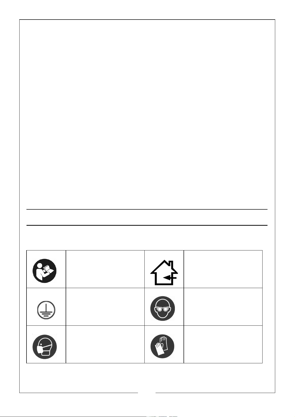
SAFETY SYMBOLS
Before Use, Read The
Instructions Fully
Class I Appliance Wear Eye Protection
For Indoor Use Only
Wear a Protective Mask Wear Protective Gloves
6
Parts & Service: 020 8988 7400 / E-mail: [email protected] or [email protected]
Page 7

PREPARATION
1. It may be necessary to remove the battery from a vehicle to charge it.
• ALWAYS remove the grounded terminal from the battery first.
• Ensure all accessories in the vehicle are switched off to prevent sparking.
2. Clean the battery terminals. Be careful to keep any corrosive matter from coming
in contact with eyes.If corrosive matter enters your eye, immediately flood eye
with running clean cold water for at least 15 minutes and seek medical attention
immediately.
3. If the battery can be topped up, add distilled water to each cell until the battery
acid reaches the level specified by the battery manufacturer. This helps remove
unwanted gas from the cell. DO NOT overfill. For a battery without cell caps,
follow the manufacturer's instructions.
4. Study all the battery manufacturer's specified precautions: for example, removing
or not removing cell caps while being charged and recommended rates of charge.
5. Refer to the vehicle manual and battery rating plate to find the voltage of the
battery and make sure that the output is set to the correct voltage.
6. If the charger has adjustable charge rate, charge the battery initially at the lowest
rate.
CHARGER LOCATION
1. Place the charger as far away from the battery as possible.
2. DO NOT position the charger above the battery during the charging procedure.
Gases from the battery may corrode and damage the charger.
3. DO NOT let battery acid drip on the charger when reading a hydrometer for
specific gravity or when you fill the battery.
4. DO NOT use the charger in an enclosed space with reduced airflow.
7
Parts & Service: 020 8988 7400 / E-mail: [email protected] or [email protected]
Page 8
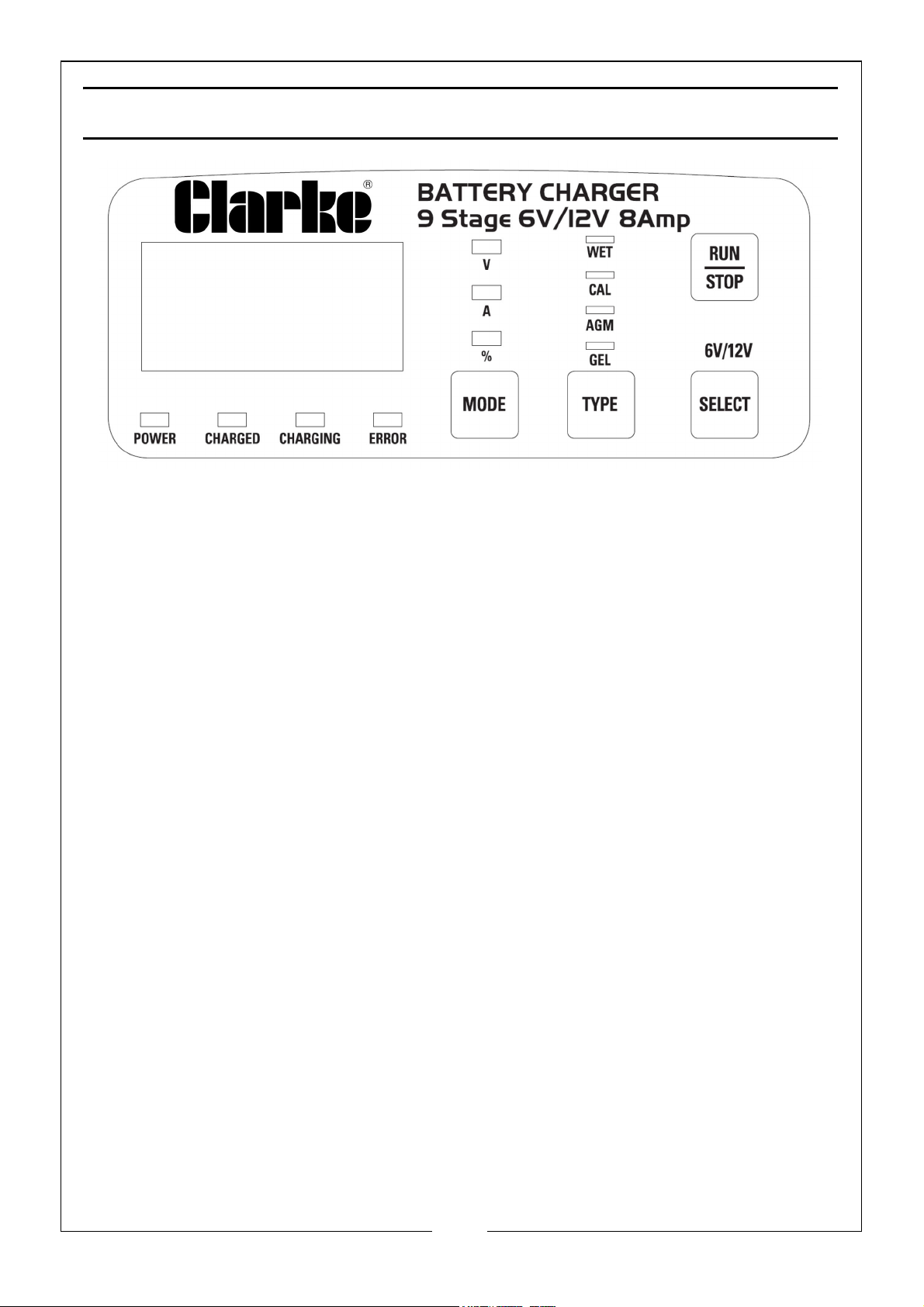
CONTROLS
BATTERY CHARGE INDICATORS:
1. Power - A green LED illuminates to confirm power is being supplied to the battery
charger. If it is the only LED illuminated, the charger is in “Maintain Mode”.
2. Charged - A green LED illuminates to signal that the battery is fully charged and
may be disconnected for use. It left “on charge”, the LED will turn off after 1 hour
and only the green power LED will stay illuminated.
3. Charging - An amber LED illuminated to signal that the charger is charging the
battery.
4. Error - A red LED illuminates if the connection is wrong, the incorrect battery
voltage is selected or the battery is faulty. In each of these instances, the charging
of the battery will not proceed.
NOTE: The LCD will show Er1, if the clamps are “shorted”, loose or poorly connected,
if the battery voltage is less that 0.5V, or if the battery voltage is >15.5V (for
12V Mode) or >7.8V (for 6V Mode).
NOTE: The LCD will show Er2, if the battery is damaged or unable to be charged.
NOTE: The LCD will show Er4, if the clamps are connected incorrectly, i.e. reverse
polarity (+ve clamp to -ve battery terminal and -ve clamp to +ve battery
terminal).
NOTE: Batteries with a battery voltage below 10.5V may be permanently damaged.
It is recommended that batteries not be discharged to below 10.5V.
MODE:
1. V - Displays the battery voltage prior to pressing RUN, and displays the actual
charging voltage during each of the charging cycles.
8
Parts & Service: 020 8988 7400 / E-mail: [email protected] or [email protected]
Page 9

NOTE: Due to the pulse voltages applied during the desulphation mode, the
displayed voltage may constantly change and cycle from 0 volts to 16 volts.
2. A - Displays the current in Amps (A) being applied to the battery during charging.
NOTE: If 0.0 is displayed, a very small current (A) is being applied to achieve
maximum charge.
3. % - Displays the charge condition of the battery as a percentage of full charge.
TYPE:
1. WET - Conventional automotive starting lead acid batteries generally have six
cells, each containing lead plates and sulphuric acid. These batteries provide a
high current output in short bursts and are ideally suited to automotive starting
applications.
2. CAL - Calcium batteries are essentially the same as lead acid batteries. However,
the addition of small amount of calcium to the lead plates means calcium batteries
have low water loss, low self discharge characteristics, lower internal resistance
which provides a small increase in CCA performance and a higher charge rate
acceptance compared to standard lead acid batteries.
3. AGM - Absorbed Glass Mat batteries are a type of valve regulated lead acid
battery designed to wick the battery electrolyte between the battery plates. AGM
batteries contain only enough liquid to keep the mat wet with the electrolyte and
if the battery is broken no free liquid is available to leak out. The advantages of
this type is that the electrolyte does not need topping up, nor can it be. They can
be operated in any position and they have a very low gas release during charging.
these batteries are however, sensitive to overcharging and require a different
charge algorithm than standard lead acid batteries.
4. GEL - GEL batteries are a type of valve regulated lead acid battery and are
typically more costly and do not offer the same power capacity as AGM batteries
of a similar size. The GEL cell battery excels in slow discharge rates and higher
ambient operating temperatures. GEL cell batteries must be recharged correctly or
the battery will suffer premature failure.
RUN/STOP
After selecting the above parameters pressing the RUN/STOP button starts and stops
the charger. After commencing a charge cycle, use this button to stop the charger to
change any of the charge parameters, e.g. current or chemistry. Recommence the
charge cycle by pressing the button.
9
Parts & Service: 020 8988 7400 / E-mail: [email protected] or [email protected]
Page 10

FEATURES
MICROPROCESSOR TECHNOLOGY
The latest technology in battery chargers converts 240VAC to DC charging power
using electronic components, unlike traditional battery chargers that rely on large
heavy transformers. This allows the charger to be lightweight and compact without
sacrificing performance. to increase safety, polarity protection prevents the output
leads from sparking due to accidental reverse connection of short circuit.
MAXIMISING BATTERY PERFORMANCE
Your battery will perform better when charged using a 9 stage charger, maximising
the output from the battery.
MAXIMISE BATTERY LIFE
Batteries used regularly will last longer when charged using a 9 stage charger, saving
you money on expensive batteries.
AUTOMATIC MICROPROCESSOR CONTROL
The charger can be left connected to the battery without risk of overcharging. Once
the battery is full, the charger will automatically monitor the battery and top up the
battery when required, ensuring it is always ready for use.
BATTERY CHEMISTRY SELECTION
The charger includes intelligent chemistry technology to provide the most suitable
charge profile for the applicable chemistry.
1. WET (Lead Acid) - Bulk/Absorption 14.7V, Recondition 15.8V.
Conventional automotive “starting” batteries provide a high current for short
periods and are ideally suited to automotive starting applications.
2. GEL/AGM - Maximum Voltage of 14.2V = GEL and 14.4V = AGM. GEL and
AGM batteries are types of valve regulated lead acid (VRLA) batteries and due to
their design can be orientated in any position and exhibit very low gas release
during charging. These batteries do not allow the replenishment of electrolyte
levels and are sensitive to overcharging, requiring lower charge rates.
3. Calcium - Bulk Absorption 14.7V, Equalisation/Recondition 15.8V.
Calcium batteries are essentially the same as lead acid batteries, however the
inclusion of calcium significantly reduces fluid loss, provides much lower self
discharge characteristics and lowers internal resistance, which increase its cold
cranking current (CCA) performance. To ensure optimal battery condition and to
maintain a maximum state of charge, a special profile is needed to balance cell
voltages and/or remove unique sulphation barriers caused when calcium batteries
have a high demand or are left discharged for a number of days.
10
Parts & Service: 020 8988 7400 / E-mail: [email protected] or [email protected]
Page 11

ADJUSTABLE CHARGE VOLTAGE
The chargers output voltage (V) can be selected to suit the output voltage of the
battery being charged, i.e. 6V or 12V.
LIQUID CRYSTAL DISPLAY (LCD) - VOLTAGE (V), CURRENT (A)
& PERCENTAGE CHARGED (%)
The LCD provides three selectable display outputs. The LED indicators on the fascia
highlight the selected characteristic being monitored and displayed.
DE-SULPHATION FUNCTION
This feature provides a stepped or pulsed voltage to help remove the suphation of
plates which can occur when batteries are left discharged for prolonged periods.
NOTE: If the battery is unable to be recovered (i.e. the suphation of the plates is too
severe), the battery charger will display the error message Er2.
RECONDITIONING
When the battery has been left unattended for a prolonged period, the suphation of
the plates may be severe for stage 2: De-sulphation cycle to adequately clean plates.
In these instances, the ANALYSIS stage will identify that sulphation of the plates still
exists and an additional RECONDITION stage will provide a more concerted effort in
an attempt to recover the battery.
For calcium batteries, the RECONDITION stage will balance any differences in cell
voltage, and repair cell stratification of the calcium battery.
NOTE: The inclusion of a RECONDITION stage may significantly increase the charge
time (up to 48 hours).
LIQUID CRYSTAL DISPLAY
A liquid crystal display (LCD) provides a clear, easy to read display.
CELL EQUALISATION
The charger provides a low voltage PRE-CHARGE function at a low current to allow
the battery cells to equalise.
OVER TEMPERATURE CONTROLS
When the internal temperature of the charger reaches 50c, sensors reduce the output
current to minimise damage due to overheating.
NOTE: This feature may cause an increased charge time due to interruptions to the
charge cycle.
AUTOMATIC MULTI-CYCLE CONDITIONING
If the battery will not hold a charge at the completion of the first cycle, the 9 stages
of the cycle are automatically repeated for up to a further two times to achieve the
11
Parts & Service: 020 8988 7400 / E-mail: [email protected] or [email protected]
Page 12
battery’s maximum charge condition. This minimises the need to monitor and repeat
the charge cycle if the condition of the battery is not optimum after the first charge
cycle.
NOTE: This feature may significantly increase the charge time (up to 48 hours).
OPERATION
PLACEMENT/MOUNTING
The charger is designed for indoor use only. The position selected for the charging of
the battery must be cool, dry, clean and well ventilated, away from flammable goods
and ignition sources.
NOTE: When utilised in caravans, motorhomes, 4WD’s or similar, the charger should
be placed or mounted in a well ventilated location and protected from rain,
water or moisture at all times.
Connection to the mains supply must be in accordance with national wiring rules and
regulations.
To minimise TV/Radio interference, position the charger well away from any TV, radio,
antenna and antenna cables.
CHARGING INSTRUCTIONS
BATTERY MANUFACTURER RECOMMENDATIONS
Before using the battery charger, study the battery manufacturers recommendations,
rates of charge and any particular conditions to the battery being charged.
CHECK THE ELECTROLYTE LEVEL
Prior to charging the battery, remove the vent caps and check the electrolyte level.
NOTE: For batteries without cell caps, follow the battery manufacturers maintenance
and charging instructions.
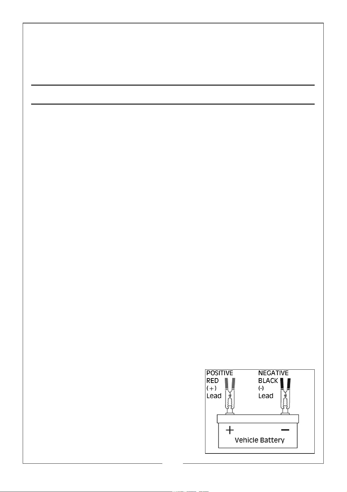
CONNECTION
a. Connection with Battery out of the Vehicle
Connect the POSITIVE (RED) lead/battery
clamp from the charger to the POSITIVE battery
post. Connect the NEGATIVE (BLACK) lead/
battery clamp from the charger to the NEGATIVE
battery post.
NOTE: The POSITIVE terminal of a battery is
defined by the colour RED and may be
presented by POS, P or (+). The
12
Parts & Service: 020 8988 7400 / E-mail: [email protected] or [email protected]
Page 13
NEGITIVE terminal of a battery is defined by the colour BLACK and may be
represented by NEG, N or (-).
Wiggle or swivel the clamps several times - this action ensures integrity of the
connection and minimises sparks/arcing.
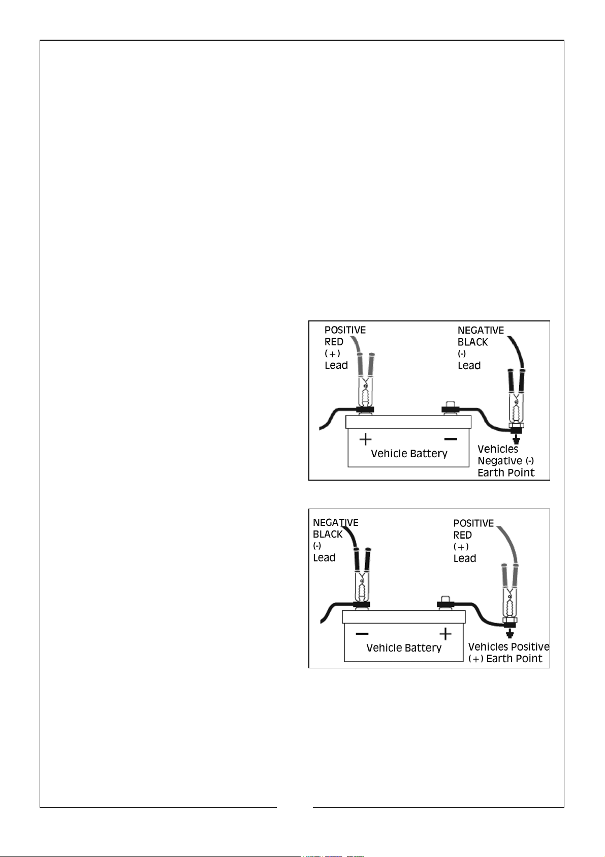
b. Connection with the Battery Mounted in the Vehicle
Determine if the vehicle is POSITIVELY (+) or NEGITIVELY (-) earthed.
NOTE: The battery terminal NOT connected to the chassis MUST be connected to
the battery charger first. The second clamp from the battery charger must be
connected to the chassis away from the battery and fuel lines.
Refer to the following guides for correct battery clamp connection sequence:
Negatively Earthed (Most Vehicles)
NOTE: Negatively earthed vehicles usually have a cable (usually BLACK or GREEN)
connecting the negative battery terminal to the vehicles chassis.
Connect the POSITIVE (RED) lead/
battery clamp from the battery charger
to the Positive (+) battery terminal.
Connect the NEGATIVE (BLACK) lead/
battery clamp from the battery charger
to the vehicles chassis - away from the
fuel lines or moving parts.
Positively Earthed
Connect the NEGATIVE (BLACK) lead/
battery clamp from the battery charger
to the Negative (-) battery terminal.
Connect the POSITIVE (RED) lead/
battery clamp from the battery charger
to the vehicles chassis - away from the
fuel lines or moving parts.
CONNECT TO MAINS POWER
Connect the battery charger to a 230V mains powered socket, turn on the mains
power and press the “ON/OFF” button. The power LED and LCD will illuminate to
confirm that the battery charger is receiving power.
13
Parts & Service: 020 8988 7400 / E-mail: [email protected] or [email protected]
Page 14

SELECT THE CHARGE VOLTAGE
Press the “SELECT” button to select the appropriate battery voltage - 6V or 12V. The
LCD will display 6P or 12P.
SELECT THE BATTERY CHEMISTRY
Press the “TYPE” button to select the appropriate battery chemistry and
technology - WET, CALCIUM,AGM or GEL.
NOTE: If the battery charger does not detect a correctly connected battery, or
detects an incorrect battery voltage, Er1 or Er4 code will display on the LCD and
charging will not commence.
CHARGING
The CHARGING LED will illuminate and the voltage being supplied to the
battery is displayed in the LCD window.
MONITORING
During charging cycles, voltage (V), current (A) or percentage charged (%) can be
displayed on the LCD by pressing the “MODE” button. After
approximately 5 seconds, the LCD display will revert to voltage (V).
NOTE: During the charge cycle, voltages up to 15.8V (7.9V in 6V mode) may be
observed, this is deemed normal.
CHARGING COMPLETE
Once charging of the battery is complete, the charging LED will extinguish, the
charged LED will illuminate and FUL will display in the LCD window for 2
minutes. at this point, the red LCD will extinguish and the green charged and power
LED’s will continue to illuminate to show that the battery is charged.
NOTE: If at any stage during charging, the battery is found to be faulty, Er2 will be
displayed and charging will terminate.
Once charging is completed and FUL us displayed in the LCD window, BEFORE
removing the battery clamps, press the ON/OFF button to turn the battery charger
“OFF”, switch the mains supply power to OFF and disconnect (Unplug) the battery
charger from the supply socket outlet.
NOTE: If left “ON” and connected to main supply, the charger will monitor the
battery and maintain the battery ready for use - preventing slow discharge
over time, which is detrimental to lead acid batteries.
DISCONNECTION - BATTERY OUT OF THE VEHICLE
Remove the NEGATIVE (BLACK) connection first, then remove the POSITIVE
(RED) terminal clamp.
DISCONNECTION - BATTERY MOUNTED IN THE VEHICLE
Remove the chassis connection first, then remove the other battery clamp from the
battery terminal.
14
Parts & Service: 020 8988 7400 / E-mail: [email protected] or [email protected]
Page 15

RECHECK THE ELECTROLYTE LEVELS
Recheck the electrolyte levels and top up if required - this is especially
necessary for Calcium type batteries.
CARE & MAINTANENCE
This battery charger requires minimal maintenance. As with any appliance or tool, a
few common sense rules will prolong its working life.
WARNING: ALWAYS BE SURE THE CHARGER IS UNPLUGGED
BEFORE PERFORMING ANY MAINTENANCE OR CLEANING. ANY
REPAIRS MUST BE DONE BY A QUALIFIED SERVICE TECHNICIAN.
1. Wind up the leads when not in use. Examine the leads at regular intervals for
damage and have them replaced if necessary.
Clean the case and leads if necessary with a moist cloth and clean any corrosion from
the clamps with a solution of water and baking soda.
SPECIFICATIONS
Model Number IBC8
Input voltage / Current 230V, 50Hz
Battery charging voltages: 6V & 12V
Power 120W Max
Output current 6V: 4A 12V:8A
Charging steps 9 steps, (smart charger)
Charging Battery Capacity 160 AH
IP Rating IP40
Operating Temperature Range -20 to 50°C
Dimensions (D x W x H) 167mm x 135mm x 65mm
Power Cable Length 1.80m
Charging Clamp Cable Length 1.80m
Ring Terminal Cable Length 1.80m
Weight 1.1 kg
15
Parts & Service: 020 8988 7400 / E-mail: [email protected] or [email protected]
Page 16
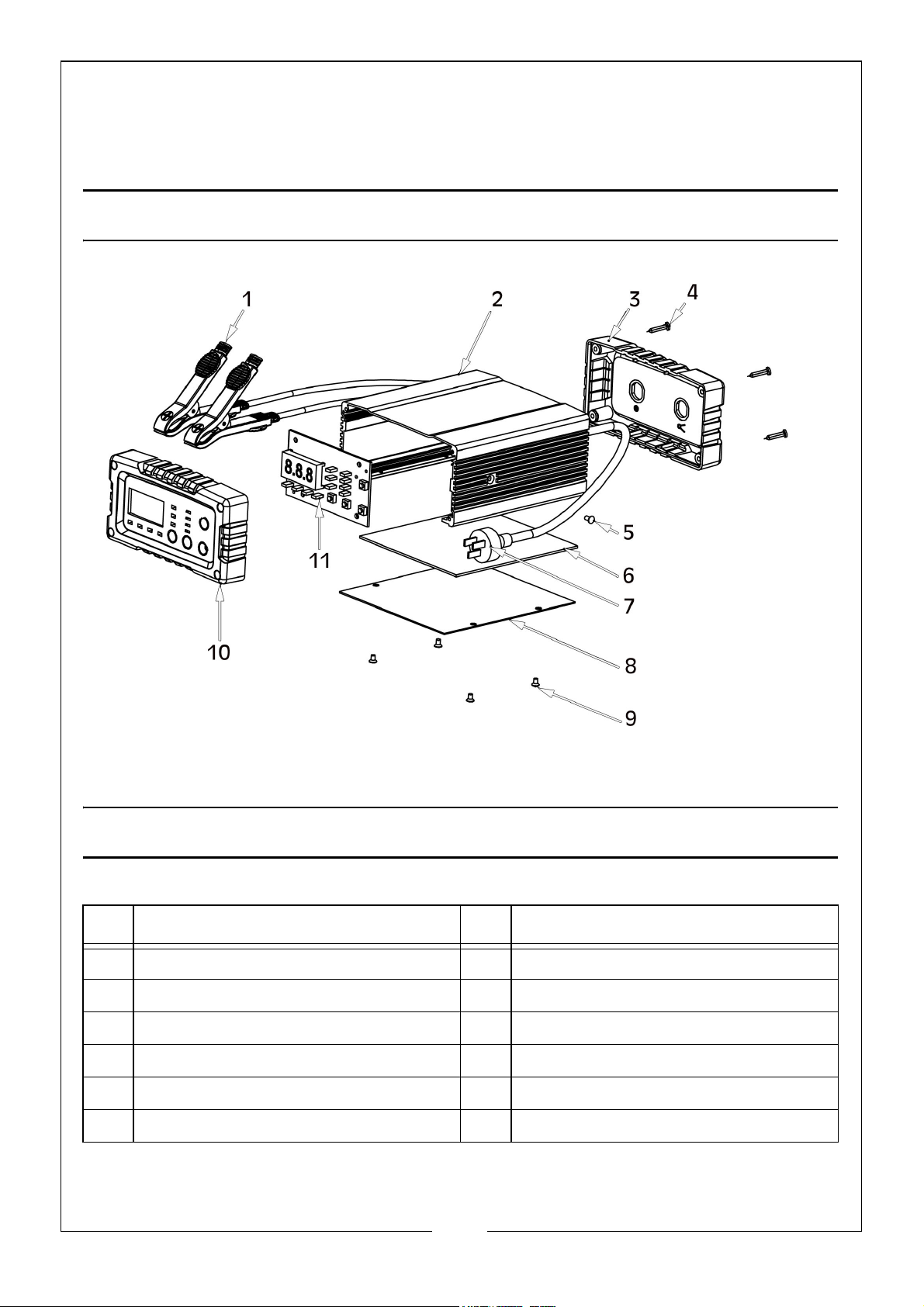
PARTS DIAGRAM
PARTS LIST
NO DESCRIPTION NO DESCRIPTION
1 Charging Cables & Clamps 7 Power Cable
2 Aluminium Case 8 Bottom Case Panel
3 Back Panel 9 Screw, M3 x 5
4 Screws, ST3 x 10 10 Front Panel
5 Screws, M3 x 14 11 Display Board
6 Printed Circuit Board Assembly
16
Parts & Service: 020 8988 7400 / E-mail: [email protected] or [email protected]
Page 17
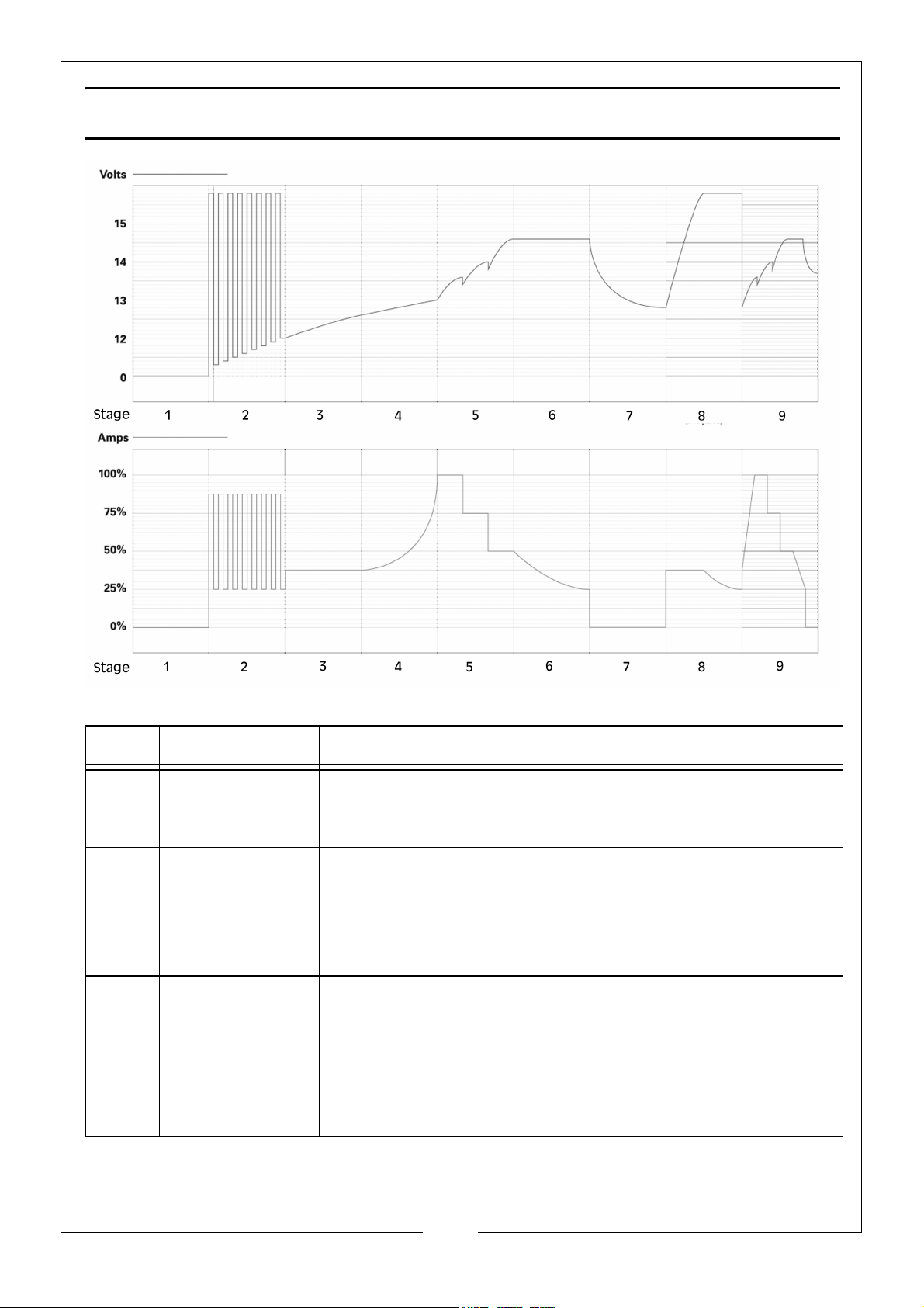
CHARGE CYCLES
STAGE FUNCTION DESCRIPTION
1 Diagnosis To determine whether the battery is defective.
Charging will not proceed if the battery voltage is <0.5V
and an error code will be displayed on the LCD.
2 Desulphation This stage provides a stepped or pulsed voltage to help
remove the sulphation of plates which can occur when the
battery is left discharged for prolonged
periods. It also stabilises electrolytic balance and
minimises excessive battery temperature.
3 Pre-Charge A low voltage and current is used to slowly increase battery
condition and further improve electrolytic consistency
which can become uneven due to day to day use.
4 Soft Start At an increased voltage, the current is slowly increased
over time to control heat, reduce gassing and minimise bat-
tery stress.
17
Parts & Service: 020 8988 7400 / E-mail: [email protected] or [email protected]
Page 18

S
TAGE FUNCTION DESCRIPTION
5Bulk Charge
(Constant
Current)
Initially, maximum current is applied to the battery how-
ever, the three phases of the stage reduce the time to
charge, control electrolytic loss and enhance battery health
and life.
CC1 CC1 - Charging at maximum current.
CC2 CC2 - Current is reduced.
CC3 CC3 - Current is further reduced for improved charge whilst
minimising electrolyte loss and excess
temperature.
6 Absorption (Con-
stant
Voltage)
Applying an even higher voltage whilst reducing current
over time ensures the battery is topped up but not over
charged
7 Analysis The charger conducts an analysis of the battery over a
period of time to determine the battery discharge rate.
Based on the battery performance, the battery charger will
recommence charging or move to the next stage.
8 Recondition
(High Voltage
Repair)
The recondition phase applies maximum voltage to maxi-
mise battery condition and further repair and clean battery
plates. This may be required following significant dis-
charge, for batteries with uneven cell capacity or, to allevi-
ate acid stratification when
calcium batteries are left discharged for more than a couple
of days.
NOTE: The battery charger will assess the condition of
the battery and may not perform this function.
9 Maintain The battery charger monitors the battery voltage and
recommences the charge sequence when the
voltage drops to 12.8V (or 6.4V)
18
Parts & Service: 020 8988 7400 / E-mail: [email protected] or [email protected]
Page 19
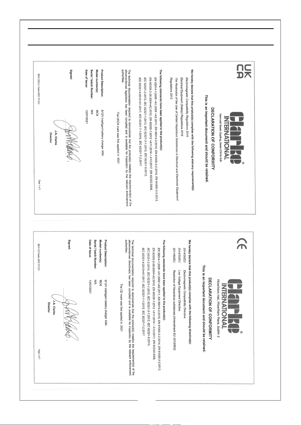
DECLARATION OF CONFORMITY
19
Parts & Service: 020 8988 7400 / E-mail: [email protected] or [email protected]
Page 20

 Loading...