

Page 1
WARNING: Do not use the machine without reading this manual
HOT WASHER
MODEL NO: HLS130
PART NO: 7320525
OPERATION & MAINTENANCE
INSTRUCTIONS
GC0314
Page 2
INTRODUCTION
Thank you for purchasing this CLARKE Hot Washer.
The machine has been designed to use hot or cold water to clean any
surfaces which can stand the force of the high pressure water jet and the
action of the detergents used.
The machine must only be used for the purpose for which it was designed.
Before attempting to use this product, please read this manual thoroughly and
follow the instructions carefully. In doing so you will ensure the safety of yourself
and that of others around you, and you can look forward to your purchase
giving you long and satisfactory service.
GUARANTEE
This product is guaranteed against faulty manufacture for a period of 12
months from the date of purchase. Please keep your receipt which will be
required as proof of purchase.
This guarantee is invalid if the product is found to have been abused or
tampered with in any way, or not used for the purpose for which it was
intended.
Faulty goods should be returned to their place of purchase, no product can
be returned to us without prior permission.
This guarantee does not effect your statutory rights.
LIST OF CONTENTS
The following items should be supplied in the carton. If any parts are missing or
damaged, please see your Clarke dealer where you purchased the machine.
1 x Hot Washer
1 x High Pressure Hose
1 x Spray Gun Assembly
1 x Lance Assembly
1 x Operating & Maintenance Manual
2
Parts & Service: 020 8988 7400 / E-mail: [email protected] or [email protected]
Page 3
GENERAL SAFETY RULES
WARNING: WATER AT HIGH PRESSURE CAN BE DANGEROUS AND CAN
CAUSE DAMAGE IF THE OPERATOR IS CARELESS. NEVER ALLOW ANYONE
TO OPERATE THIS MACHINE UNLESS THEY ARE FAMILIAR WITH THE SAFETY
PRECAUTIONS.
1. WARNING: High pressure water jets can be dangerous if subject to misuse.
They must not be directed at animals or people in order to clean clothes.
2. WARNING: Never allow children or untrained personnel to use this product.
3. NEVER operate the pressure washer with any of the covers removed.
4. NEVER attempt any electrical or mechanical repairs to this pressure washer.
Always refer to your Clarke dealer.
5. NEVER supply any liquid other than water to the water inlet.
6. WARNING: Never use the detergent facility to introduce flammable
liquids/solvents, e.g. paint thinners, petrol, oil due to risk of explosion.
7. ALWAYS release any residual pressure in the machine by turning off the
water supply and operating the trigger, before disconnecting the hose.
8. ALWAYS keep the pressure washer itself dry and clear of water spray.
9. WARNING: Never direct the spray jet at the pressure washer itself or any
other electrical equipment.
10. ALWAYS wear protective clothing, safety shoes and safety glasses. Loose
particles & other debris may be propelled at high speed by the water jet.
11. ALWAYS hold the spray gun firmly & expect the gun to ‘kick’ when starting.
12. WARNING: Only use chemical cleaning agents (detergents), that are
approved for pressure washers. CLARKE Traffic Film Remover or CLARKE
Wash and WAX (available from your dealer), are recommended.
13. WARNING: Always disconnect from the electrical power supply and
remove the plug from the socket before carrying out user maintenance.
14. ONLY u se or ig in al sp ar e p ar ts fr om the Clarke service department.
15. WARNING: High pressure hoses, fittings and couplings are important
for the safety of the machine. Use only hoses, fittings and
couplings recommended by the manufacturer.
16. NEVER use the pressure washer if a power cable or important
parts of the pressure washer are damaged.
17. Use only clean Diesel Oil. NEVER use gasoline, kerosene, paint thinners,
alcohol or other highly flammable fuels.
18.WARNING: If an extension cable is used, the cable/plug must be fully
watertight. Inadequate extension cables can be dangerous.
3
Parts & Service: 020 8988 7400 / E-mail: [email protected] or [email protected]
Page 4
SAFETY SYMBOLS
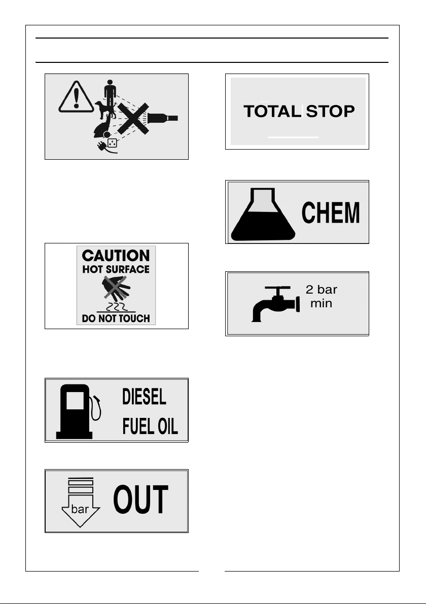
WAR NI NG : Do not discharge the water
spray at persons or animals. Keep clear
of nozzle.
WAR NI NG : Never direct spray toward
any electrical device or electrical
outlet.
WAR NI NG : Risk of hot surfaces. Avoid
hot exhaust components. Don't allow
hoses to contact the exhaust exit
during or after use.
Fuel Tank
Total Stop System
Detergent Tank
Water Input
High Pressure Water Outlet
4
Parts & Service: 020 8988 7400 / E-mail: [email protected] or [email protected]
Page 5
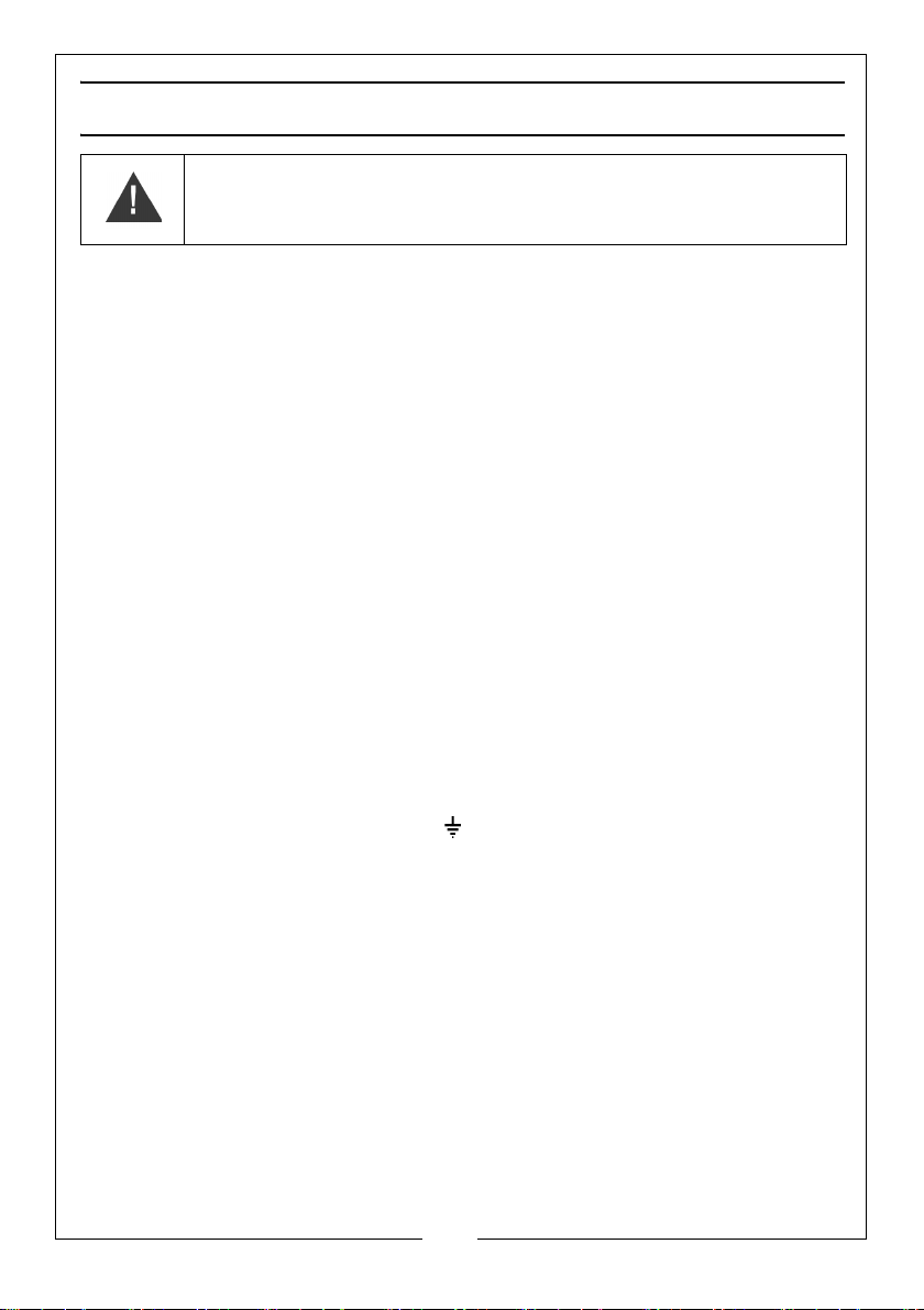
ELECTRICAL CONNECTIONS
WARNING! Read these electrical safety instructions thoroughly
before connecting the product to the mains supply.
Before switching the product on, make sure that the voltage of your electricity
supply is the same as that indicated on the rating plate. This product is
designed to operate on 230VAC 1ph 50Hz. Connecting it to any other power
source may cause damage.
Connect the mains lead to a suitably fused 230V, 1 phase electrical supply via
a 16 Amp industrial 3-pin connector (to BSEN 60309-1/2).
IMPORTANT: A domestic 13Amp plug MUST NOT be fitted to this appliance.
The electrical supply connection shall be made by a suitably qualified
electrician and comply with IEC 60364-1.
As the colours of the wires in the power cable of this product may not
correspond with the markings on the terminals of your plug, proceed as
follows.
If the colours of the wires in the power cable of this product do not correspond
with the markings on the terminals of your plug, proceed as follows.
• The wire which is coloured Blue must be connected to the terminal
which is marked N.
• The wire which is coloured Brown must be connected to the terminal
which is marked L.
• The wire which is coloured Yellow and Green must be connected to the
terminal which is marked E or or coloured Green.
We strongly recommend that this machine is connected to the mains supply
via a Residual Current Device (RCD).
FUSE RATING
The fuse rating for this pressure washer is 16Amps.
EXTENSION CABLES
If an extension cable is used, always ensure it is fully unwound. When used
outdoors, ensure that the extension cable is specifically designed for outdoor
use. Ensure that the cable is rated for the voltage and amperage of the
machine.
If in any doubt, consult a qualified electrician. DO NOT attempt any repairs
yourself.
5
Parts & Service: 020 8988 7400 / E-mail: [email protected] or [email protected]
Page 6
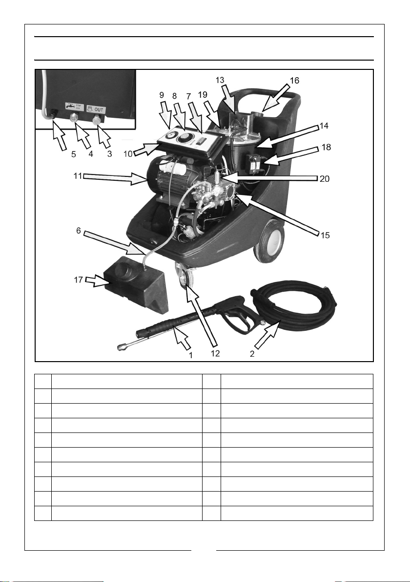
PARTS IDENTIFICATION
1 Spray Gun and Lance 11 Electric Motor
2 High Pressure Hose 12 Braked Castor
3 Water Outlet 13 Exhaust
4 Water Inlet 14 Boiler
5 Power Cable 15 High Pressure Pump
6 Detergent Pickup Hose 16 Fuel Tank Filler Cap
7 On/OFF Switch 17 Detergent Tank
8 Temperature Regulator 18 Transformer
9 Pressure Gauge 19 Burner Head
10 Control Panel 20 By-pass Valve
6
Parts & Service: 020 8988 7400 / E-mail: [email protected] or [email protected]
Page 7
BEFORE USE
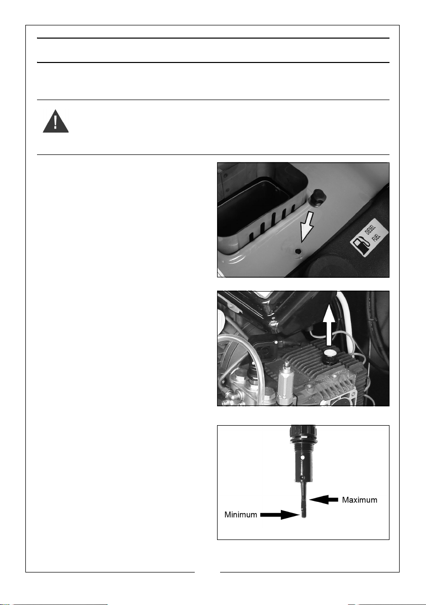
CHECKING THE OIL
WARNING: TO CARRY OUT THIS CHECK, PLACE THE PRESSURE WASHER ON
LEVEL GROUND WHILE SWITCHED OFF.
WARNING: TAKE CARE NOT TO TOUCH ANY HOT PARTS WHEN CHECKING
THE OIL LEVEL.
1. Remove the cover from the
pressure washer by removing the
securing thumbscrew from the
front and then the rear of the
cover then lifting it off.
2. Turn the oil filler cap anticlockwise
to remove it from the pump and
wipe the integral dipstick with a
clean cloth.
3. Insert the oil filler cap fully back
into place and then remove it
again.
4. If the oil is near the low mark on
the dipstick, add oil to the oil
reservoir.
• Do not overfill the oil reservoir.
• We recommend the use of
SAE30 oil.
• Do not mix grades of oil as this may effect the machine’s performance.
7
Parts & Service: 020 8988 7400 / E-mail: [email protected] or [email protected]
Page 8
5. Replace the oil filler cap.
6. Replace the cover and tighten the securing screws
CAUTION: RUNNING THE PUMP WITH INSUFFICIENT OIL WILL CAUSE
DAMAGE
FILLING WITH FUEL
• Refuel in a well-ventilated area.
• Do not leave fuel within the
reach of children.
• Refuel carefully to avoid
spillages.
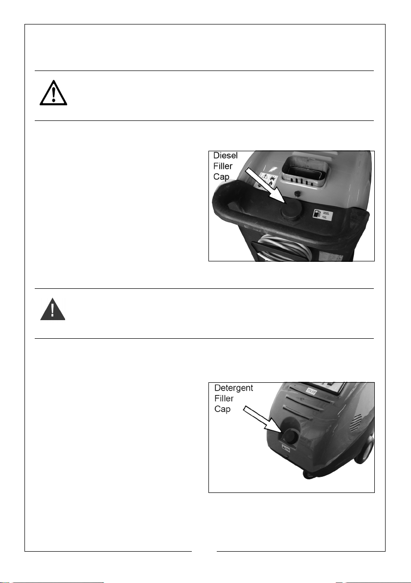
1. Remove the diesel filler cap and
fill the tank with diesel fuel.
• Maximum 22 litres.
2. Replace the diesel filler cap
securely.
WARNING: INCORRECT FUELS MUST NOT BE USED AS THEY MAY PROVE
HAZARDOUS.
FILLING WITH DETERGENT
If you intend to use the detergent injection facility:
1. Unscrew the Detergent Filler Cap
located at the front of the
machine and fill with detergent.
• Only use detergents
recommended for use with
pressure washers, such as
CLARKE Traffic Film Remover
which is a powerful ‘low
foaming’ agent for car
cleaning, patio cleaning etc.,
or CLARKE Wash & Wax, both
available from your CLARKE dealer. The use of unsuitable cleaning
agents may adversely affect the safety of the machine. Do not exceed
the correct operating temperature.
8
Parts & Service: 020 8988 7400 / E-mail: [email protected] or [email protected]
Page 9
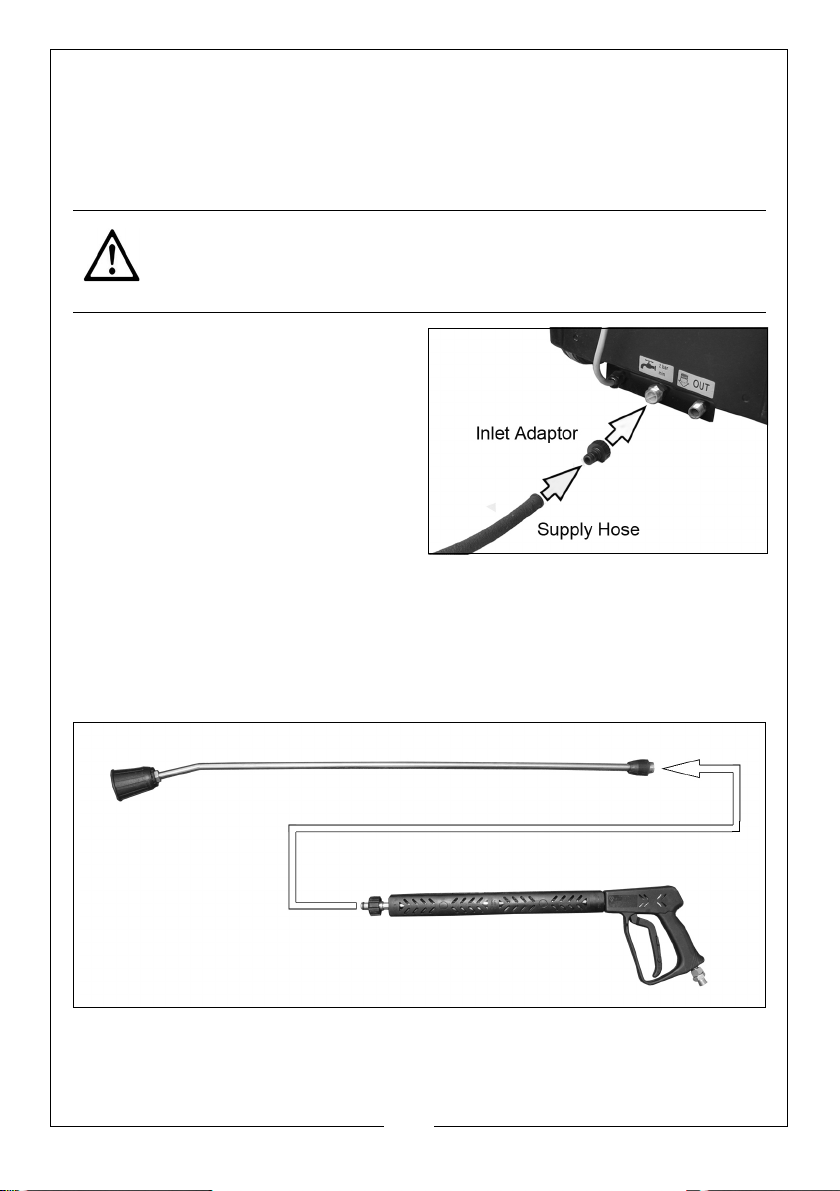
CONNECTING THE MAINS WATER SUPPLY
The pressure washer must never be connected to the drinking water supply
without using a system separator (also known as a backflow preventer)
available from most hardware stores.
Always follow the regulations of your local water supplier.
CAUTION: WATER THAT HAS FLOWED THROUGH A SYSTEM SEPARATOR IS
CONSIDERED NON-DRINKABLE.
1. Connect the water supply hose to
the inlet adaptor supplied with the
machine. A standard proprietary
hose is suitable.
2. Screw the inlet adaptor to the
water inlet as shown.
• It is recommended to use a
reinforced hose having an
inner diameter of at least 10
mm.
• The water supply must be able to deliver at least 15 l/min and have a
max inlet temperature of 65°C.
ASSEMBLING THE LANCE
1. Connect the spray lance to the gun assembly and tighten securely by
turning the locking ring.
9
Parts & Service: 020 8988 7400 / E-mail: [email protected] or [email protected]
Page 10
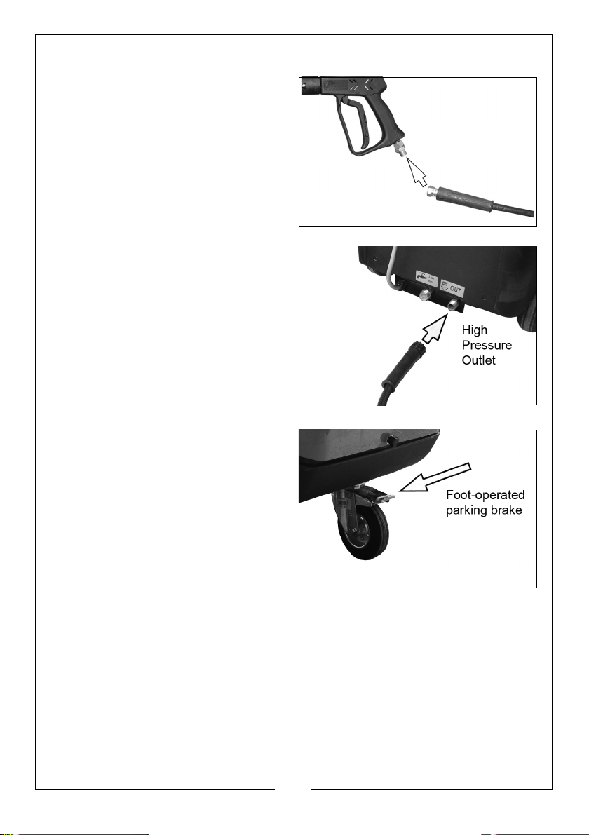
CONNECTING THE HIGH PRESSURE HOSE
1. Screw the high pressure hose onto
the gun assembly.
2. Use a spanner to tighten the
connector.
3. Screw the other end of the hose
on to the pressure washer outlet.
• Tighten the connector hand
tight only;- do not use a
spanner.
NOTE: Make sure the connections
are secure.
PARKING BRAKE
Before you operate your pressure
washer you should make sure that
the parking brake is engaged.
To do this press the brake flap shown
in the picture against the wheel to
engage the parking brake.
Flip the flap upwards to release the
brake and allow you to move the
pressure washer.
10
Parts & Service: 020 8988 7400 / E-mail: [email protected] or [email protected]
Page 11
OPERATION
1. The pressure washer should always be located on a firm level surface
where it is not exposed to extreme weather conditions such as strong wind,
freezing or rain.
2. It is recommended that where possible a partition be erected between the
wash area and the pressure washer to prevent accidental spraying of the
pressure washer. Moisture entering the machine may cause damage.
WARNING: DO NOT OPERATE THE PRESSURE WASHER INDOORS, OR IN
ENCLOSED AREAS WITHOUT ADEQUATE VENTILATION, OR IN AREAS
WHERE FLAMMABLE VAPOURS (PETROL, SOLVENTS ETC.) MAY BE PRESENT.
WARNING: IF THE PRESSURE WASHER IS TO BE USED IN AN ENCLOSED
AREA THE BURNER EXHAUST MUST BE VENTED TO THE OUTSIDE
ATMOSPHERE. THE USE OF A DRAFT REGULATOR IS RECOMMENDED. ALL
VENTING MUST BE IN ACCORDANCE WITH APPLICABLE LAWS AND LOCAL
ORDINANCES FOR SUCH INSTALLATIONS.
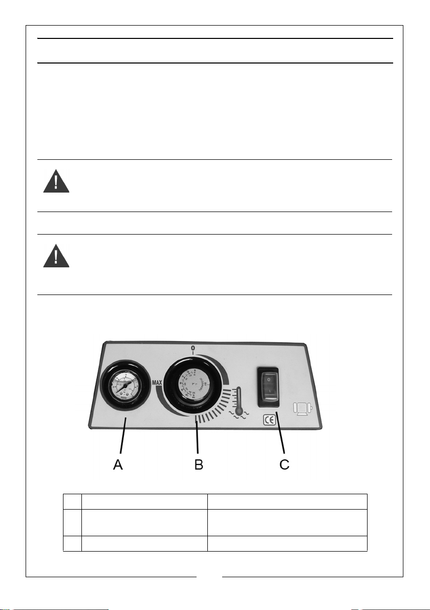
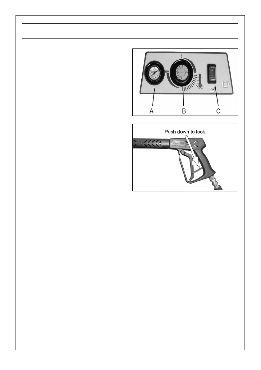
CONTROL PANEL
l
A Pressure Gauge Displays hot water pressure
B Temperature regulator
(from 30°C to 150 °C.)
C ON/OFF Switch Turns machine On/Off.
Parts & Service: 020 8988 7400 / E-mail: [email protected] or [email protected]
Selects water temperature.
11
Page 12
GETTING STARTED
1. Ensure that the water supply is correctly connected and turned on.
WARNING: FAILURE TO TURN ON THE WATER FULLY COULD CAUSE
DAMAGE TO THE PRESSURE WASHER.
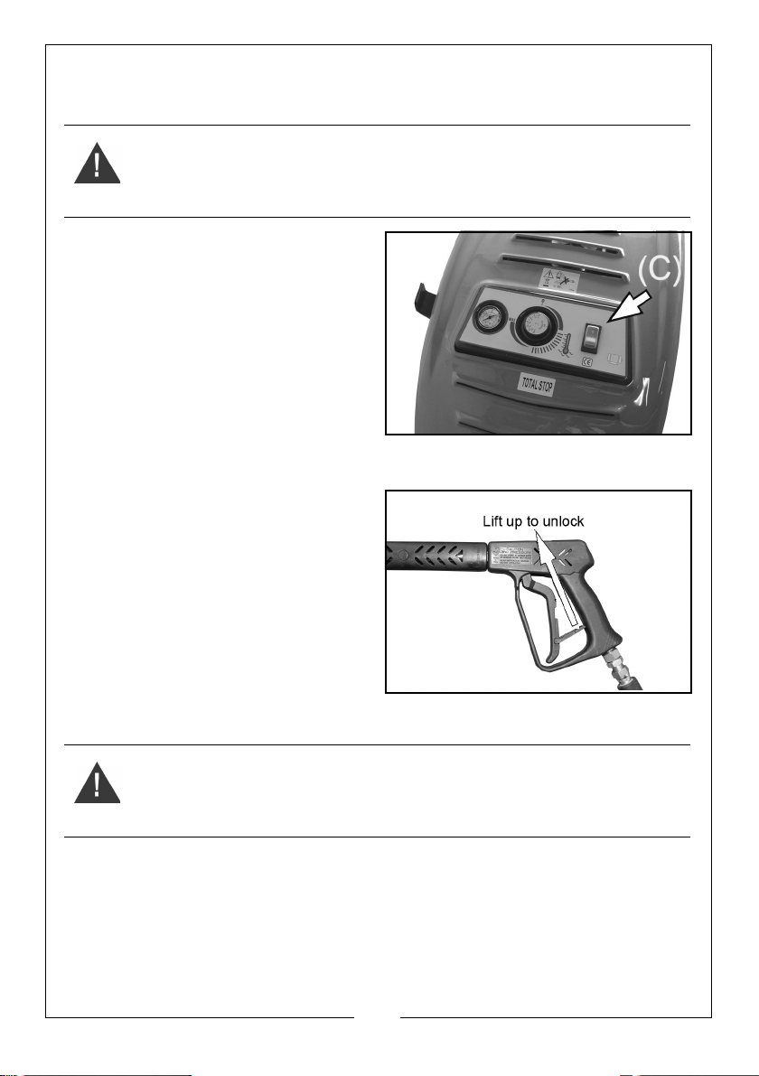
2. Set the start switch (C) to ‘I’.
3. Release the trigger lock.
4. When using the machine for the
first time, let it run for a few
moments without the nozzle so
that any air bubbles or other
impurities are discharged.
5. Then re-fit the nozzle. pull the
trigger for a few seconds to
discharge any air contained in
the hose.
NOTE: When the trigger is pulled the
pressure of water will cause
the lance/gun assembly to
kick back suddenly.
6. The washer incorporates a total
stop system. When the trigger is
released the motor will stop. This
system is designed to protect the
motor and is also an important
safety feature.
USING THE WASHER AT DIFFERENT TEMPERATURES
WARNING: THE BURNER EXHAUST MUST BE VENTED TO THE OUTSIDE
ATMOSPHERE. ALL VENTING MUST BE IN ACCORDANCE WITH APPLICABLE
LAWS AND LOCAL ORDINANCES FOR SUCH INSTALLATIONS.
1. Set the Temperature Selector (B) to the required temperature.
2. Set the start switch (C) to ‘I’.
3. Ensuring that you have a firm footing and that you are also holding the gun
and spray lance firmly, pull the trigger on the gun to start water flow.
• The lance and gun will kick back when the trigger is first pulled.
12
Parts & Service: 020 8988 7400 / E-mail: [email protected] or [email protected]
Page 13
• If heating of the water is required, the burner will light up to produce hot
water at the required temperature.
• The pressure washer is now ready for use.
• The machine should always be attended during hot wash operation.
4. Having used the pressure washer with hot water, set the temperature
selector to the minimum temperature and allow it to run with cold water for
a few moments before switching off.
5. At the end of the working session, switch off at the start switch (C) and by
pulling the trigger, to allow any residual pressure to be released.
USING DETERGENT
WARNING: IF OPERATING THE MACHINE WITH DETERGENT INCLUDING
CLARKE CLEANING PRODUCTS, TAKE CARE NOT TO SET THE MACHINE TO
OPERATING TEMPERATURES OF GREATER THAN 100
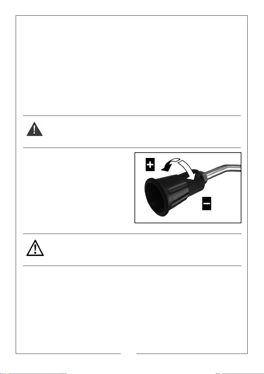
The detergent is applied by twisting
the cap on the lance as shown to
produce a wider spray pattern with
lower pressure, and then pulling the
trigger on the gun.
O
C.
When the nozzle is adjusted to a high
pressure and a narrow spray pattern,
the detergent flow is halted.
CAUTION: IF YOUR EYES COME INTO CONTACT WITH ANY CLEANING
FLUIDS, RINSE THEM IMMEDIATELY WITH PLENTY OF FRESH CLEAN WATER
AND SEEK MEDICAL ADVICE IF REQUIRED.
13
Parts & Service: 020 8988 7400 / E-mail: [email protected] or [email protected]
Page 14
AFTER USE
1. Set the start switch (C) to ‘O’.
2. Turn the water supply off at the
tap.
• NEVER turn the water off with
the pressure washer running.
3. Release the pressure in the pump
and hose by squeezing the trigger
for a few seconds until no more
water comes out of the nozzle.
4. Move the trigger lock to the
locked position.
5. Store the pressure washer in a dry
safe place to prevent
unauthorised persons from using it.
14
Parts & Service: 020 8988 7400 / E-mail: [email protected] or [email protected]
Page 15
MAINTENANCE
• All repairs and maintenance operations must be carried out by
technically qualified personnel.
• All maintenance operations must be carried out with the machine on a
level floor while disconnected from the power and water supplies.
• Correct use and maintenance is necessary to guarantee the pressure
washer's reliability and best performance.
• The pressure washer requires regular checks to be carried out at the
following intervals. Please only use the correct spare parts as supplied by
your Clarke dealer.
DAILY (BEFORE EACH USE)
CHECK THE OIL LEVEL OF THE PUMP
1. See “Checking the oil” on page 7.
2. Check that the power cable is not damaged.
EVERY 2 WEEKS OR AFTER 50 HOURS WORKING
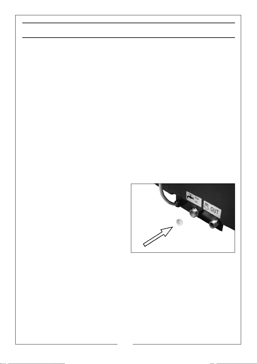
CLEAN THE WATER FILTER
1. Use a pair of square nosed pliers,
pull out the inlet water filter
located in the water inlet and
clean out any foreign matter.
15
Parts & Service: 020 8988 7400 / E-mail: [email protected] or [email protected]
Page 16
EVERY 3 MONTHS OR AFTER 300 HOURS OF WORK
CLEANING/REPLACING THE FUEL FILTER
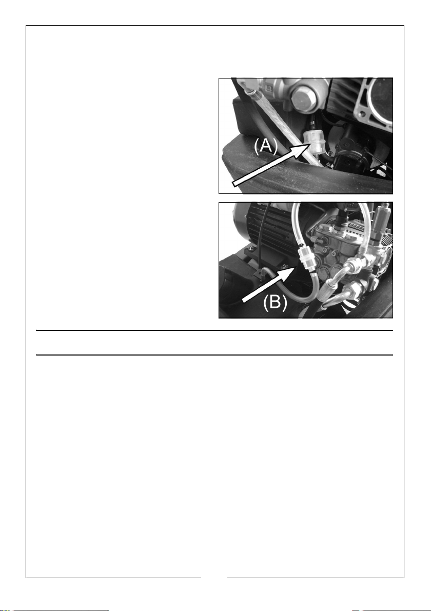
1. Remove the cover from the
pressure washer.
2. Remove & replace the fuel filter
(A).
3. Clean or replace the detergent
filter (B).
If dirty, either clean with a jet of
compressed air or replace it with a
new filter.
SERVICING
These tasks must be carried out by skilled service personnel.
EVERY MONTH OR AFTER 100 HOURS OF OPERATION
CLEANING THE COMBUSTION HEAD & CHECKING THE ELECTRODES
It is recommended that the burner and electrodes be serviced yearly, or
as needed depending upon the pressure washers' usage.
Please contact the CLARKE International Service Dept.
LIMESCALE
Periodically the heating coil should be checked for limescale buildup,
dependant upon the hardness of the local water supply.
Please contact the CLARKE International Service Dept.
SOOT BUILD UP
Poor grades of fuel oil or inadequate combustion will cause heavy build
up of soot on the heating coil. This deposit will insulate the coil and
16
Parts & Service: 020 8988 7400 / E-mail: [email protected] or [email protected]
Page 17
reduce its efficiency. It will also restrict air flow through the coil, further
aggravating the soot build up.
Contact your CLARKE dealer or CLARKE International Service Dept on:
020 8988 7400 if de-sooting is required.
DE-COMMISSIONING PRODUCT
Should the product become completely unserviceable and require disposal,
draw off the oil into an approved container and dispose of the product and
the oil according to local regulations.
Recycle unwanted materials instead of disposing of them as
waste. All tools, accessories and packaging should be sorted,
taken to a recycling centre and disposed of in a manner which is
compatible with the environment.
CONSUMABLES ETC
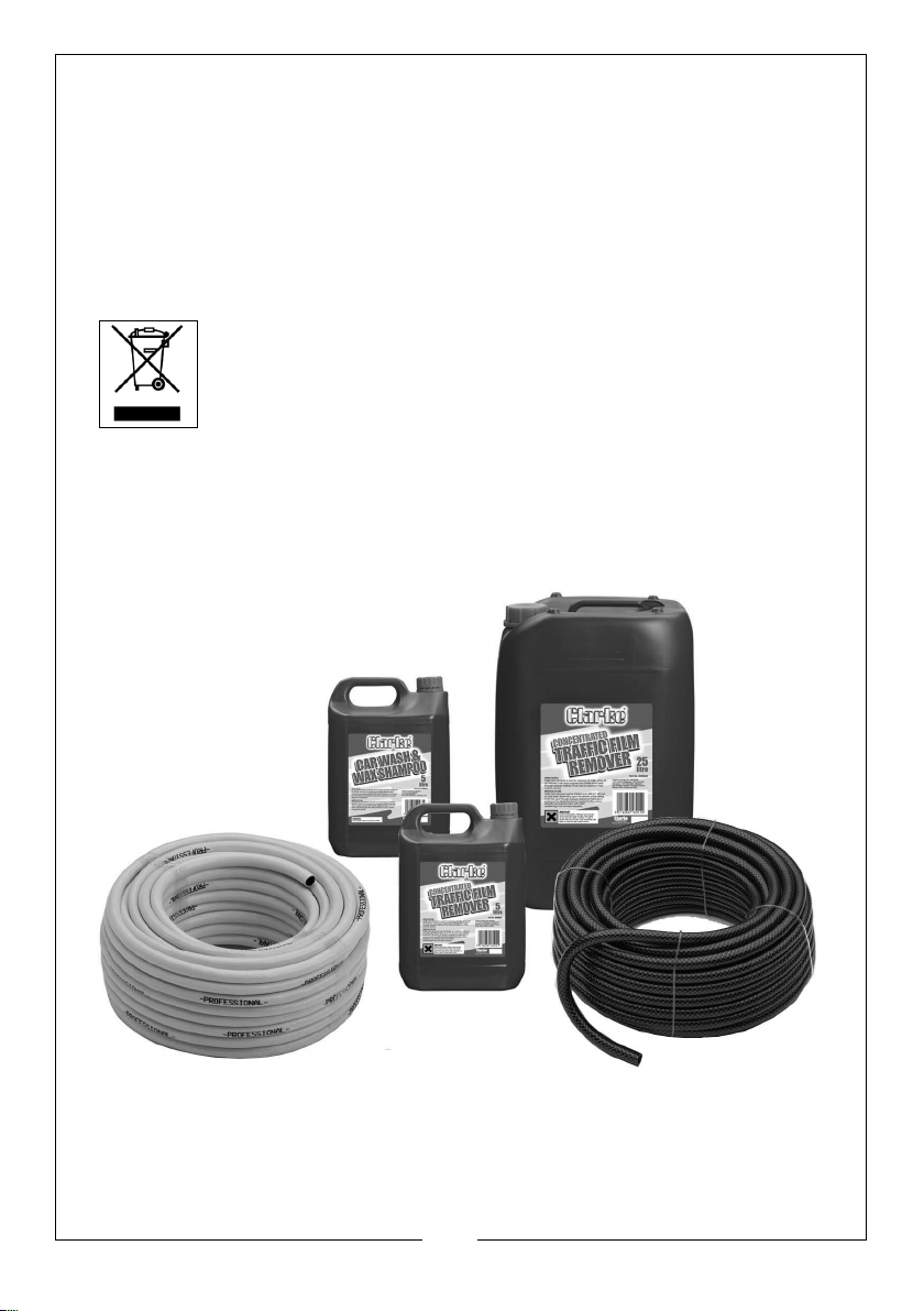
A range of suitable hoses, shampoo and traffic film remover are available
from your Clarke dealer.
17
Parts & Service: 020 8988 7400 / E-mail: [email protected] or [email protected]
Page 18

TROUBLESHOOTING
PROBLEM POSSIBLE CAUSE SOLUTION
No water delivery. Water filter blocked. See “Clean the water filter”
on page 15.
Pump valves jammed. Contact Clarke Service
Department.
Clogged lance nozzle. Clean the nozzle.
Low or irregular
pressure
The burner does
not turn on.
Insufficient water supply. Check connections.
Pump taking in air. Check connections.
Detergent valve sucking in
air.
Water filter dirty. Clean or replace.
Worn out gaskets or valve
components.
Exceeding the inlet water
temperature.
Damaged or warn out
nozzle components.
Coil is covered in limescale. Contact Clarke Service
Dirty burner nozzle. Contact Clarke Service
Faulty thermostat. Contact Clarke Service
Broken/blocked actuated
valve.
Dirty fuel filter. Clean or replace as shown on
Insufficient spark at the
electrodes.
Worn out pump mechanism. Contact Clarke Service
Low Voltage. Make sure the pressure
Check connections and that
detergent supply is toppedup
Contact Clarke Service
Department for replacement.
Make sure the water supply is
below 65 degrees.
Contact Clarke Service
Department for replacement
Department for advice on
de-scaling.
Department.
Department.
Contact Clarke Service
Department.
page16.
Contact Clarke Service
Department.
Department.
washer is connected to a
suitable power supply.
18
Parts & Service: 020 8988 7400 / E-mail: [email protected] or [email protected]
Page 19
Machine is noisy. Air intake worn out / dirty/
blocked valves. Excess
water temperature.
Water in the oil. Worn out piston rings/failed
gaskets.
Oil leaking from
Worn out o-rings or gaskets. Contact Clarke Service
the head.
Motor suddenly
stops.
Thermal protection has
activated due to
overheating.
Check air inlet. Contact
Clarke Service Department.
Reduce water temperature.
Contact Clarke Service
Department.
Department.
Switch off the machine and
wait until the unit has cooled
down sufficiently.
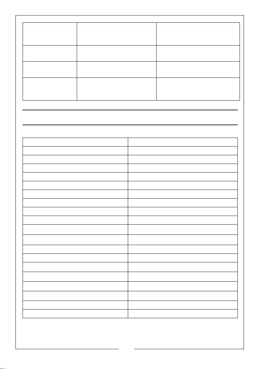
PRODUCT SPECIFICATIONS
Model Number HLS130
Part Number 7320525
Voltage 230 V / 50 Hz / 1 Phase
Motor Input Power 3.1 kw
Motor Input Current 14.3 A
Duty Cycle S1 (continuous)
Max Inlet Water Pressure 2.5 Bar
Working pressure 125 Bar / 1813 PSI
Maximum output pressure 130 Bar / 1885 PSI
Maximum output flow rate 600 Litres / hour
Maximum output temperature
Maximum input temperature
Fuel tank capacity 22 Litres
Detergent tank capacity 4 Litres
Sound power level (L
) 93 dB
WA
Guaranteed sound power level (LWA) 94 dB
Vibration
Uncertainty Factor
Dimensions (L x W x H) 1000 x 570 x 820 mm
Weight 97.5 kg
o
150
C
65oC
1.23 m/s
1.5 m/s
2
2
19
Parts & Service: 020 8988 7400 / E-mail: [email protected] or [email protected]
Page 20
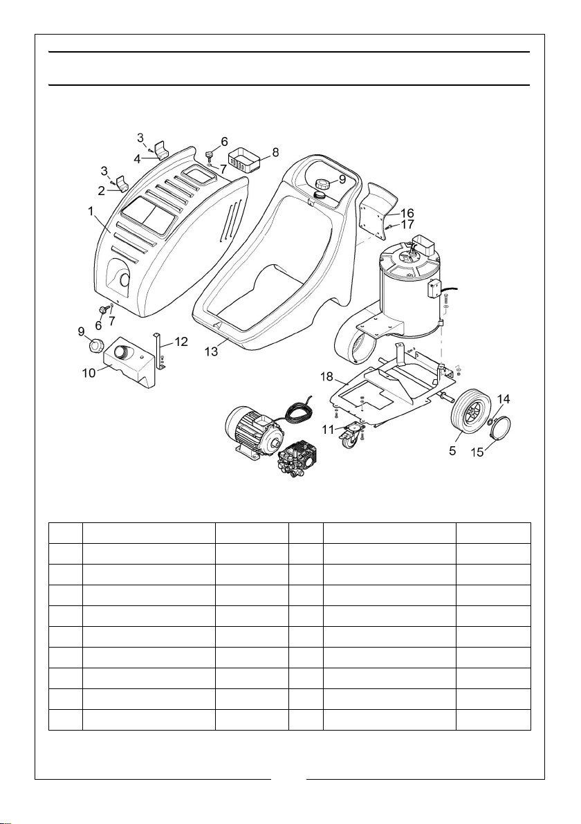
PARTS LIST - FRAME & BODY
POS DESCRIPTION CODE POS DESCRIPTION CODE
1 Machine Cover AR3160731 10 Detergent Tank AR3163900
2 Front Hose Carrier AR3160100 11 Braked Caster AR3164410
3 Screw AR2100300 12 Bracket AR3163910
4 Rear Hose Carrier AR3160110 13 Fuel Tank AR3161550
5 Wheel AR3164380 14 Wheel Retaining Clip AR3162010
6 Securing Knob AR3163890 15 Hub Cover AR3161940
7 Washer AR3163290 16 Power Cable Carrier AR3160090
8 Exhaust Guard AR3163880 17 Screw AR2360360
9 Detergent Filler Cap AR3161920 18 Chassis Frame AR3160710
20
Parts & Service: 020 8988 7400 / E-mail: [email protected] or [email protected]
Page 21
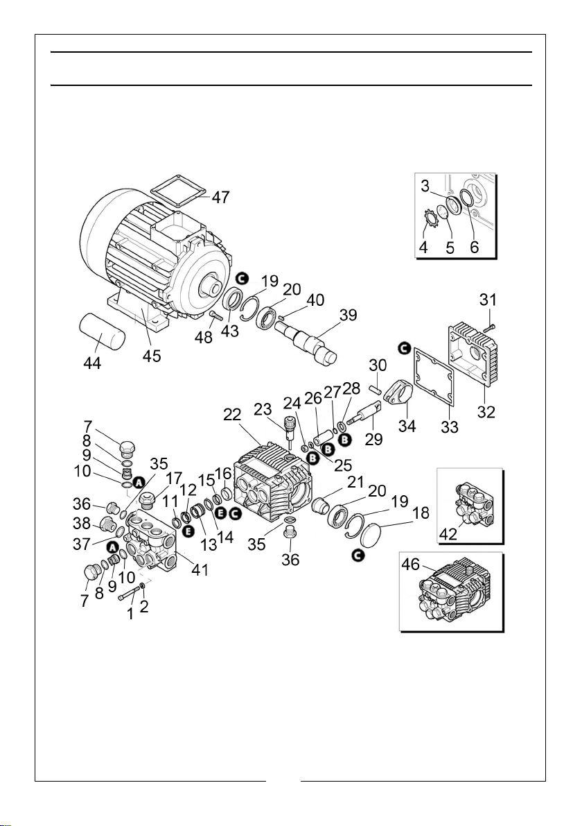
PARTS LIST - WATER PUMP ASSEMBLY
21
Parts & Service: 020 8988 7400 / E-mail: [email protected] or [email protected]
Page 22
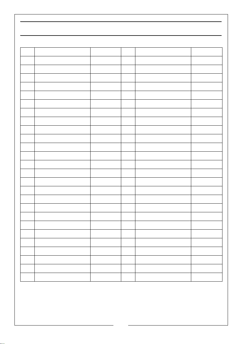
PARTS LIST - WATER PUMP ASSEMBLY
POS DESCRIPTION CODE POS DESCRIPTION CODE
1 Bolt AR680570 27 O-ring AR480480
2 Washer AR1381550 28 Plate AR1260091
3 Oil Level Glass AR1260250 29 Piston AR1260070
4 Securing Ring AR1260430 30 Pin AR1260080
5 Plate AR1780690 31 Screw AR1260750
6 O-Ring AR1140450 32 Cover AR1329010
7 Plug AR1260162 33 Oil Gasket Seal AR1329010
8 O-ring AR960160 34 Connecting Rod AR1320140
9 Complete Valve AR1269050 35 O-ring AR740290
10 O-ring AR880830 36 Plug AR1980740
11 Ring AR1320340 37 O-ring AR180101
12 Water Seal AR178020 38 Plug AR1980740
13 Piston Guide AR1320351 39 Pump Cam Shaft AR1322780
14 O-ring AR1260420 40 Key AR1380520
15 Water Seal AR1260450 41 Pump Head AR1230020
16 Oil Seal AR1260460 42 Head Assembly AR1269299
17 Plug AR1260164 43 Sealing Ring AR1260750
18 Oil Seal AR1266740 44 Capacitor AR51230
19 Circlip AR1260790 45 Pump Motor AR44272
20 Bearing AR1320370 46 Pump Assembly AR20566
21 Bushing AR1320330 47 Gasket AR50068
22 Pump Body AR1320010 48 Screw AR1200430
23 Plug AR880130 A Valve Overhaul Kit AR1864
24 Nut AR1260110 B Piston Overhaul Kit AR2629
25 Washer AR1260100 C Oil Seal Kit AR1872
26 Piston AR1260210 E Water Seal Kit AR42479
22
Parts & Service: 020 8988 7400 / E-mail: [email protected] or [email protected]
Page 23
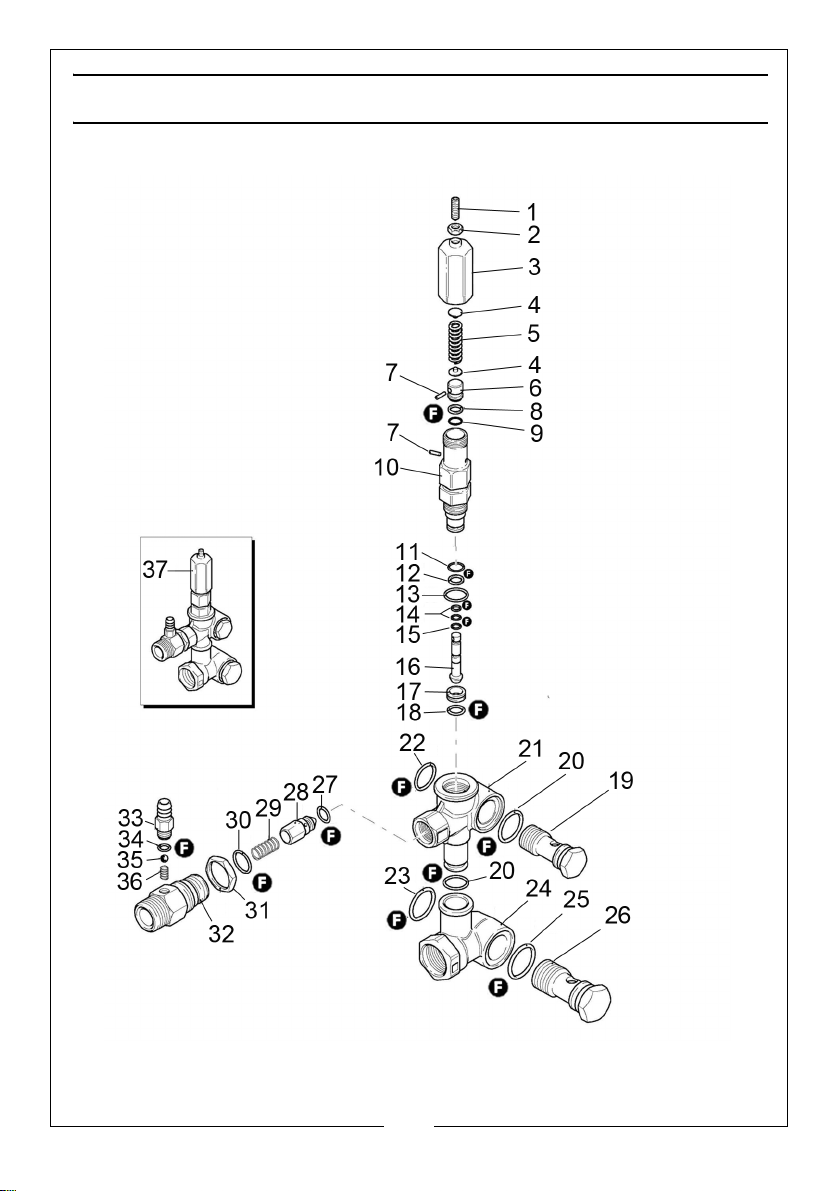
PARTS DIAGRAM - VALVE ASSEMBLY
23
Parts & Service: 020 8988 7400 / E-mail: [email protected] or [email protected]
Page 24
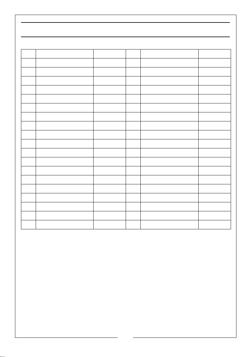
PARTS DIAGRAM - VALVE ASSEMBLY
POS DESCRIPTION CODE POS DESCRIPTION CODE
1 Screw AR1540560 20 O-ring AR390080
2 Nut AR1980470 21 Valve Body AR1540510
3 Insert AR1980390 22 O-ring AR1140450
4 Wobble Plate AR1980220 23 O-ring AR1540630
5 Spring AR1271070 24 Suction Fitting AR1540280
6 Piston AR1080041 25 O-ring AR880270
7 Pin AR1080070 26 Connector AR2260420
8 O-Ring AR1080401 27 O-ring AR1460430
9 O-ring AR1080250 28 Shutter Fitting AR1540170
10 Piston Guide AR1980210 29 Spring AR1080090
11 O-ring AR740290 30 O-ring AR394280
12 O-ring AR800560 31 Nut AR1540300
13 O-ring AR880830 32 Fitting AR1540170
14 Ring AR1271170 33 Hose Tail Fitting AR1560490
15 O-ring AR1080190 34 O-ring AR480480
16 Piston AR1271160 35 Ball AR1250280
17 Valve Seat AR1980200 36 Spring AR1560520
18 O-ring AR1470210 37 Valve (Complete) AR23030
19 Connector AR1540270 F Gasket/O-ring Set AR2812
24
Parts & Service: 020 8988 7400 / E-mail: [email protected] or [email protected]
Page 25
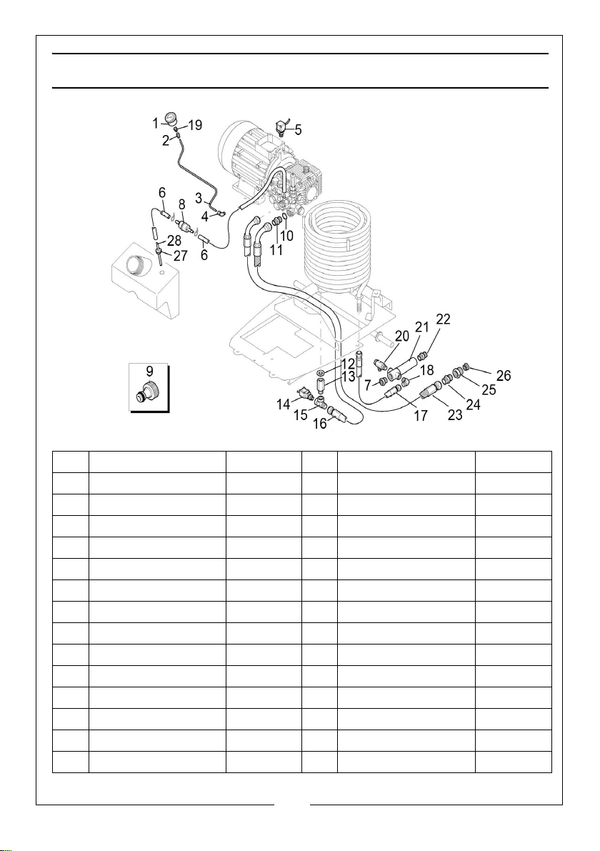
PARTS DIAGRAM - CONNECTING HOSES
POS DESCRIPTION CODE POS DESCRIPTION CODE
1 Pressure Gauge AR3161040 15 Fitting AR3160510
2 Fitting AR3164070 16 Pump Outlet Pipe AR3164400
3 Pipe AR3163500 17 Delivery Pipe AR3161310
4 Fitting AR3161110 18 Elbow Fitting AR3161190
5 Pressure Switch AR3162890 19 Fitting AR3161260
6 Detergent Hose AR3163850 20 Valve AR3160540
7 End Fitting AR3161210 21 Fitting AR3161170
8 Detergent Filter AR3163560 22 Outlet Connector AR3161150
9 Hose Connector AR1461470 23 Mains Inlet Pipe AR3161290
10 O-ring AR480440 24 Fitting AR3161180
11 Hose Fitting AR1540050 25 Inlet Hose Fitting AR3160480
12 Washer AR3162040 26 Water Inlet Filter AR50713
13 Fitting AR3160430 27 Gland AR3161050
14 Pressure Switch AR3161080 28 Pickup Pipe AR3163840
25
Parts & Service: 020 8988 7400 / E-mail: [email protected] or [email protected]
Page 26
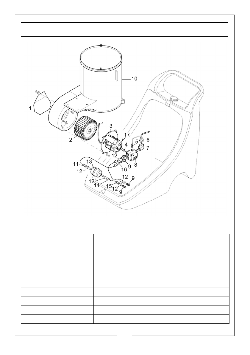
PARTS DIAGRAM - FAN & FUEL PUMP
POS DESCRIPTION CODE POS DESCRIPTION CODE
1 Cover Plate AR3161900 10 Boiler Housing AR3161460
2 Fan AR3161810 11 Connecting Pipe AR3161620
3 Motor Assembly AR3161530 12 Tubing Clamp AR3162060
4 Coupling AR3160300 13 Fuel Filter AR3161520
5 Fitting AR3160330 14 Fuel Pickup Pipe AR3161610
6 Plug-in Cable AR3161440 15 Fuel Return Pipe AR3161580
7 Solenoid AR3160320 16 Pipe Clamp AR3163920
8 Fuel Pump AR3162910 17 Screw AR3163540
9 Hosetail Fitting AR3160340
26
Parts & Service: 020 8988 7400 / E-mail: [email protected] or [email protected]
Page 27
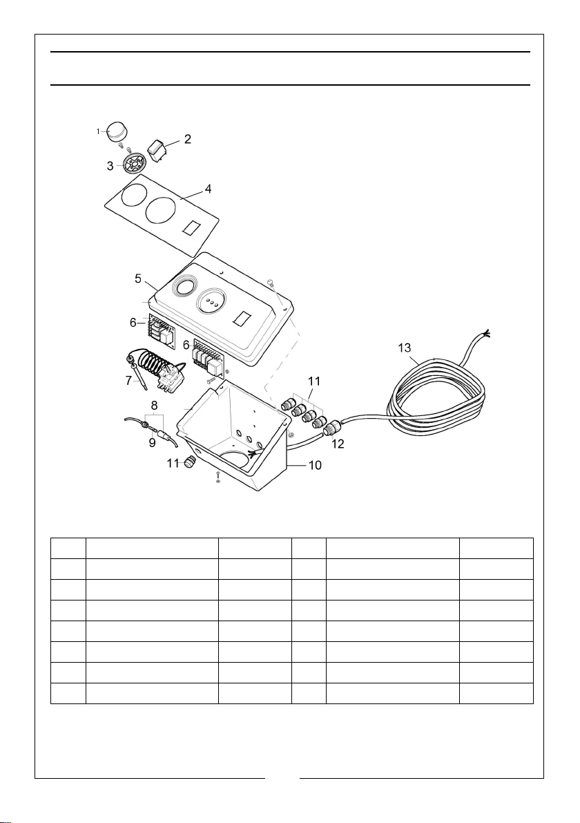
PARTS DIAGRAM - CONTROLS BOX
POS DESCRIPTION CODE POS DESCRIPTION CODE
1 Temp Control Knob AR3161960 7 Thermostat AR50720
2 On/Off Switch AR3160850 8 Fuse Holder AR3163720
3 Control Housing AR3161990 9 Fuse AR3160920
4 Display Panel AR3162080 10 Control Box AR3160930
5 Cover Plate AR3160940 11 Cable Gland AR3160860
6 Board - ALB 012 AR3160900 12 Cable Gland AR3160870
6 Board - TSP 16 AR3163660 13 Cable AR3160800
27
Parts & Service: 020 8988 7400 / E-mail: [email protected] or [email protected]
Page 28
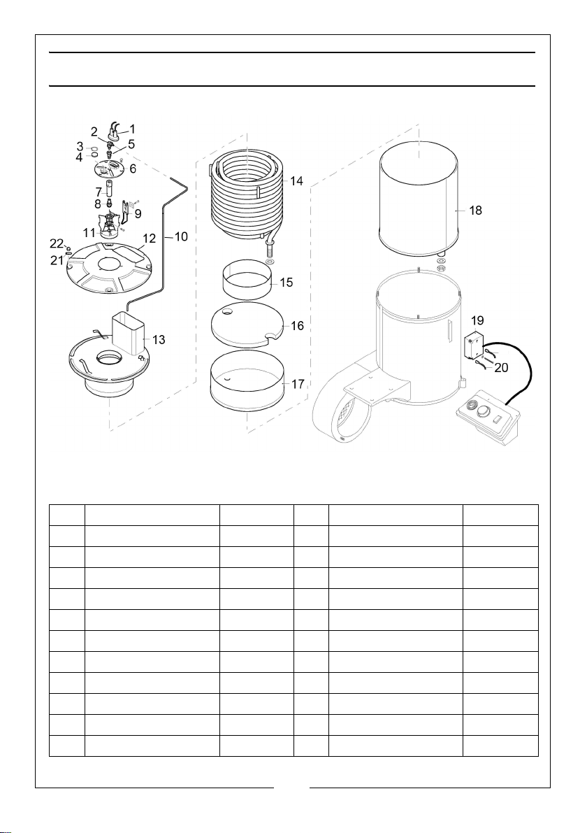
PARTS DIAGRAM - BOILER
POS DESCRIPTION CODE POS DESCRIPTION CODE
1 Cable Protector AR3162370 12 Top Cover AR3161790
2 Fitting AR3161100 13 Cover with Flue AR3161780
3 O-Ring AR3162030 14 Coil AR3161750
4 Glass AR3161860 15 Support Ring AR3161430
5 Fitting AR3161230 16 Bottom Plate AR3161830
6 Plate AR3161840 17 Cover AR3161770
7 Nozzle Holder AR3161870 18 Boiler Shell AR3161450
8 Nozzle AR3162820 19 Danfoss Transformer AR50717
9 Electrode AR3161890 20 Transformer Cable AR3160830
10 Rigid Pipe AR3161880 21 Washer AR3163940
11 Burner Support AR3161560 22 Nut AR3163960
28
Parts & Service: 020 8988 7400 / E-mail: [email protected] or [email protected]
Page 29
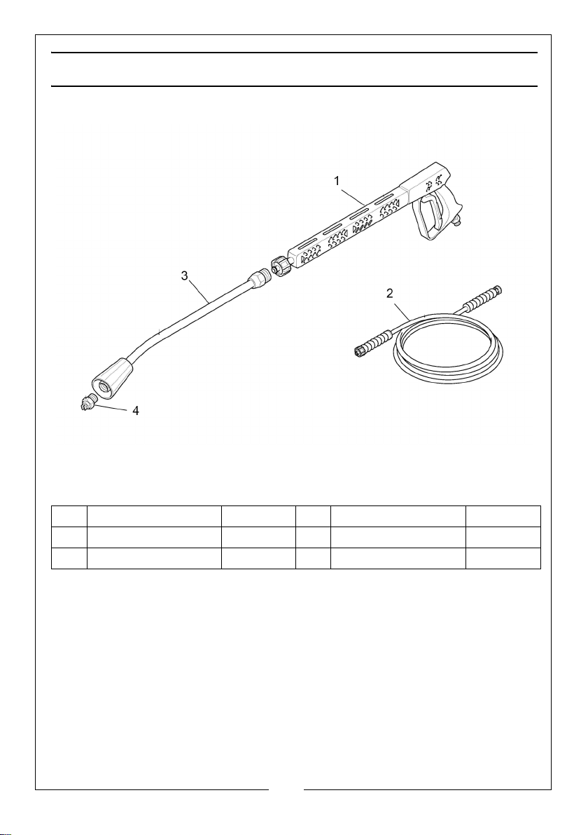
PARTS DIAGRAM - SPRAY GUN & LANCE
POS DESCRIPTION CODE POS DESCRIPTION CODE
1 Gun AR41089 3 Lance AR40826
2 High Pressure Hose AR3160160 4 Nozzle AR3082
29
Parts & Service: 020 8988 7400 / E-mail: [email protected] or [email protected]
Page 30
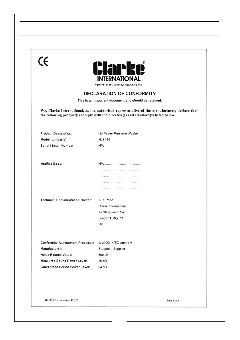
DECLARATION OF CONFORMITY
30
Parts & Service: 020 8988 7400 / E-mail: [email protected] or [email protected]
Page 31
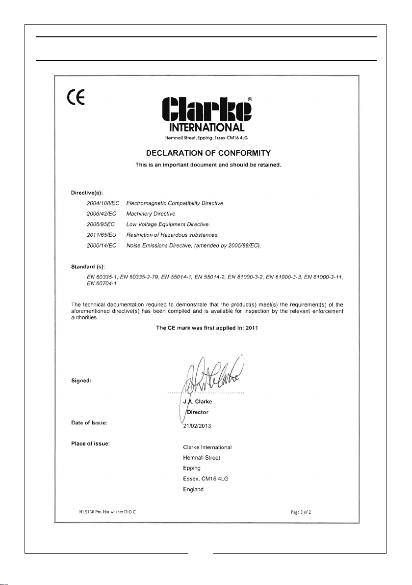
DECLARATION OF CONFORMITY
31
Parts & Service: 020 8988 7400 / E-mail: [email protected] or [email protected]
Page 32
 Loading...