

Page 1
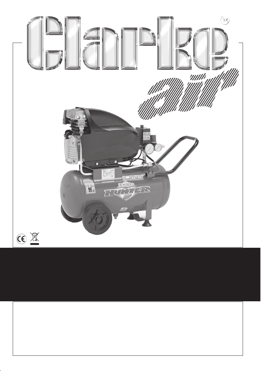
HUNTER 30
HUNTER 30
AIR COMPRESSOR
AIR COMPRESSOR
OPERATION & MAINTENANCE
INSTRUCTIONS
1
1011
©
Page 2

Thank you for purchasing this air compressor which is fitted with a 24 litre air
reservoir.
Please read this leaflet thoroughly and carefully follow all instructions. In doing
so you will ensure the safety of yourself and that of others around you, and you
can look forward to the compressor giving you long and satisfactory service.
GUARANTEE
This product is guaranteed against faulty manufacture for a period of 12 months
from the date of purchase. Please keep your receipt as proof of purchase. This
guarantee is invalid if the product is found to have been abused or tampered
with in any way, or not used for the purpose for which it was intended.
Faulty goods should be returned to their place of purchase, no product can be
returned without prior permission. This guarantee does not effect your statutory
rights.
CONTENTS PAGE
Safety Precautions ........................................................................... 3
Warning Symbols ............................................................................. 8
Electrical Connections ...................................................................... 9
Parts Identification............................................................................ 10
Assembly .......................................................................................... 11
Preparation for use ........................................................................... 13
Operating Instructions ...................................................................... 14
Routine Maintenance ....................................................................... 17
Troubleshooting ............................................................................... 19
Specifications ................................................................................... 20
Parts Diagram .................................................................................. 21
Parts List .......................................................................................... 22
Declaration of Conformity ................................................................. 23
2
Page 3
SAFETY PRECAUTIONS
WARNING!
As with all machinery, there are certain hazards involved with their operation
and use. Exercising respect and caution will considerably lessen the risk of
personal injury. However, if normal safety precautions are overlooked, or
ignored, personal injury to the operator, or damage to property may result. It
is in your own interest to read and pay attention to the following rules:
WARNING!
When using the air compressor, you should follow basic safety precautions
including the following to reduce the risk of personal injury. Make sure that
you have read all of the instructions before using the air compressor. Keep
this booklet with the compressor for future reference by the operator. Persons
who have not read this booklet should not use the air compressor.
WARNING!
Compressed air can be dangerous. Death or serious injury could result from
improper or unsafe use of this compressor. To avoid these risks, use your
common sense and follow these basic safety instructions. Compressed air
should never be inhaled as it may contain toxic vapours or solid particles.
Always work in good ventilation, especially when spraying paints or other
toxic substances and always use a suitable face mask. Do not spray near
sources of possible ignition.
WARNING!
Attachments, hoses and accessories must meet or exceed the maximum
pressure rating of this compressor.
If low pressure parts are used, the air pressure could cause them to explode
or fly apart, resulting in serious injury. Always take great care when releasing
the pressure and connecting/disconnecting tools.
WARNING!
This compressor must be connected to a power socket that is safeguarded
by a suitable circuit breaker or fuse.
3
Page 4

SAFETY PRECAUTIONS
TRAINING: Before use, you should be familiar with the instructions in this booklet.
In particular, you should pay attention to the procedure for stopping the
compressor in an emergency.
OPERATE THE AIR COMPRESSOR AT THE CORRECT VOLTAGE: Make sure that the
mains supply voltage is the same as the voltage shown on the rating plate.
PROTECT YOUR SELF AGAINST ELECTRIC SHOCK: Never operate the air
compressor in wet or damp locations.
DRESS PROPERLY: Loose clothing or jewellery may be caught in moving parts.
Always tie long hair back.
ALWAYS USE EYE PROTECTION: When operating the compressor, always use eye
protection, that protects both from the front and from the side.
PROTECT YOUR HEARING: Ear protection should be worn when operating this
compressor.
KEEP THE WORK AREA CLEAN: Clear the work area of all unnecessary tools,
debris and furniture.
KEEP VISITORS/CHILDREN AWAY: Do not allow visitors/children to handle the air
compressor or attachments and ensure that all people in the work area are
suitably dressed.
DO NOT ABUSE THE CABLE: Never pull on the cable when removing the plug
from the mains socket.
BREATHING QUALITY AIR: This compressor should not be used to supply
breathing quality air.
DO NOT ABUSE THE COMPRESSOR: Do not stand or place heavy objects on the
compressor.
SAFETY VALVE: Never remove or adjust the safety valve. Keep the safety valve
free from paint and dirt.
EXTENSION LEAD: Only use extension leads that are suitable for the work
environment. Extension leads must have an earth connection. Inspect the
extension lead regularly and replace if damaged.
4
Page 5

SAFETY PRECAUTIONS
AVOID UNINTENTIONAL STARTING: When connecting to the mains, make sure the
red button on top of the air compressor is in the off position.
MOVING THE COMPRESSOR: Always move the compressor using the
appropriate grips or handles.
ADEQUATE VENTILATION: The compressor should only be used in areas with
adequate ventilation and should not be exposed to heat, or used near
inflammable substances.
NEVER USE A DEFECTIVE AIR COMPRESSOR: If the compressor operates
unusually or makes strange noises, switch off immediately and purge the air
tank. Have the air compressor repaired by an authorised service centre.
NEVER OPERATE IN THE PRESENCE OF FLAMMABLE LIQUIDS OR GASES: The air
compressor produces sparks during operation.
ONLY USE WITHIN THE RECOMMENDED OPERATING TEMPERATURE RANGE: This
compressor should only be used at a temperature of between 0OC and 25OC.
NEVER OPERATE WITHOUT ALL GUARDS IN PLACE: Never operate without all
guards or safety features in place and in proper working order.
HANDLE THE AIR COMPRESSOR CAREFULLY: Operate the air compressor
according to the instructions contained within this instruction booklet. Children
or individuals unfamiliar with its operation should never operate this air
compressor.
DO NOT TOUCH HOT SURFACES: During operation, the motor, connections,
compressor body, cylinder head and tubes may get hot.
DISCONNECT THE AIR COMPRESSOR: Always disconnect the air compressor from
the mains power supply and release the pressure before performing
maintenance, changing any parts and when not in use.
DO NOT DIRECT THE AIR STREAM AT THE BODY: Do not direct the air stream at
people or animals. Compressed air can cause soft tissue damage and propel
dirt and other particles at high speed.
ONLY USE PARTS AND ACCESSORIES RECOMMENDED IN THIS MANUAL: The use
of unauthorised accessories or attachments is not permitted.
5
Page 6

SAFETY PRECAUTIONS
DO NOT USE THIS COMPRESSOR TO INFLATE SMALL, LOW-PRESSURE OBJECTS: Items
such as children’s toys or footballs can explode if over-inflated.
ONLY USE RECOMMENDED PARTS: To avoid the risk of bursting, only hoses with a
rated pressure of 10 bar, or more should be used. Never attempt to repair
faulty hoses.
AVOID KINKING OR TRAPPING THE AIR HOSE: Always replace faulty hoses never attempt a repair if a leak is detected.
STAY ALERT: Watch what you are doing, use common sense, and do not
operate the air compressor when you are tired. The air compressor should not
be used if you are under the influence of alcohol, drugs or any medication
that makes you drowsy.
KEEP ALL SCREWS AND COVERS TIGHTLY IN PLACE: Check the screws and
covers periodically.
STORE THE AIR COMPRESSOR PROPERLY: When not in use the air compressor
should be stored in a secure, dry place out of the reach of children.
KEEP THE AIR VENTS CLEAR: Keep the air vents clear and free from dust, wipe
regularly to maintain an adequate supply of clean air to the air compressor.
DO NOT CLEANING SOLVENTS: Do not use solvents or thinners such as petrol,
benzene, carbon tetrachloride or alcohol to clean the air compressor.
DO NOT MODIFY THE AIR COMPRESSOR: Do not attempt to modify the air
compressor, tank, fittings or attachments in any way. Doing so will invalidate
the guarantee and could result in personal injury.
DO NOT MODIFY THE TANK: Do not modify the tank or operate at pressures or
temperatures outside the limits stated in this booklet.
DRAIN TANK: Drain the tank after each use.
CLEANING THE COMPRESSOR: Keep the external surfaces of the tank clean.
Avoid impact damage and do not allow the tank to come into contact with
abrasive or corrosive materials.
6
Page 7

SAFETY PRECAUTIONS
USING THE COMPRESSOR FOR PAINTING:
• Do not work in enclosed areas or near naked flames.
• Make sure that the area in which you are working has good ventilation.
• Protect your nose and mouth with a suitable face mask.
• Always check the safety data sheets for substances being sprayed &
ensure manufacturers instructions are followed.
MOTOR HOUSING: Do not insert your fingers or other objects inside the motor
housing to avoid physical damage or damage to the compressor.
7
Page 8
WARNING SYMBOLS
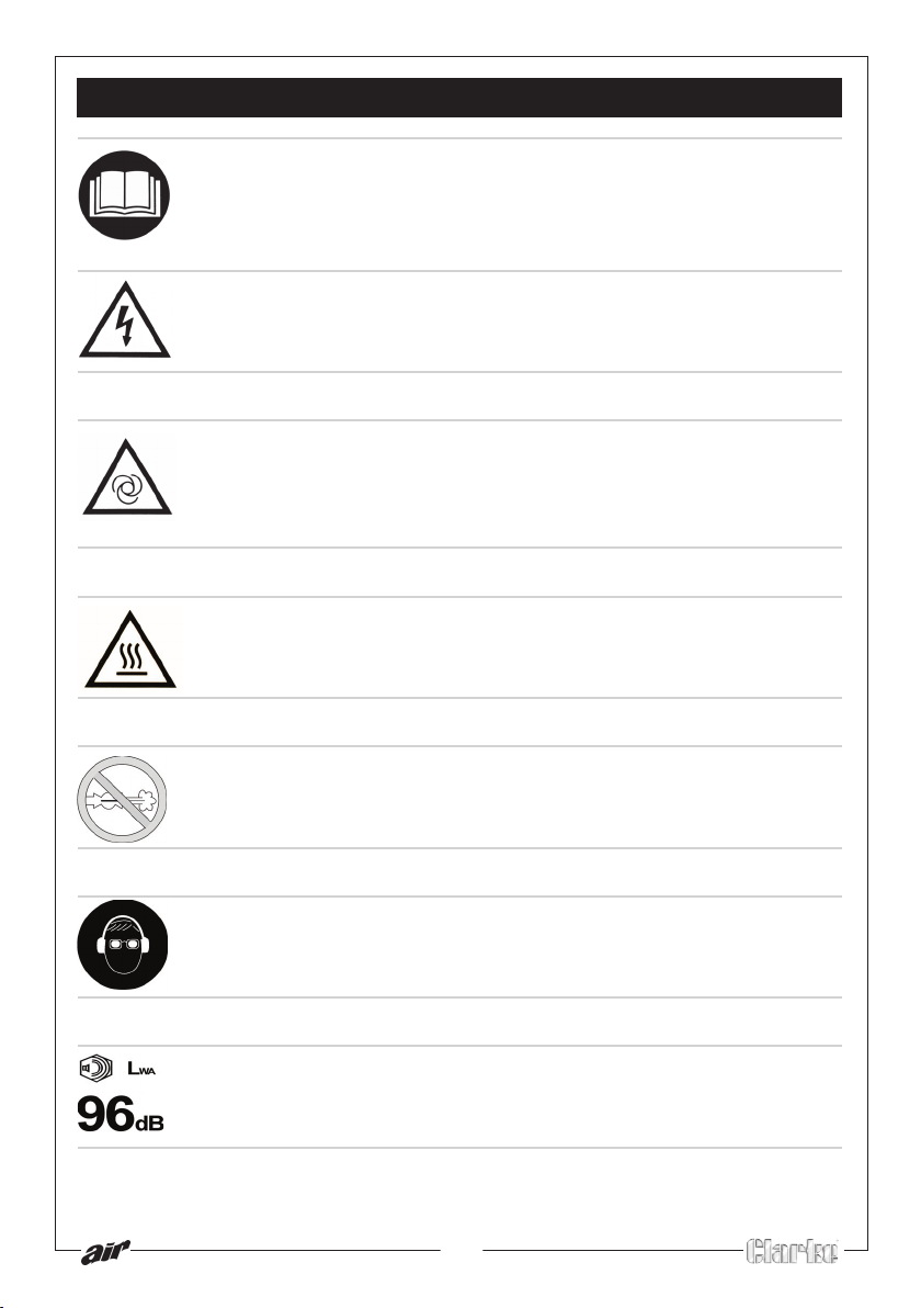
READ THIS INSTRUCTION BOOKLET CAREFULLY BEFORE
POSITIONING, OPERATING OR ADJUSTING THE
COMPRESSOR.
Risk of electric shock. The compressor must be disconnected
from the mains supply before removing any covers. Do not
use in a damp environment.
Risk of accidental start-up. The compressor could start
automatically in the event of a power cut and subsequent
reset. Do not carry the compressor while it is connected to the
power source, or when the tank is filled with compressed air.
This compressor contains surfaces which may reach a high
temperature during operation. Never operate with the motor
housing removed.
Air and condensation water can burst from the compressor
when the drain plug is removed.
Wear a safety goggles and ear protectors when using this
compressor
This compressor produces a high sound level during
operation. Ear protection should be worn.
8
Page 9

ELECTRICAL CONNECTIONS
Connect the mains lead to a standard, 230 Volt (50Hz) electrical supply through
an approved 13 amp BS 1363 plug, or a suitably fused isolator switch.
WARNING! THIS APPLIANCE MUST BE EARTHED
IMPORTANT: The wires in the mains lead are coloured in accordance with
the following code:
Green & Yellow - Earth
Blue - Neutral
Brown - Live
As the colours of the flexible lead of this appliance may not correspond with the
coloured markings identifying terminals in your plug proceed as follows:
• Connect GREEN & YELLOW cord to terminal marked with a letter “E”
or Earth symbol “ ” or coloured GREEN or GREEN & YELLOW.
• Connect BROWN cord to terminal marked with a letter “L” or
coloured RED.
• Connect BLUE cord to terminal marked with a letter “N” or coloured
BLACK.
If this appliance is fitted with a plug which is moulded onto the electric cable
(i.e. non-rewireable) please note:
1. The plug must be thrown away if it is cut from the electric cable.
There is a danger of electric shock if it is subsequently inserted into a
socket outlet.
2. Never use the plug without the fuse cover fitted.
3. When replacing a detachable fuse carrier, ensure the correct
replacement is used (as indicated by marking or colour code).
4. Replacement fuse covers can be obtained from your local dealer
or most electrical stockists.
FUSE RATING
The fuse in the plug must be replaced with one of the same rating (13 amps)
and this replacement must be ASTA approved to BS1362.
We strongly recommend that this machine is connected to the mains supply via
a Residual Current Device (RCD)
If in any doubt, consult a qualified electrician. DO NOT attempt any repairs
yourself.
9
Page 10
PARTS IDENTIFICATION
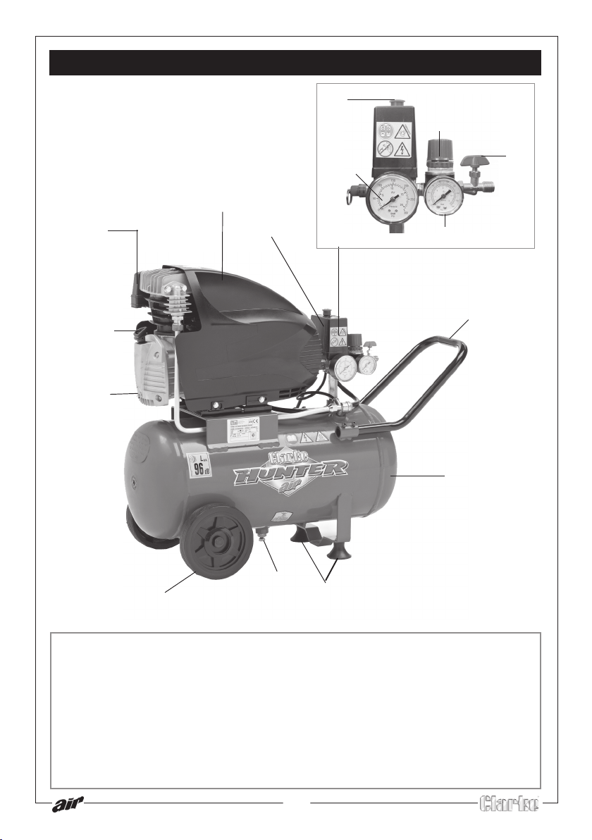
2
4
1
13
15
11
12
3
14
5
6
9
10
1 Air Filter
2 On/Off switch (red button)
3 Main reservoir pressure gauge
4 Output pressure regulator
5 Output pressure gauge
6 Handle
7 Support foot
8 Drain valve
8
7
9 Compressed air reservoir
10 Transportation wheel
11 Motor housing
12 Pressure regulator and cut-out
13 Oil dipstick
14 Outlet tap
15 Oil drain screw
10
Page 11
ASSEMBLY
3
3
WARNING!
Before assembling and using the air compressor, make sure that you have
read and understood all of the safety instructions.
Installation
Take care when lifting the compressor from the packaging.
CAUTION! Do not lift the compressor by the pressure regulator and cut-out.
Get assistance if necessary. This unit weighs 24 kg.
After removing the compressor from its packaging, check the integrity of the
unit, making sure it has not been damaged in transit.
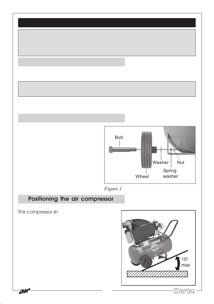
Fitting the transportation wheels
Fit the transportation wheels to either
side of the compressor as shown in
figures 1 using a 17mm spanner.
Bolt
Figure 1
Positioning the air compressor
This compressor should be positioned on a
stable, flat surface (or one with a maximum
inclination of 15O), See figure 2, and ensure
it is completely stable
Do not cover or box in the compressor.
Always position it at least 50cm from any
obstacle or wall
Make sure the compressor has good all
round ventilation.
11
Washer
Spring
Wheel
234567890123456789012
234567890123456789012
washer
Figure 2
Nut
15
max
0
Page 12
ASSEMBLY
Moving the air compressor
Before moving the compressor, switch off and disconnect it from the mains
power supply.
• Always use the handle.
• Do not lift by (or put strain on) fittings, valves or hoses.
• Take care when moving the compressor to avoid damaging the valves or
fittings.
The compressor is heavy, get assistance when lifting and moving this
compressor to avoid personal injury.
PREPARING FOR USE
Before connecting your compressor to the mains supply,
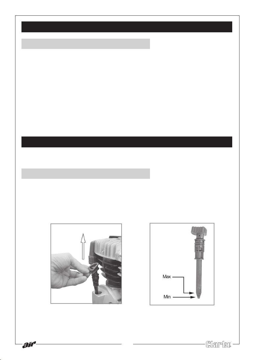
Check the Oil
1. Lift the dipstick out of the oil reservoir. See figure 3.
2. Ensure the oil level is between the min and max marks on the dipstick. See
figure 4.
• If needed top up the reservoir with Clarke SAE 40 compressor oil,
available from your Clarke dealer.
Figure 3
Figure 4
12
Page 13
PREPARING FOR USE
Before connecting your compressor to the mains supply, check the following:-
• The mains voltage is 230V.
• The ON/OFF switch is in the OFF (lower) position.
• The pressure regulator should be set at its lowest setting, i.e. turned fully
anticlockwise.
• If the compressor has not been used for 24 hours or so, open the drain
valve to drain any condensate which may have accumulated. When
clear, close the drain valve, finger tight.
IMPORTANT: If the air reservoir is under pressure, keep your hands well
away from the air being expelled. Remember, compressed air is
DANGEROUS!
WARNING!
Before connecting any airtool, make sure you have read and fully
understood the manufacturers instruction booklet for the tool being used.
Also ensure that the tool is compatible with the compressor and hose
specifications.
The pressure regulator must be used to adjust the output pressure.
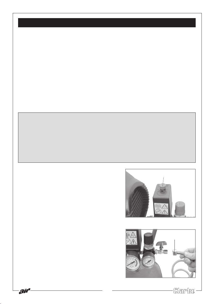
1 Ensure that the red On/Off switch is set to
the OFF position (pressed down). See
figure 5.
2. Insert the mains plug into the mains socket
and switch on the power.
3. Pull up the red ON/OFF switch up and run
the compressor (with the outlet tap open)
for 10 to 15 seconds, to allow the
distribution of the lubricating oil.
4 Attach the air hose to the outlet tap using
the hose nut. See figure 6.
13
On/Off Switch
Figure 5
Hose nut
Figure 6
Page 14

OPERATING INSTRUCTIONS
Switching the air compressor ON
The compressor will make a continuous loud noise when the tank is charging this is normal.
1. Lift the red On/Off switch located on
top of the pressure regulator and cutout.
• The compressor will charge the
main tank to 10 bar (145 psi) then
switch off.
• The compressor will restart
automatically whenever the
pressure in the main tank falls below
a certain level.
2. Check the operation of the safety
valve, under pressure, daily by pulling
the ring as shown in figure 7. Air should be released as you pull the ring and
stop when the ring is released.
• If the valve does not operate as described, or if the valve is stuck, it must
be replaced by qualified service personnel before using the compressor.
WARNING!
Figure 7
Do not remove or attempt to adjust the safety valve.
3. Select the pressure you need using the
pressure regulator. See figure 8.
4. Open the outlet tap.
14
Pressure
regulator
Output pressure
gauge
Figure 8
Page 15
OPERATING INSTRUCTIONS
Switching the air compressor OFF
To switch the air compressor off,
1. Close the outlet tap and press down on the on/off button (red button)
located on top of the pressure regulator and cut-out.
2. Switch off the mains supply and remove the plug.
• You should never leave the compressor air reservoir unattended while
under pressure.
• Always release the pressure from the reservoir when not in use or prior
to storage, as described in 'Draining the reservoir' on page 16.
Removing a tool from the air hose
WARNING!
Always set the pressure regulator to zero before attempting to remove or
replace a tool.
1 Stop the power supply by pressing down on the on/off button (red button)
located on top of the pressure regulator and cut-out.
2 Close tap and unscrew the tool.
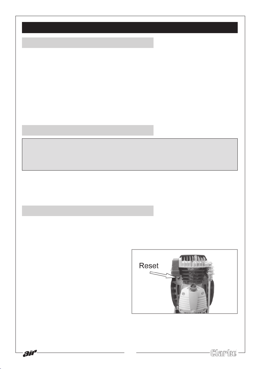
Reset button
This compressor is equipped with a thermal overload device, which operates
as a safety device to protect the motor.
When the motor overheats for any
reason, the thermal overload
automatically cuts the power thereby
preventing damage to the motor.
Wait around 5 minutes for the motor to
cool and press the reset button. See
figure 9.
If you restart the compressor and the
thermal overload activates again,
switch off the compressor, remove the
plug from the mains and have your
compressor checked by a qualified
service agent.
Figure 9
15
Page 16
OPERATING INSTRUCTIONS
Draining the reservoir
CAUTION! It is important to drain the reservoir before storage.
1 Pressing the red on/off button down to switch the air compressor off and
remove the plug from the mains supply.
• Place a suitable container beneath the compressor to catch any
condensate.
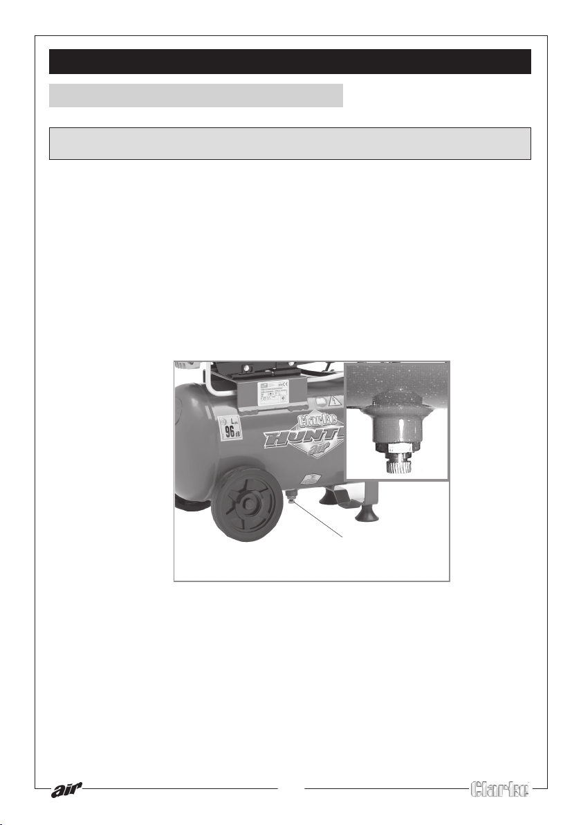
2 Carefully undo the drain valve anticlockwise until you hear a hissing noise,
this is the reservoir depressurising. See figure 10.
• When the reservoir pressure gauge indicates zero and the hissing has
stopped, tighten the drain valve again.
Figure 10
Drain valve
16
Page 17
ROUTINE MAINTENANCE
IMPORTANT: Before carrying out any of this service work, always
disconnect the compressor from the mains supply, drain the air receiver
and, if necessary, allow the machine to cool down before starting work.
Daily
Check Oil
Ensure the oil level is between the min and max marks on the dipstick. See page
12 and top-up if necessary - (use Clarke SAE 40 compressor oil, available from
your local dealer).
Drain the tank
After use, always open the drain valve to ensure that any liquid that may have
condensed, is drained off. See page 16.
Monthly
The air intake filter should be inspected on a MONTHLY basis, and more often in
dusty conditions,
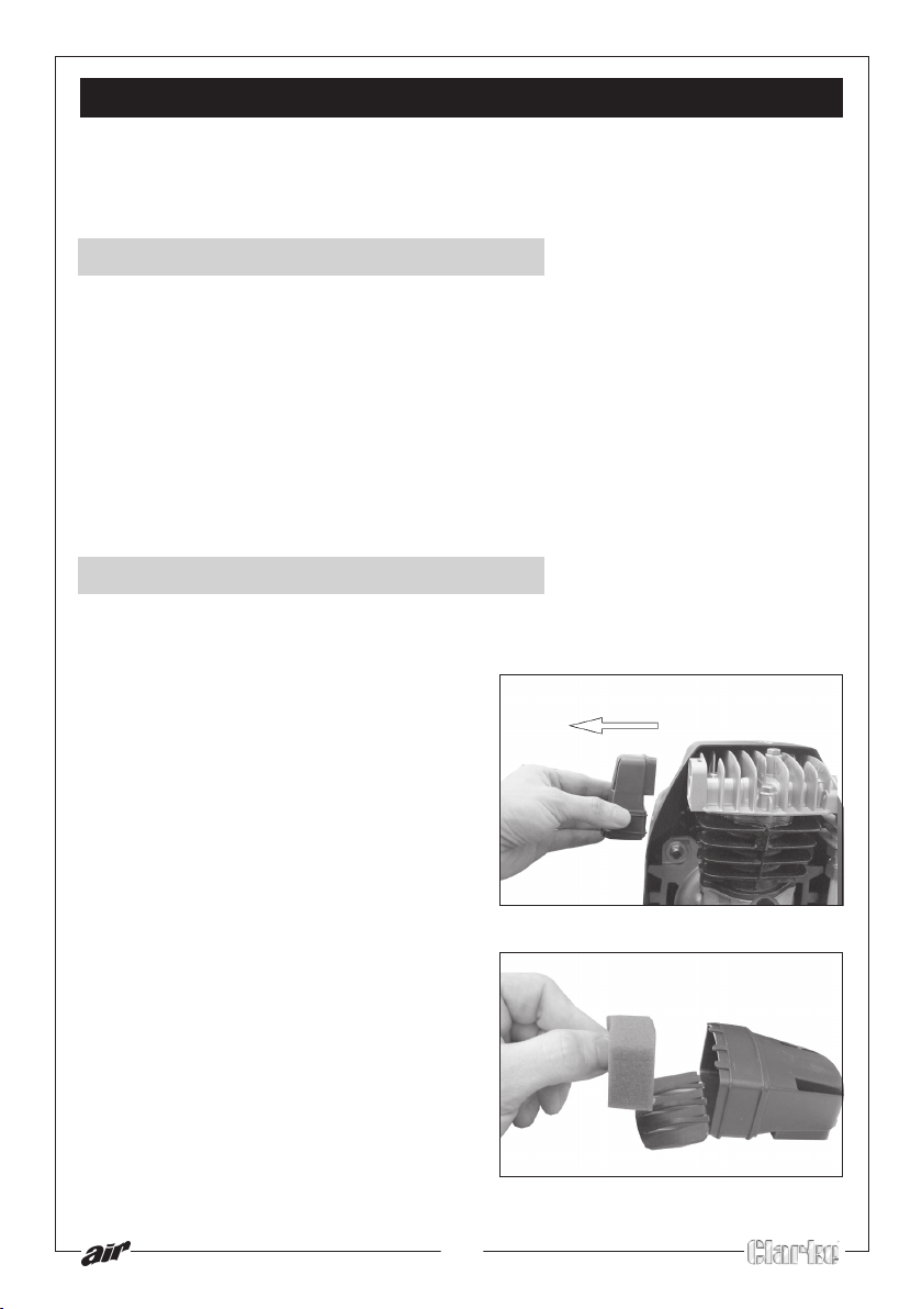
To clean the air intake filter,
1 Pull the filter cover away from the
compressor as shown. See figure 11.
2 Open the filter cover and remove the
sponge filter . See figure 12.
3 Clean the sponge and the filter cover
using a soft brush.
• If necessary, the sponge filter may
be gently washed in warm soapy
water,
• Rinse and allow the filter to dry
thoroughly before refitting.
5 Ensure that the filter and filter cover is
then placed back into its original
position.
• If any part of the filter is
damaged, you should obtain a
replacement.
17
Figure 11
Figure 12
Page 18
ROUTINE MAINTENANCE
Every six months
• Make sure that all bolts are securely tightened.
• Clean all the external parts of the compressor.
Oil
After the first 100 hours use, replace the oil completely using Clarke SAE 40
compressor oil. Then replace the oil after every 500 hours of operation or every 6
months.
To empty the oil from the machine, remove the oil drain screw from the
crankcase cover.
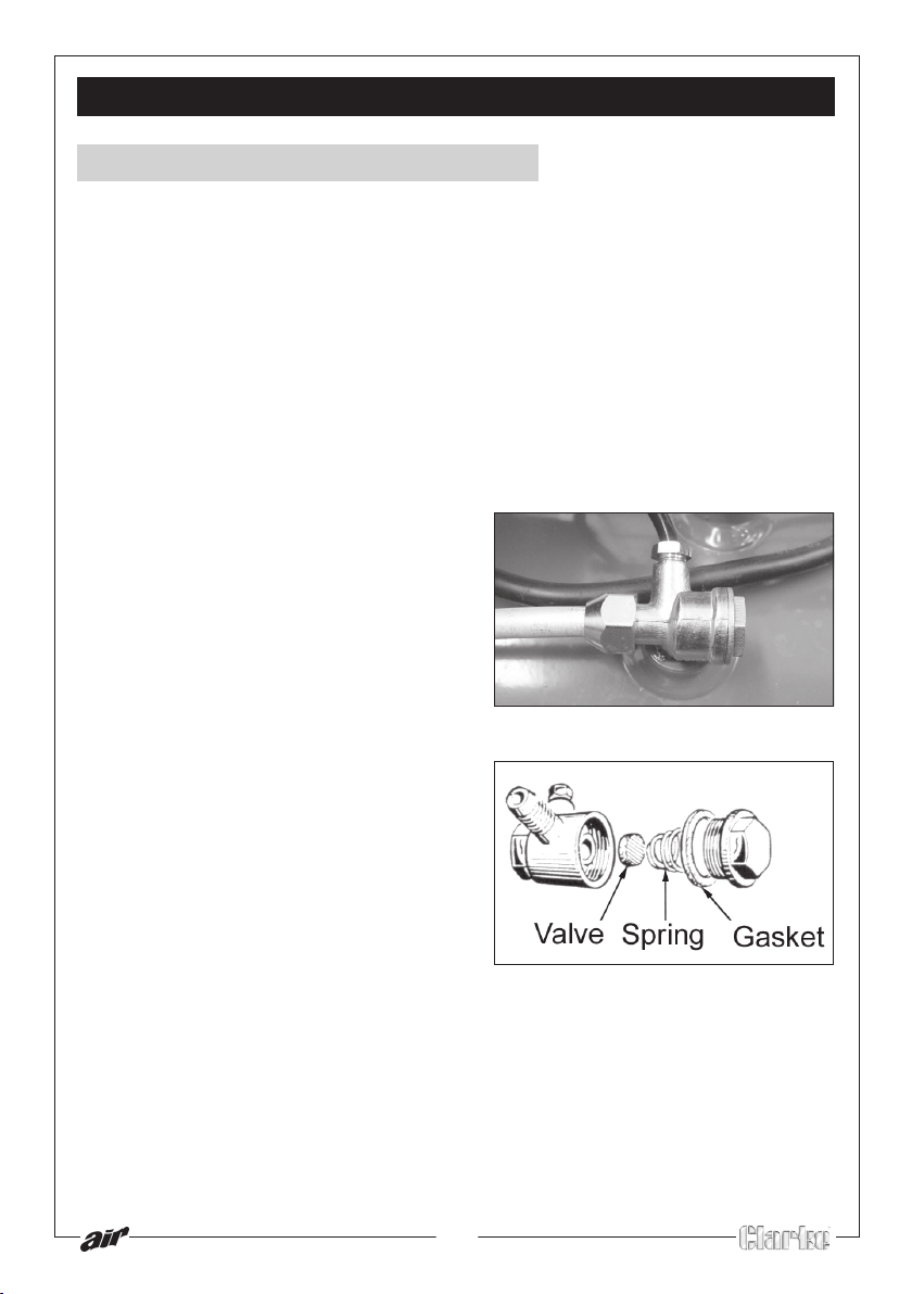
Non Return Valve
Examine the non-return valve, and
replace the gasket and valve if
necessary
Figure 13
18
Figure 14
Page 19
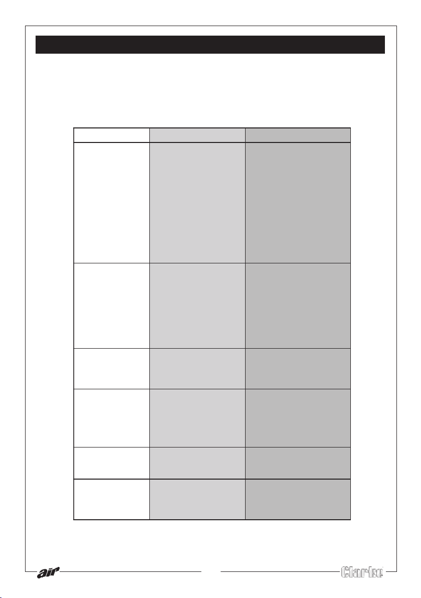
TROUBLE SHOOTING
With considerate use, your Clarke HUNTER Air Compressor should provide you
with long and trouble free service. Routine checks should be made on both the
electrical supply as well as on all the compressed air lines and connections. If
any fault appears, the reason for which is not immediately obvious, we
recommend that you contact your local Clarke dealer.
tluaF esuaC ydemeR
rosserpmocehT
seoddnadeppots
.tratston
.snoitcennocdaB
lacirtcelekcehC
dnanaelC.snoitcennoc
.yrassecensanethgit
hctiwstuotucdaolrevO
ytudrodeppirtsah
neebsahelcyc
.dedeecxe
.tuo
rosserpmocehT
seod
.ylisae
hcaerton
erusserpteseht
staehrevodna
.tratston
seodrosserpmoC
morfgnikaelriA
usserpeht
er
nehwevlavhctiws
sirosserpmoceht
.gninnurton
morferusserpriA
lliwrotalugereht
.tsujdaton
sirosserpmocehT
dnaysionyrev
cillatemasekam
.dnuosgnikconk
.nekorb
.nekorb
tnrubsgnidniwrotoM
daehrosserpmoC
evlavronwolbteksag
degrahcreviecerriA lepxeotevlavniardnepO
.evlavnruter-nonytluaF reviecerniardtsriF
nihtiwmgarhpaidehT
siydobrotalugereht
degamadrosserpmoC
.luahrevosdeendna
ehtgnisserp
.rotom
ebsecafrus
.relaed
.tnega
tiawdnaffohctiwS
erofebsetunim5xorppa
nottubteser
.niaganognihctiwsdna
ekralClacolruoytcatnoC
tnemecalperarofrelaed
otrosserpmocroftiaW
elbmessasid,nwodlooc
ynaecalperdnadaeh
.stnenopmocnekorb
erof
gnilaesllanaelcylluferaC
tbuodnifI.gnilbmessaer
ekralCruoytcatnoc
dluohsrosserpmoC.ria
erusserpnehwniagatrats
.isp59.xorppaotsecuder
evomeR.riafoyletelpmoc
,gulpdneevlaveht
evlavehtnaelcylluferac
dnateksagehtdnataes
.31e
rugiFeeS.elbmessaer
rotalugerecalpeR
otenihcamehtnruteR
ecivrestseraenruoy
CAUTION Do not attempt any repair or adjustment if you are uncertain as
to how it should be done. If you have any queries, contact your local
Clarke Dealer.
19
Page 20

SPECIFICATIONS
Electrical Supply ...................................... 230 V, 1 Phase 50Hz
Max. Operating Pressure ....................... 10 bar / 145 psi
Motor Rating ........................................... 2 HP
Air Displacement .................................... 8 cuft/min
Air Receiver ............................................ 24 litre
Net Weight .............................................. 24 kg
Dimensions ( L x W x H ) .......................... 710x 307x 590mm
Duty Cycle............................................... S1 (continuous)
Part No. .................................................... 2225407
Please note that the details and specifications contained herein, are correct
at the time of going to print. However, we reserve the right to change
specifications at any time without prior notice. Always consult the machine’s
data plate
When disposing of this product, ensure it is disposed of according to all local ordinances. It must
not be disposed of with general household waste.
20
Page 21
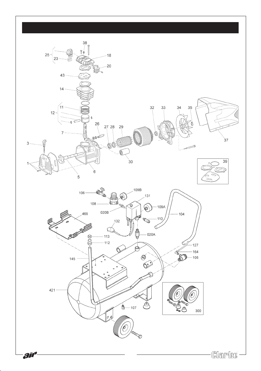
PARTS DIAGRAM
21
Page 22
PARTS LIST
NO. DESCRIPTION PART NO.
PUMP UNIT MK265-2M FN516CN01605
1 PUMP CASING COVER FN116CN0025
3 OIL DIPSTICK FN012089000
5 CRANKSHAFT FN116CN0017
6 CASING FN116120006
7 CONNECTING ROD FN116121005
11 PISTON RING SET FN216022002
12 COMPLETE PISTON FN416022004
14 CYLINDER FN116CN0015
20 MANIFOLD FN016NC0004
23 FILTERING ELEMENT FN017082001
25 INTAKE FILTER FN317082000
26 OVERLOAD CUTOUT FN008433000
27 BEARING FN033082000
28 SEAL RING FN010132000
29 ROTOR FN116093005
30 CONDENSER FN009200015
32 BEARING FN033005000
33 REAR COVER FN116120007
34 FAN FN116120008
35 CIRCLIP FN015083000
37 HOUSING FN116NC0003
38 AUTO DISCHARGE VALVE FN011000183
NO. DESCRIPTION PART NO.
39 GASKETS SET FN216CN0001
43 VALVE PLATE FN416CN0003
104 HANDLE FN168IQ0002
105 NON RETURN VALVE FN347092000
106 LINE COCK FN322007000
107 DRAIN COCK FN022085000
108 PRESSURE REDUCER FN319216000
109A PRESSURE GAUGE FN330007000
109B PRESSURE GAUGE FN330006000
110 SAFETY VALVE FN047206000
112 RING NUT FN116HP0011
113 NOSE CONE FN161535012
127 RILSAN PIPE FN046001000
131 PRESSURE SWITCH FN321087000
132 POWER CABLE BSI PLUG FN101GA0200
145 DELIVERY PIPE FN168QZ0006
164 L-FITTING FN011055000
300 WHEELS SET FN470QH0012
421 TANK FN168120001V
469 BASE PLATE FN168IQ0005V
020A NIPPLE FN199110140
020B NIPPLE FN011017000
SPARE PARTS AND SERVICE
For spare parts and service, please contact your nearest dealer, or Clarke
International, on one of the following numbers.
PARTS & SERVICE TEL: 020 8988 7400
PARTS & SERVICE FAX: 020 8558 3622
or e-mail as follows:
PARTS: [email protected]
SERVICE: [email protected]
22
Page 23
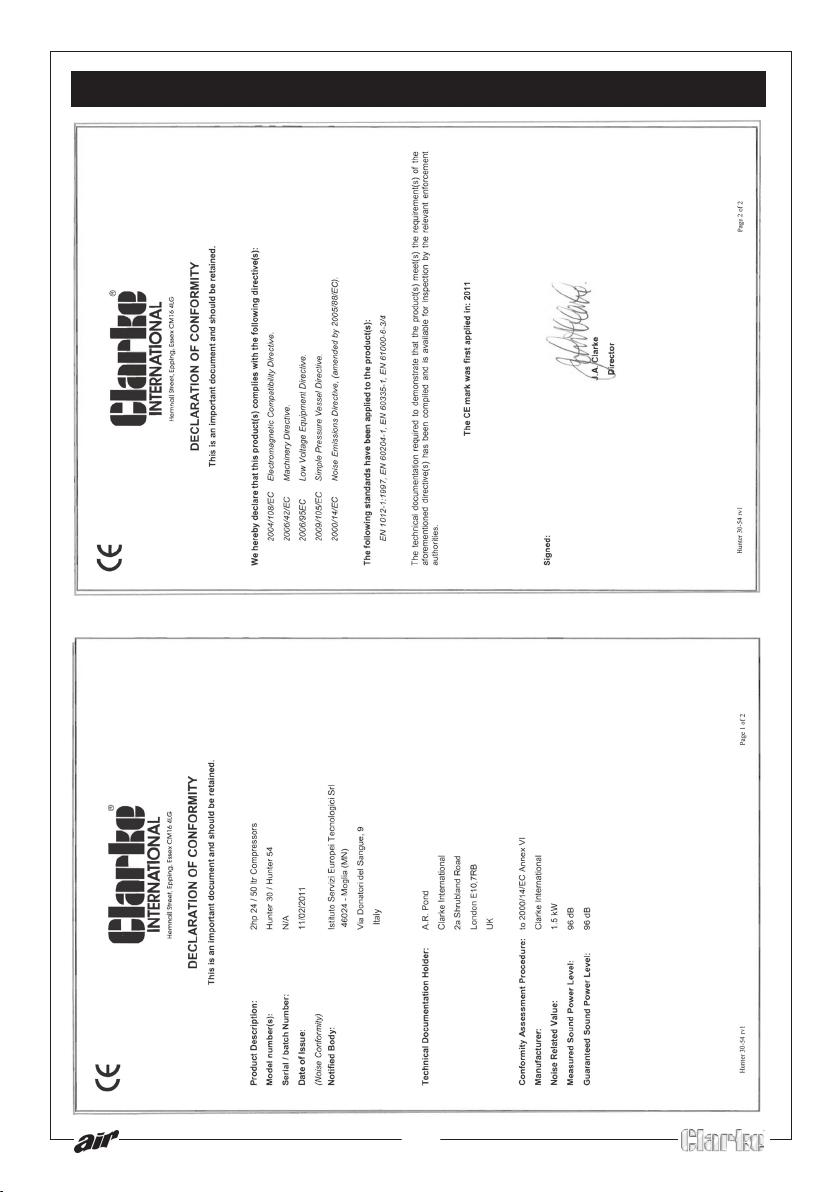
DECLARATION OF CONFORMITY
23
Page 24

 Loading...