

Page 1

SUBMERSIBLE
WATER PUMP
Model Nos.
HSE120 - 120A - 240 - 240A - 250A
& HSEC 400A
OPERATING & MAINTENANCE
INSTRUCTIONS
0598
Page 2
Thank you for purchasing this Clarke HSE Submersible Pump.
These highly efficient pumps are designed for pumping clean water, or water
containing sand or solids in suspension, depending upon the model (please see
below), and are ideally suited for draining ponds, pools, building excavations
etc.Water temperature must not exceed 35 C.
Before attempting to operate your pump, please read this instruction manual
thoroughly and follow all directions carefully. This is for your own safety and that
of others around you, and to help you achieve long and trouble free service from
your pump.
GUARANTEE
This product is guaranteed against faults in manufacture for 12 months from
purchase date. Keep your receipt as proof of purchase.This guarantee is invalid if
the product has been abused or tampered with in any way, or not used for the
purpose for which it is intended. The reason for return must be clearly stated. This
guarantee does not affect your statutory rights.
SAFETY PRECAUTIONS
1. These pumps are designed to pump WATER ONLY. Never use for pumping
flammable liquids or chemicals.
2. Never run the pump dry
3. An approved Residual Current Device (RCD) must be used when pumping
from ponds or swimming pools.
4. Your submersible pump may only be used for pumping water from a swim
ming pool when there is no person or animal in the pool.
5. Always disconnect the pump from the electrical supply before placing it
into, or removing it from the water, and before any cleaning or maintenance
of the pump.
6. Always use the moulded handle, with a rope or cord attached if necessary,
when lifting the pump. Do not lift the pump by the mains cable, or, where
fitted, the float switch cables.
7. DO NOT run the pump with the body exposed for longer than 10 minutes.
8. DO NOT install the pump on sand, or ground which is likely to shift.
9. Do not use the pump if the water is liable to freeze, as this can cause dam
age to the pump. Remove the pump from the water and store it in a frost
free location.
10. If the pump is to be used where there may be silt or mud (for example,
garden ponds), keep the pump clear of any sediment by standing it on a
platform or brick.
11. Always disconnect the pump from the mains supply before placing it into or
removing it from water, and before any cleaning or maintenance of the
pump.
2
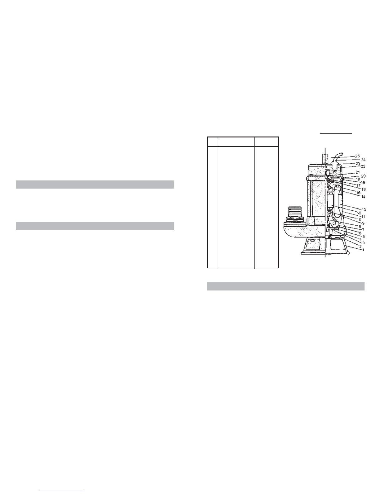
HSEC 400A
7
1 Strainer HG400A01
2 Strainer Packing HG400A02
3 Impeller HG400A13
4 Pump Casing HG400A04
5 Oil Seal HG400A05
6 Oil Cover HG400A06
7 Oil Cover Packing HG400A07
8 Mechanical Seal HG400A08
9 Motor Casing Pkg HG400A09
10 Lower Bearing HG400A10
11 Motor Casing HG400A11
12 Rotor Shaft HG400A12
13 Stator Coil HG400A13
14 Centrifugal Switch HG400A14
15 Thermal Overload HG400A15
16 Centrifugal Plate HG400A16
17 Upper Bearing HG400A17
18 Motor Casing Pkg HG400A18
19 Inside Cover HG400A19
20 Head Cover Pkg. HG400A20
21 Capacitor HG400A21
22 Cable Gland HG400A22
23 Gland Packing HG400A23
24 Power Cable HG400A24
25 Handle HG400A25
26 Outlet Discharge. HG400A26
No. Description Part No.
PARTS LIST & DIAGRAM
SPECIFICATIONS
Model No.
Outlet Dia. (in/mm) 1¼/32 2/50 2/50
Motor Output (Watts) 150 400 400
Head Max. (M) 7 12 8
Capacity Max. (L/min) 120 240 240
Head Continuous (M) 4 8 5.5
Capacity at Cont. Head (L/min) 80 130 100
Dimensions LxWxH (mm) 180x130x310 240x180x430 230x170x420
Weight (kg) 7 15 18
Cable (Mxmm2) 10x1.00 10x1.00 10x1.00
HSE 120
HSE 120A
HSE 200A
HSE 240
HSE 240A
HSE 250A
HSEC 400A
Page 3
you may damage the waterproof seal and invalidate your
guarantee. Repairs must be carried out by your CLARKE
dealer, or contact the CLARKE Service Dep’t, on 0181
556 4443.
If using this pump to pump out a garden pond,
please note that there is a small quantity of oil in
the pump seal. If the pump or seal is damaged,
possibly caused by running the pump dry, oil
may leak out, and appear as a film on the
surface of the water. Although harmless to
people, the oil must be cleared to prevent
any possible harm to pond life. Disconnect
the pump from the electrical supply,
remove it from the pond, and clear the
oil, then contact your CLARKE dealer for
advice.
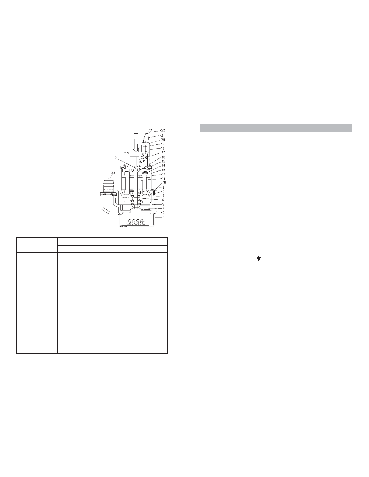
P ARTS LIST & DIAGRAM
HSE 200 & HSE 400 Series
6
Item Description
Part No.
HSE 120 HSE 120A HSE 240 HSE 240A HSE 250A
1 Strainer HG12001 HG120A01 HG24001 HG240A01 HG250A01
2 Centrifugal Switch HG12002 HG120A02 HG24002 HG240A02 HG250A02
3 Pump Housing HG12003 HG120A03 HG24003 HG240A03 HG250A03
4 Impeller HG12004 HG120A04 HG24004 HG240A04 HG250A04
5 Lip Seal HG12005 HG120A05 HG24005 HG240A05 HG250A05
6 Mechanical Seal HG12006 HG120A06 HG24006 HG240A06 HG250A06
7 Oil Chamber HG12007 HG120A07 HG24007 HG240A07 HG250A07
8 Bottom Motor Plate HG12008 HG120A08 HG24008 HG240A08 HG250A08
9 Lower Bearing HG12009 HG120A09 HG24009 HG240A09 HG250A09
10 ‘O’ Ring HG12010 HG120A10 HG24010 HG240A10 HG250A10
11 Rotor Shaft HG12011 HG120A11 HG24011 HG240A11 HG250A11
12 Stator HG12012 HG120A12 HG24012 HG240A12 HG250A12
13 Motor Case HG12013 HG120A13 HG24013 HG240A13 HG250A13
14 Overload Protector HG12014 HG120A14 HG24014 HG240A14 HG250A14
15 ‘O’ Ring HG12015 HG120A15 HG24015 HG240A15 HG250A15
16 Upper Bearing HG12016 HG120A16 HG24016 HG240A16 HG250A16
17 Capacitor HG12017 HG120A17 HG24017 HG240A17 HG250A17
18 Upper Cover HG12018 HG120A18 HG24018 HG240A18 HG250A18
19 Handle HG12019 HG120A19 HG24019 HG240A19 HG250A19
20 Gland Cover HG12020 HG120A20 HG24020 HG240A20 HG250A20
21 Cable Gland HG12021 HG120A21 HG24021 HG240A21 HG250A21
22 Power Cable HG12022 HG120A22 HG24022 HG240A22 HG250A22
23 Discharge Outlet HG12023 HG120A23 HG24023 HG240A23 HG250A23
3
ELECTRICAL CONNECTIONS
All models EXCEPT HSE 250A, should have their mains lead connected to a standard
230Volt (50Hz) electrical supply through an approved plug or a suitably fused
isolator switch. We recommend that these pumps be fitted with a Residual Current
Device (RCD).
NOTE: This is mandatory when pump is used for pumping swimming pools.
Model HSE250A must be connected to a protected 110V supply, through a suitably
approved connector. On no account must a 230V, 13amp (BS1363) plug be used.
NOTE: If a portable 110V transformer is used, make sure it has a rated capacity
sufficient to take the load of the pump.
In the event that the pump is hard wired into the electrical system, it must be
carried out in accordance with IEE regulations.
If used for draining swimming pools or ponds, the pump MUST be fitted with a
Residual Current Device (RCD), with a rated residual operating current of no
greater than 30mA.
WARNING: THIS APPLIANCE MUST BE EARTHED
IMPORTANT: The wires in the mains lead are coloured in accordance with the
following code: Green & Yellow - Earth
Blue - Neutral
Brown - Live
As the colours of the flexible cord of this appliance may not correspond with the
coloured markings identifying terminals in your plug proceed as follows:
Connect GREEN & YELLOW coloured cord to plug terminal marked with a
letter “E” or Earth symbol “ “ or coloured GREEN or GREEN & YELLOW.
Connect BROWN cord to terminal marked with a letter “L” or coloured RED
Connect BLUE cord to terminal marked with a letter “N” or coloured BLACK
The fuse in the plug for this appliance must be rated at 13 amps.
If this appliance is fitted with a plug which is moulded onto the electric cable (i.e.
non-rewirable) please note:
1. The plug must be thrown away if it is cut from the electric cable. There is a
danger ofelectric shock if it is subsequently inserted into a socket outlet.
2. Never use the plug without the fuse cover fitted.
3. Should you wish to replace a detachable fuse carrier, ensure that the correct
replacement is used (as indicated by marking or colour code).
4. Replacement fuse covers can be obtained from your local dealer or most
electrical
5. The fuse in the plug must be replaced with one of the same rating (13 amps)
and this replacement must be ASTA approved to BS1362.
IMPORTANT: If in doubt, consult a qualified electrician.
Page 4

4
FEATURES
The pumps are of rugged and durable construction, designed for long lasting
continuous operation, and the motor is provided with a built in overload protector.
Except for model HSEC 400A, the pumps should be used ONLY for pumping water,
or water containing small solids in suspension. NOT for pumping slurry, mud or heavily
polluted water.
The HSEC 400A is fitted with a Tungsten Carbide cutter, and is specially suited for
heavily polluted waste water and waste solids, such as sewage, light slurry, factory
waste etc.
Automatic Pumps, i.e. those fitted with a Float Switch, denoted by an ‘A’ suffix to
their model number, are suitable for permanent or semi-permanent installations,
eg. installations where it is necessary to maintain a water at a particular level.
As the water level rises, the switch will float, and start the pump. As the water level
falls, so will the float switch, until it stops the pump.
Float switches are factory set to provide the correct ON-OFF switching mode.
It is not recommended that these pumps be used for pumping drinking water, as
there is a remote possibility of water contamination due to leakage of pump
lubricant, should the pump malfunction.
INSTALLATION
The pumps are completely submersible, and should be placed in a vertical position,
on a solid flat surface. If this is not available, sit the pump on timber, or house
bricks, but ensure they are not likely to shift.
Automatic versions should be placed in a sump which has adequate dimensions
so as not to restrict the movement of the float switch.
Connect the outlet to the largest diameter hose possible, any restrictions will reduce
capacity, and put additional strain on the motor.
Take all necessary precautionsas described on page 2 before plugging in, and
switching ON.
SUITABLE HOSE, FOR ALL PUMPS, IS AVAILABLE FROM YOUR CLARKE DEALER
5
TROUBLESHOOTING
A. PUMP WILL NOT START
1. Manual type (i.e. without float switch)
1.1 Check to ensure Power is switched on.
1.2 Check fuse (consult an electrician if in doubt).
1.3 If extension lead is fitted, check connections (consult an electrician if in
doubt).
1.4 Internal thermal cut-out has not re-set. Leave for 5 minutes and try again.
1.5 The Impeller may be jammed. Disconnect from the mains supply, re
move the bottom strainer, and remove any objects that may be ob
structing the impeller. Replace the strainer and try again.
If the pump still fails to start, consult your CLARKE dealer for advice.
2. Automatic Type (with float switch)
2.1 Check all above.
2.2 Float switch may be jammed against side wall, or prevented from moving.
2.3 Water level too low - switch in OFF position.
B. PUMP WILL START BUT NOT PUMP
1. Water level too low.
2. Check to ensure strainer is not blocked.
3. Check to ensure impeller is not jammed as in 1.5 above.
4. Check to ensure impeller is not damaged, and replace if necessary.
5. The head may be too great, i.e. you are trying to lift the water too great
a distance for the pump to cope with. (See specification chart).
C. AUTOMATIC PUMP WILL NOT STOP
1. Float switch may be prevented from moving to the fully down position.
2. Float switch may be faulty. Consult your CLARKE dealer for advice.
MAINTENANCE
Check pump installation regularly to ensure the base inlet is clear of leaves or
other debris.
Note that these pumps are fitted with automatic thermal overload protection. If
the pump overheats due to an obstruction in the pump, or pumping warm water
for example, it will shut off automatically. Switch the pump OFF and disconnect
from the mains supply. Check for blockages and allow the motor to cool (at least
5 minutes) before attempting to re-start.
This pump should require no maintenance other than regular cleaning. If the pump
starts to show signs of wear or damage, contact your CLARKE dealer for advice.
Do not use the pump if there is any damage to the mains supply cable, or to the
float switch or its cable. Do not attempt to repair the pump yourself, as
 Loading...