

Page 1
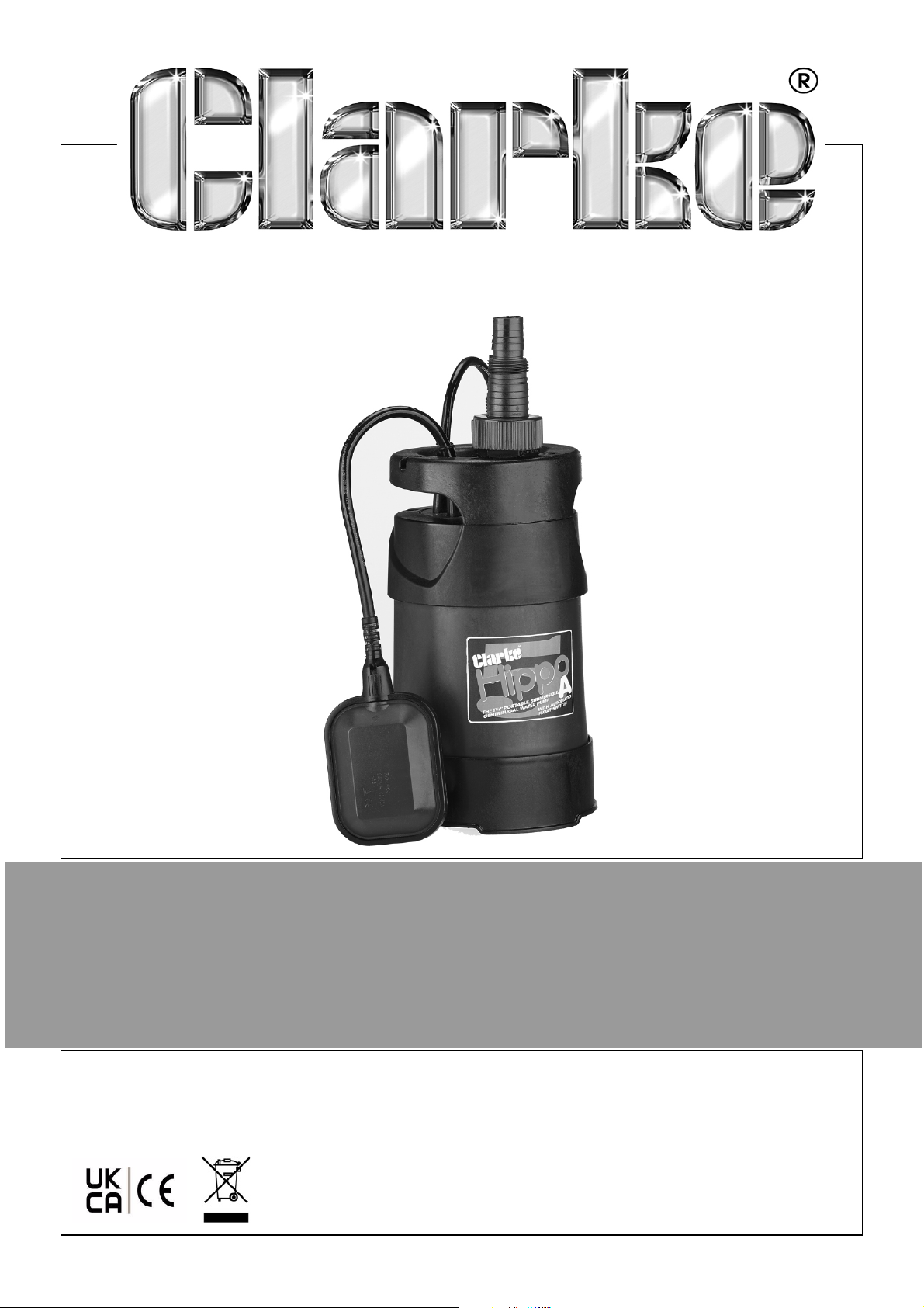
750W SUBMERSIBLE PUMP
MODEL NO: HIPPO 5A
PART NO: 7230536
OPERATION & MAINTENANCE
INSTRUCTIONS
ORIGINAL INSTRUCTIONS DL 0922 Iss 4
Page 2

INTRODUCTION
Thank you for purchasing this CLARKE 750W Submersible pump.
This pump is designed for pumping clean water only. It is NOT designed for
pumping slurry, sludge, mud or heavily polluted water, or any water
containing chemicals or other acidic contaminants including salt water.
GUARANTEE
This product is guaranteed against faulty manufacture for a period of 12
months from the date of purchase. Please keep your receipt which will be
required as proof of purchase.
This guarantee is invalid if the product is found to have been abused or
tampered with in any way, or not used for the purpose for which it was
intended.
Faulty goods should be returned to their place of purchase, no product can
be returned to us without prior permission.
This guarantee does not effect your statutory rights.
ENVIRONMENTAL RECYCLING POLICY
Through purchase of this product, the customer is taking on the
obligation to deal with the WEEE in accordance with the WEEE
regulations in relation to the treatment, recycling & recovery and
environmentally sound disposal of the WEEE.
In effect, this means that this product must not be disposed of with general
household waste. It must be disposed of according to the laws governing
Waste Electrical and Electronic Equipment (WEEE) at a recognised disposal
facility.
OVERLOAD SWITCH
These pumps are fitted with a thermal overload switch. If the pump overheats
for any reason, it will automatically switch the pump OFF. Once the pump has
cooled (at least 5-10 minutes), the pump will automatically restart.
2
Parts & Service: 020 8988 7400 / E-mail: [email protected] or [email protected]
Page 3

SAFETY INSTRUCTIONS
GENERAL
1. Read all instructions before use
and save these instructions for
future use.
2. An approved residual current
device (RCD) which has a
tripping current of less then 30mA
MUST be used for all operations.
3. The electrical supply must be the
same as that on the rating plate.
4. Always make sure that your
hands are dry when connecting
or disconnecting from the mains
supply.
5. Never pull the mains lead to
disconnect the pump from the
mains socket.
6. The mains plug must be kept
away from the water at all times.
7. Do not allow children or
unauthorised people to touch the
pump, cables or connections.
8. Disconnect the pump from the
mains supply when not in use.
9. If necessary have the pump
repaired by a qualified person.
PUMP SPECIFIC
1. Do not pump explosive /
flammable liquids or chemicals.
2. Never allow the pump to run dry
or operate out of the water.
3. Submersible pumps should always
be submerged and stored
vertically.
4. Disconnect the pump from the
mains supply before placing it
into or removing it from the water.
5. Always check the plug, and all
cables for damage before use.
6. Do not use the pump if
damaged. Refer to qualified
service personnel for repair.
7. Never carry or lower the pump by
the power cable or float switch
always use the handle or a rope
tied securely to the handle.
8. Never insert your fingers into the
pump whilst it is connected to the
mains.
9. Never use the submersible pump
in a swimming pool when there
are people or animals in the pool.
10. Keep the mains lead away from
heat, oil and sharp edges.
11. If you have to use an extension
lead with this product, it must be
designed for outdoor use and
incorporate a cable suitable for
use with Class I appliances.
12. Disconnect the pump from the
electrical supply and wear gloves
during servicing or maintenance.
Parts & Service: 020 8988 7400 / E-mail: [email protected] or [email protected]
10. Keep the pump clear of any
sediment by standing it on a
platform or brick or suspending it
at a suitable depth.
11. Do not use the pump if the water
is liable to freeze, as this can
cause damage to the pump.
Remove the pump from the
water and store it in a frost free
location.
3
Page 4
ELECTRICAL CONNECTIONS
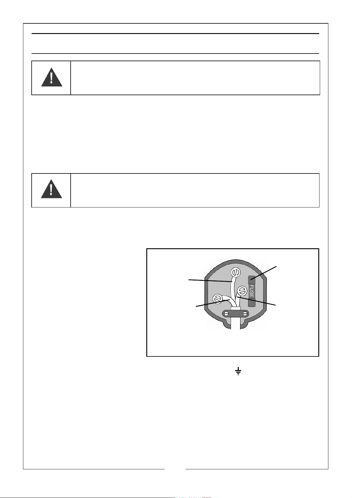
Plug must be BS1363/A approved.
Always fit
Ensure that the outer sheath of
Neutral
(Blue)
Live
(Brown)
Earth
(Green and
a 13 Amp
the cable is firmly held by the clamp
fuse.
Yellow)
WARNING: READ THESE ELECTRICAL SAFETY INSTRUCTIONS
THOROUGHLY BEFORE CONNECTING THE PRODUCT TO THE MAINS
SUPPLY.
Connect the mains lead to a standard, 230 Volt (50Hz) electrical supply
through an approved 13 amp BS 1363 plug, or a suitably fused isolator switch.
If the plug has to be changed because it is not suitable for your socket, or
because of damage, it must be removed and a replacement fitted, following
the wiring instructions shown below. The old plug must be discarded safely, as
insertion into a power socket could cause an electrical hazard
WARNING: THE WIRES IN THE POWER CABLE OF THIS PRODUCT ARE
COLOURED IN ACCORDANCE WITH THE FOLLOWING CODE:
BLUE = NEUTRAL BROWN = LIVE YELLOW AND GREEN = EARTH
.
If the colours of the wires in the power cable do not agree with the markings
on the plug.
• The BLUE wire must be
connected to the
terminal which is
marked N or coloured
black.
•The BROWN wire must
be connected to the
terminal which is
marked L or coloured
red.
• The YELLOW AND
GREEN wire must be
connected to the terminal which is marked E or or coloured green.
AN APPROVED RESIDUAL CURRENT DEVICE (RCD) WHICH HAS A TRIPPING
CURRENT OF LESS THAN 30 mA MUST BE USED.
If you are not sure, consult a qualified electrician. DO NOT try to do any
repairs.
Parts & Service: 020 8988 7400 / E-mail: [email protected] or [email protected]
4
Page 5
ASSEMBLY
Remove all packaging and make sure that the unit has no visible damage.
Dispose of all packaging appropriately.
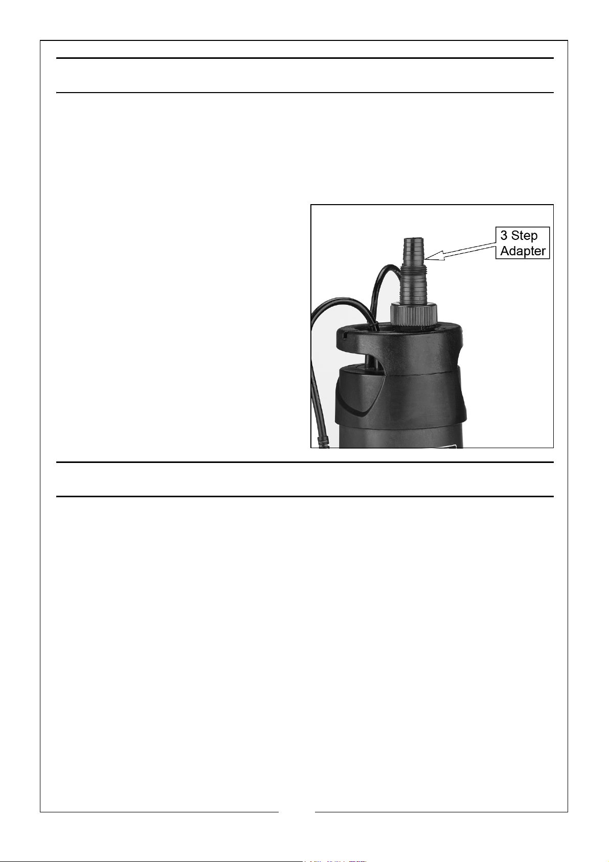
FITTING THE HOSE ADAPTER
• 3 step adapter 1¼" hose, 1" BSP, 1" hose.
1. Screw the 3 step adapter onto the
pump.
2. Trim the adaptor to the required
size.
• Reducing the hose diameter
will effect the maximum flow
rate.
• Suitable hoses are available
from your local Clarke dealer.
SETTING UP THE PUMP
POSITIONING THE PUMP
1. Place the pump on a flat surface in the area that you want to drain.
• If there is sediment in the operating area, the pump should be placed
vertically on house bricks, or similar.
• Ensure the pump is positioned with adequate space so that the
movement of the float switch is not restricted - recommended minimum
area of 50 x 50cm.
• ALWAYS raise and lower the pump using a rope attached to the lifting
handle, never lift/lower the pump by the mains lead.
• Take all necessary precautions as described on page 3.
5
Parts & Service: 020 8988 7400 / E-mail: [email protected] or [email protected]
Page 6

USING THE PUMP
WARNING: CHECK THE PUMP FOR DAMAGE BEFORE USE, DO NOT USE THE
PUMP IF IT IS DAMAGED IN ANY WAY.
WARNING: THE WATER BEING PUMPED WILL BE POLLUTED IF THIS PUMP
BECOMES DAMAGED AND LUBRICANT WITHIN THE PUMP ESCAPES.
1. Connect the mains plug to the mains supply.
• Always use a high sensitivity residual current device (RCD) which has a
tripping current of less then 30mA.
2. Switch the mains power supply on.
• The pump will begin to drain water.
• As the water level falls, so will the float switch, until it stops the pump.
• You can adjust the position at which the float switch lead clips to the
side of the pump. Adjusting the length of the float switch lead will
change the depth of water at which the pump will turn on or off.
3. When pumping is finished, disconnect the pump from the mains power
supply.
IMPORTANT: Do not allow the pump to run dry
6
Parts & Service: 020 8988 7400 / E-mail: [email protected] or [email protected]
Page 7
MAINTENANCE
WARNING: BEFORE CHECKING THE CONDITION OF THE PUMP, ENSURE IT
IS UNPLUGGED FROM THE MAINS SUPPLY. IF THE UNIT IS HARD WIRED,
ENSURE THE CIRCUIT BREAKER IS OPEN.
This pump should require no maintenance other than regular cleaning. If the
pump starts to show signs of wear or damage, contact your CLARKE dealer for
advice.
CLEANING
1. Check the pump installation regularly to ensure the water inlet is clear of
leaves or other debris. Take extra care to remove any debris from around
the impeller.
NOTE: Do not attempt to repair the pump yourself, as you may damage the
waterproof seal and invalidate your guarantee. Repairs must be
carried out by your CLARKE dealer, or contact the CLARKE Service
Department, on 020 8988 7400.
STORAGE
When the pump is not being used for extended periods, clean and dry it
thoroughly and store in indoors. if the pump is left in water, it must be run at
least once a week to prevent it from seizing up.
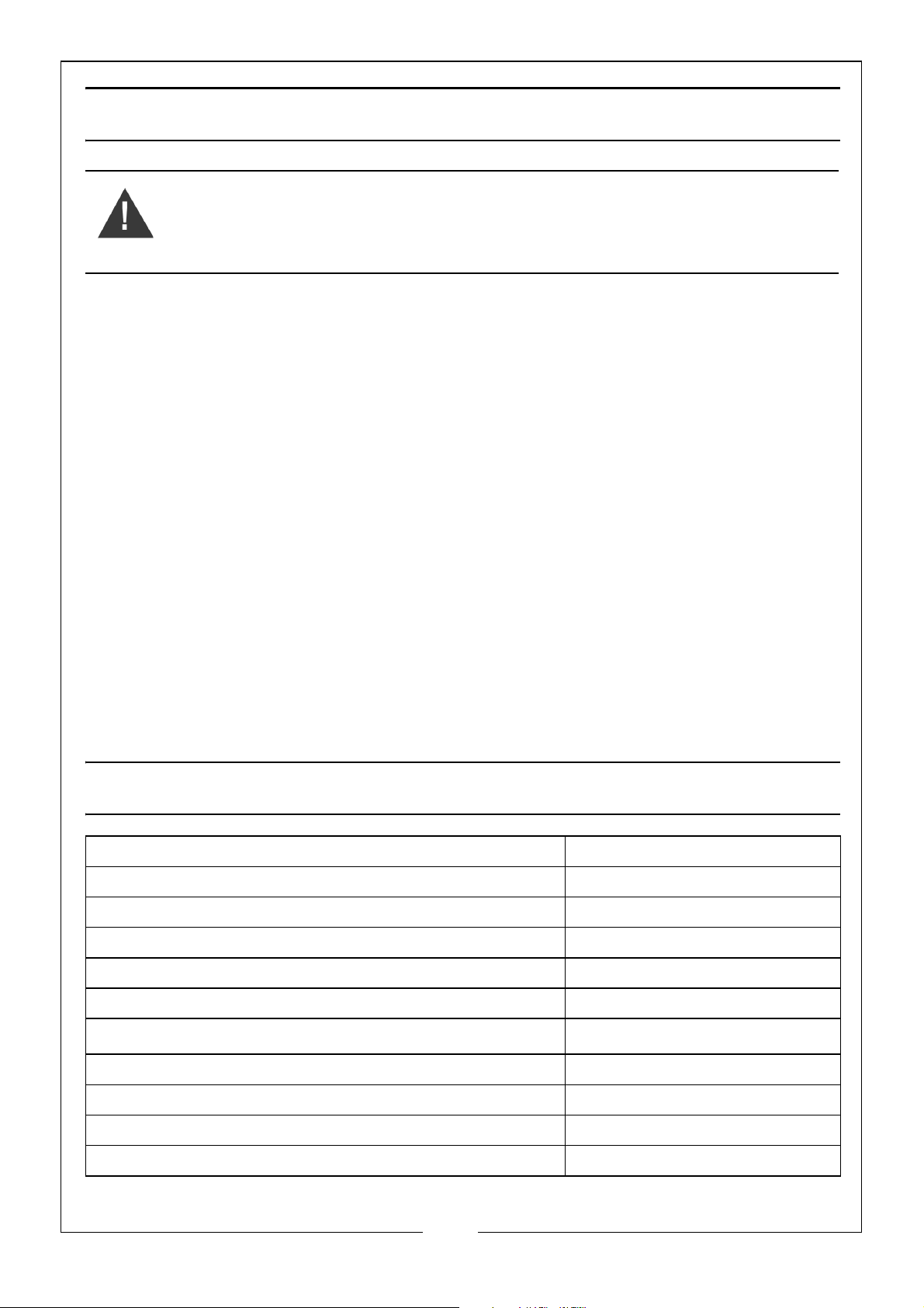
SPECIFICATIONS
Voltage 230V~50Hz
Outlet Thread Diameter 1¼“ BSP
Power 750W
Maximum Head Height 8.5 m
Maximum Depth 7 m
Maximum Flow 208 l/min
Maximum Water Temperature
Maximum Particle Size Clean Water Only
35
o
C
Weight 5.3 kg
Cable Length 10 m
Dimensions (D x W x H) 166 x 166 x 280 mm
7
Parts & Service: 020 8988 7400 / E-mail: [email protected] or [email protected]
Page 8

TROUBLESHOOTING
PROBLEM SOLUTION
PUMP WILL
NOT START
PUMP WILL
START BUT NOT
PUMP
1. Make sure that the power is switched on.
2. Check fuse (consult an electrician if in doubt).
3. If an extension lead is fitted, check connections (consult
an electrician if in doubt).
4. Internal thermal cut-out has not re-set. Leave for 5-10
minutes and try again.
5. The impeller may be jammed. Disconnect from the mains
supply and remove any objects that may be obstructing
the impeller.
6. Float switch may be jammed against side wall, or
prevented from moving.
7. If the pump still fails to start, consult your CLARKE dealer
for advice.
1. Check that the inlet is not blocked.
2. Check that the outlet is not clogged or obstructed.
3. The head may be too great, i.e. you are trying to lift the
water too great a distance for the pump to cope with.
(“Specifications” on page 7).
4. Air bubble in the pump, produced during immersion.
immerse the pump again, at an angle, and shake it whilst
lowering to remove any air trapped in the system.
5. Impeller may be damaged - Consult your CLARKE dealer.
PUMP WILL
NOT STOP
PUMP STOPS
RUNNING
If this does not solve your problem, please contact the Clarke service
department.
Parts & Service: 020 8988 7400 / E-mail: [email protected] or [email protected]
1. Float switch may be prevented from moving to the fully
down position.
2. Float switch may be faulty. Consult your CLARKE dealer
for advice.
1. Thermal overload has operated. Leave for 5-10 minutes
and try again.
2. Pump has run dry, or float switch has cut in.
3. A foreign object has jammed the impeller.
8
Page 9
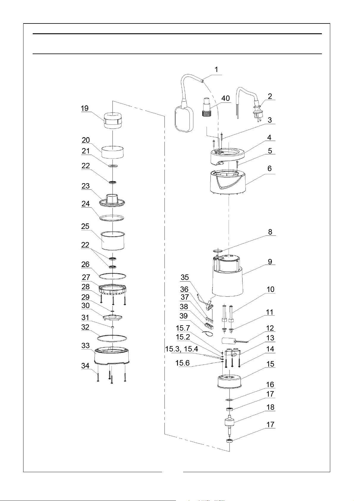
PARTS LIST & DIAGRAM
9
Parts & Service: 020 8988 7400 / E-mail: [email protected] or [email protected]
Page 10
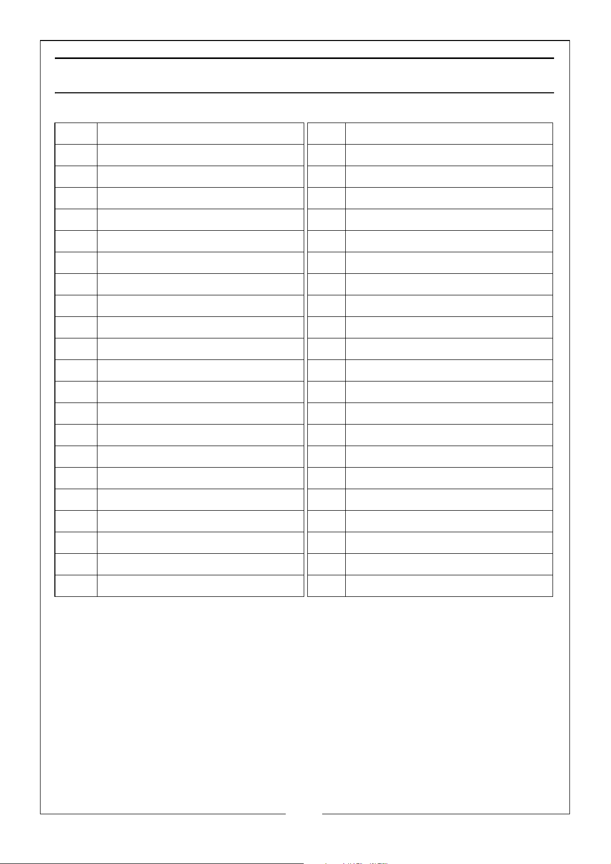
PARTS LIST
1 Mains Cable 19 Stator
2 Float Switch 20 Bushing
3 Self Tapping Screw 21 Gasket
4 Handle 22 Skeleton Seal
5 Self Tapping Screw 23 Aluminium Bushing
6 Cover Plate 24 O-ring
8O-ring 25Front Cover
9 Rear Pump Housing 26 O-ring
10 Cable Sheath 27 O-ring
11 Cable Gland 28 Self Tapping Screw
12 8uf Capacitor 29 Adjustable Washer
13 Cable Block 30 Impeller
14 Customized Self Tapping Screw 31 Nut
15 Rear Cover 32 O-ring
15.2 Gasket 33 Pump Base
15.3 Earth Wire (Yellow/green) 34 Self Tapping Screw
15.4 Lug Plate 35 Ground Cover
15.6 Gasket 36 Nylon Secure Pressing Cap
15.7 Bolt 37 Nylon Secure Pressing Cap
16 Wave Washer 38 Rubber Clip
17 Bearing 39 Ribbon
18 Rotor 40 Outlet Connector
Part number = (DHHIPPO5A + the number of the part)
10
Parts & Service: 020 8988 7400 / E-mail: [email protected] or [email protected]
Page 11
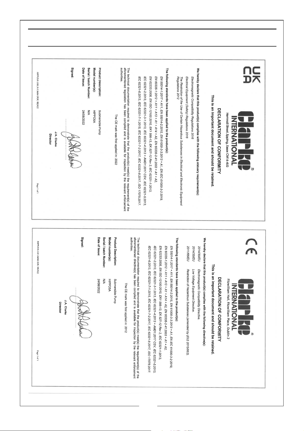
DECLARATION OF CONFORMITY
11
Parts & Service: 020 8988 7400 / E-mail: [email protected] or [email protected]
Page 12

 Loading...