

Page 1
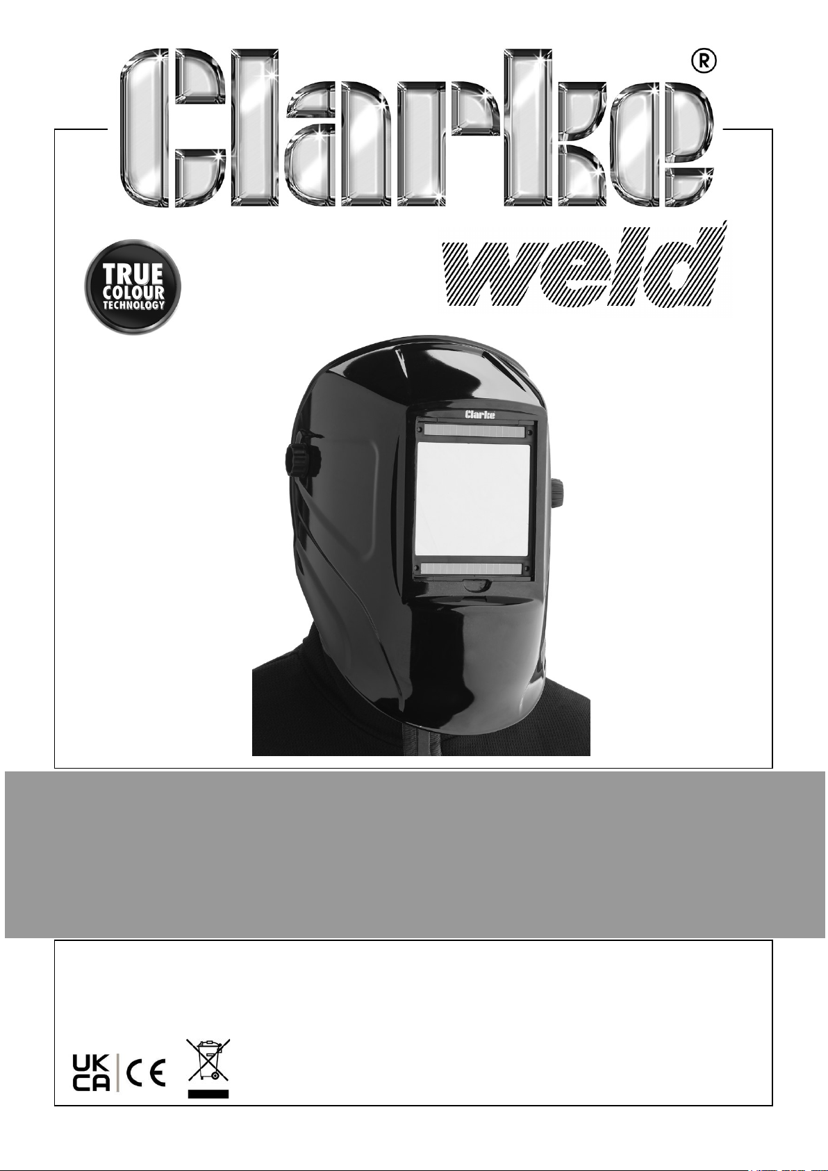
ARC ACTIVATED HEADSHIELD
MODEL NO: GWH8
PART NO: 6000714
OPERATION & MAINTENANCE
INSTRUCTIONS
ORIGINAL INSTRUCTIONS GC02/25-Rev 1
Page 2
INTRODUCTION
Thank you for purchasing this CLARKE Headshield. Before attempting to use this
product, please read this manual thoroughly and follow the instructions carefully. In
doing so you will ensure the safety of yourself and that of others around you, and you
can look forward to your purchase giving you long and satisfactory service.
GUARANTEE
This product is guaranteed against faulty manufacture for a period of 12 months from
the date of purchase. Please keep your receipt which will be required as proof of
purchase.
This guarantee is invalid if the product is found to have been abused or tampered
with in any way, or not used for the purpose for which it was intended.
Faulty goods should be returned to their place of purchase, no product can be
returned to us without prior permission.
This guarantee does not effect your statutory rights.
TECHNICAL DATA
Viewing field (W x H) 100 X 93 mm
Shade available in Light State DIN4
Shade available in Dark State DIN 5-9 / 9-13
UV/IR protection Max shade DIN16
Operating temperature range
Weight 0.56 kg
Switching time from light to dark 1/25,000 second or 0.04 m/s
Delay time from dark to light 0.15 - 0.08 second
Lens power control Manual step-less control
-5oC - +55oC
Power supply Solar Cells / Lithium Battery type Cr2032
Construction material Plastic (nylon)
2
Parts & Service: 020 8988 7400 / E-mail: [email protected] or [email protected]
Page 3
SAFETY PRECAUTIONS
This mask is not suitable for laser welding, laser cutting or overhead welding
applications or for oxy-acetylene.
• The protective plate in this headshield is breakable and will not protect against
impact hazards.
• This headshield is designed for use in grinding, arc welding or cutting applications
such as MIG/MAG, TIG, MMA, Plasma Arc, and Carbon Arc.
• Use this headshield for face and eye protection against harmful rays, sparks and
spatter from welding and cutting.
• NEVER place this product on a hot surface.
• In the event of failure, the headshield gives protection against UV and IR
radiation.
• DO NOT make any modifications to this product. Protection can be seriously
impaired if modifications are made.
• When necessary, use identical replacement parts. This will ensure that the safety
of the product is maintained.
• DO NOT use without the protective plate installed. DO NOT use if any part of the
headshield is cracked or broken.
• DO NOT use this headshield for welding outside the range of DIN 9-13. Harm to
the eyes and impaired eyesight may result. ALWAYS select the correct setting
before use.
ENVIRONMENTAL RECYCLING POLICY
Through purchase of this product, the customer is taking on the obligation
to deal with the WEEE in accordance with the WEEE regulations in relation
to the treatment, recycling & recovery and environmentally sound disposal
of the WEEE.
In effect, this means that this product must not be disposed of with general
household waste but according to the laws governing Waste Electrical and Electronic
Equipment (WEEE) at a recognised disposal facility.
The light source contained in this worklight has a life expectancy of approximately
30,000 hours after which the worklight should be disposed of in an environmentally
responsible way.
The Lithium Ion battery falls under the Waste Batteries and Accumulators Regulations
2009 and should be disposed of in a controlled manner.
3
Parts & Service: 020 8988 7400 / E-mail: [email protected] or [email protected]
Page 4
PREPARATION
ADJUSTING THE HEADBAND TO FIT
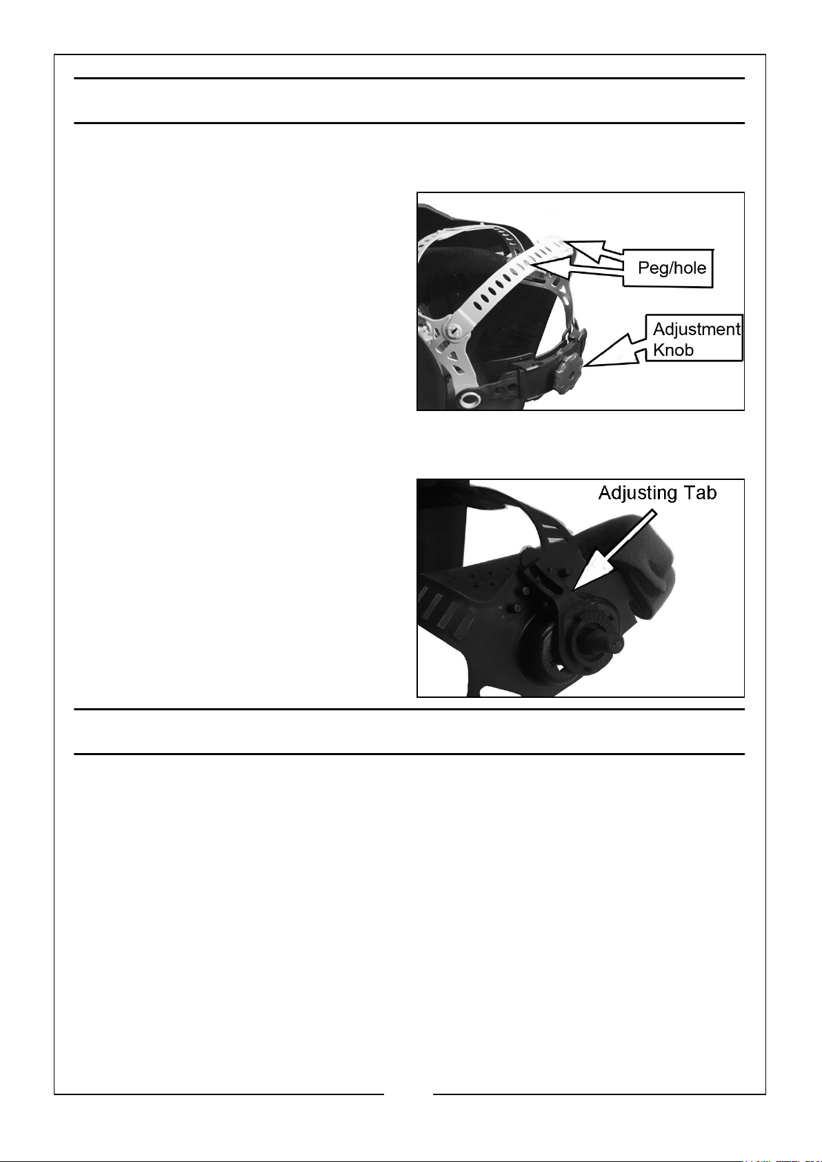
1. The headband should be adjusted
both in diameter and height to fit the
wearer’s head. To do this, press in
and turn the adjustment knob on the
back of the headband either left or
right to expand or contract the
headband.
2. The top headbands can be adjusted
by bending the strap and positioning
the pegs in the appropriate hole in
each headband.
3. The working position of the headshield and its raised position can be pre-set.
4. Loosen the adjusting nuts until you
can lift the adjusting tab and position
it on the pins on the backing plate to
set the headband range of
movement. Tighten the adjusting nut
when satisfied.
• You can remove the headband
completely from the headshield by
unscrewing the side knobs.
USING THE HEADSHIELD
1. The lens will be set to Light DIN 4 state, & you will be able to see the workpiece.
The lens will automatically darken when an arc is struck.
2. Test the lens by striking an arc on the workpiece for the first time. Check also that
the outer screen and lens are clean and clear at all times.
3. Change the shade setting as required using the shade adjustment knob as
described on page 5. Refer to the table on page 7.
4
Parts & Service: 020 8988 7400 / E-mail: [email protected] or [email protected]
Page 5
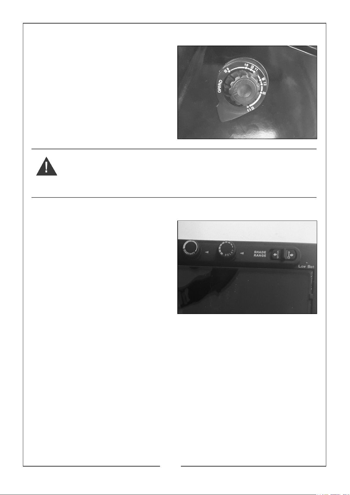
SELECTING WELD OR GRIND SETTING
The headshield has a ‘GRIND’ setting, on
the outside selector knob. When set to
‘GRIND’ the auto darkening function is
disabled.
The headshield then provides eye and
face protection for sparks and airborne
particles created during grinding
operations.
WARNING: IT IS ESSENTIAL THAT AFTER USING THE HEADSHIELD
IN GRINDING MODE, IT SHOULD BE RETURNED TO THE WELD
SETTING BEFORE WELDING. FAILURE TO DO THIS COULD LEAD TO
EYE INJURY. MAKE A HABIT OF RETURNING THE SWITCH TO THE
WELD SETTING.
DELAY TIME ADJUSTMENT
The delay time is the time taken to
switch back from fully dark to fully light
and is selected using the knob in the
centre of the headshield.
1. Set the minimum (0.1-0.25 sec)
when spot welding, or doing short or
seam welding work.
2. Set the delay to medium for most
welding operations.
3. Set the maximum (0.85-1.0 sec)
when doing high current welding.
SENSITIVITY
The sensitivity can be adjusted using the knob on the left hand side of the headshield
according to the type of welding and the background light. The mid range selection is
suitable for most indoor and outdoor welding.
1. Select maximum for low current welding or when working in low light conditions,
especially when welding argon arc with a low current.
2. Select minimum for high current welding or working in a brightly lit environment.
SELECT THE SHADE SETTING
WARNING: DO NOT USE FOR WELDING OUTSIDE THE RANGE OF DIN 9-13.
INJURY TO THE EYES & LOSS OF EYESIGHT MAY BE CAUSED.
5
Parts & Service: 020 8988 7400 / E-mail: [email protected] or [email protected]
Page 6
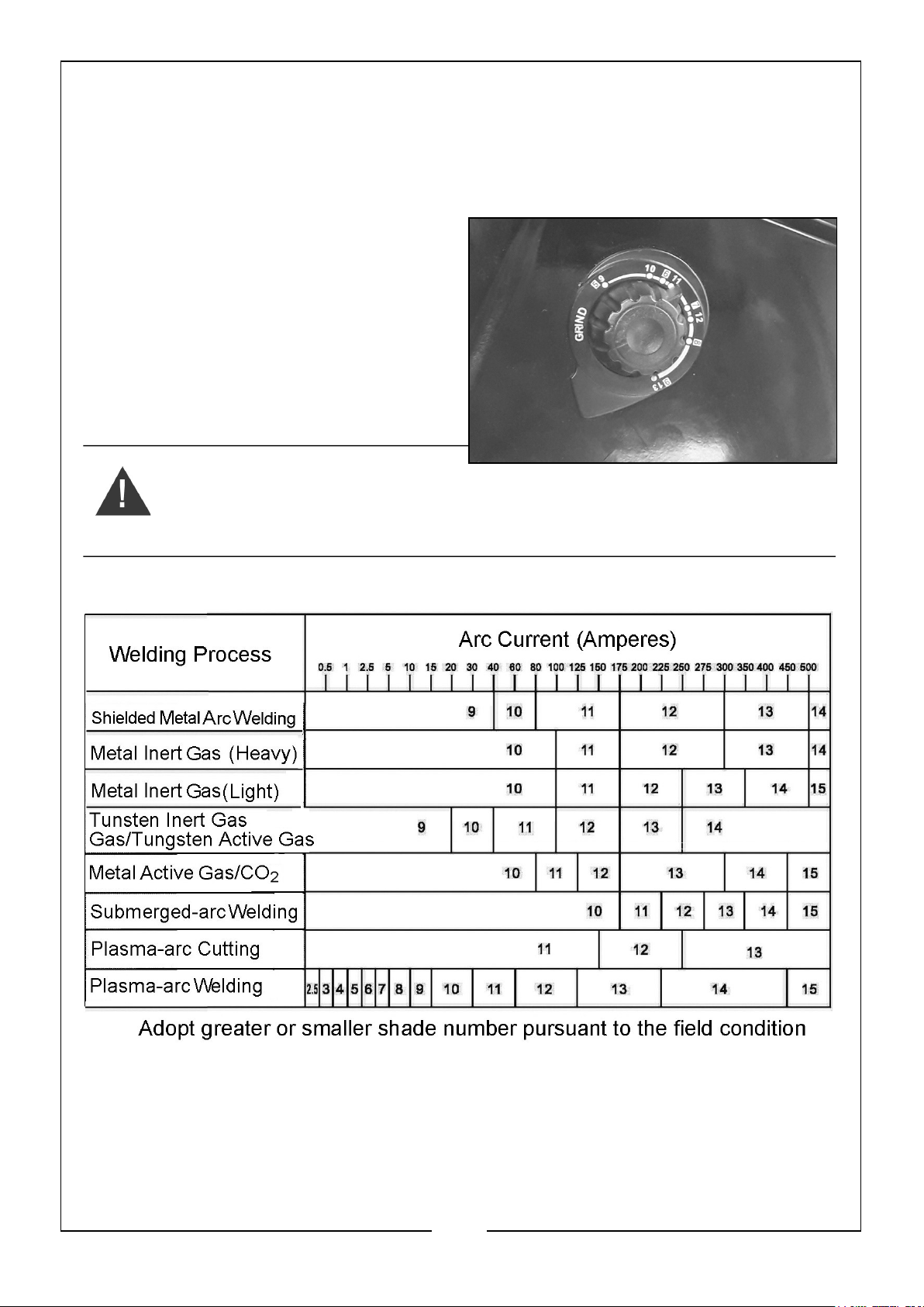
On striking an arc, the light created will activate the solar cell and the window will
automatically darken to a preset level. The lithium battery will provide the necessary
energy to operate the headshield when there is no arc light. You can adjust this shade
level using the shade adjustment knob on the side of the headshield, corresponding
to the type of welding process.
1. Set the shade selector to the required
setting.
2. During the welding operation the lens
will automatically darken to the preset shade. On removal of the arc, the
lens will return to the light state.
Check the table to determine which you
should select.
WARNING: IT IS ESSENTIAL THAT AFTER USING THE HEADSHIELD
IN GRINDING MODE, IT SHOULD BE RETURNED TO THE CORRECT
SETTING BEFORE WELDING. FAILURE TO DO THIS COULD LEAD TO
EYE INJURY.
Shade numbers according to BS 379, DIN 4647-1 and EN 169
6
Parts & Service: 020 8988 7400 / E-mail: [email protected] or [email protected]
Page 7
CARE & MAINTENANCE
Damaged components must be replaced immediately to avoid risk of eye and face
injuries. Periodically inspect the filter cartridge and lenses. Cracked, pitted or
scratched lenses reduce vision and seriously reduce the level of protection and should
be replaced with genuine, certified spare parts.
NEVER use sharp tools to remove foreign material sticking to the outer lens cover.
This may cause damage leading to poor function and invalidate the warranty.
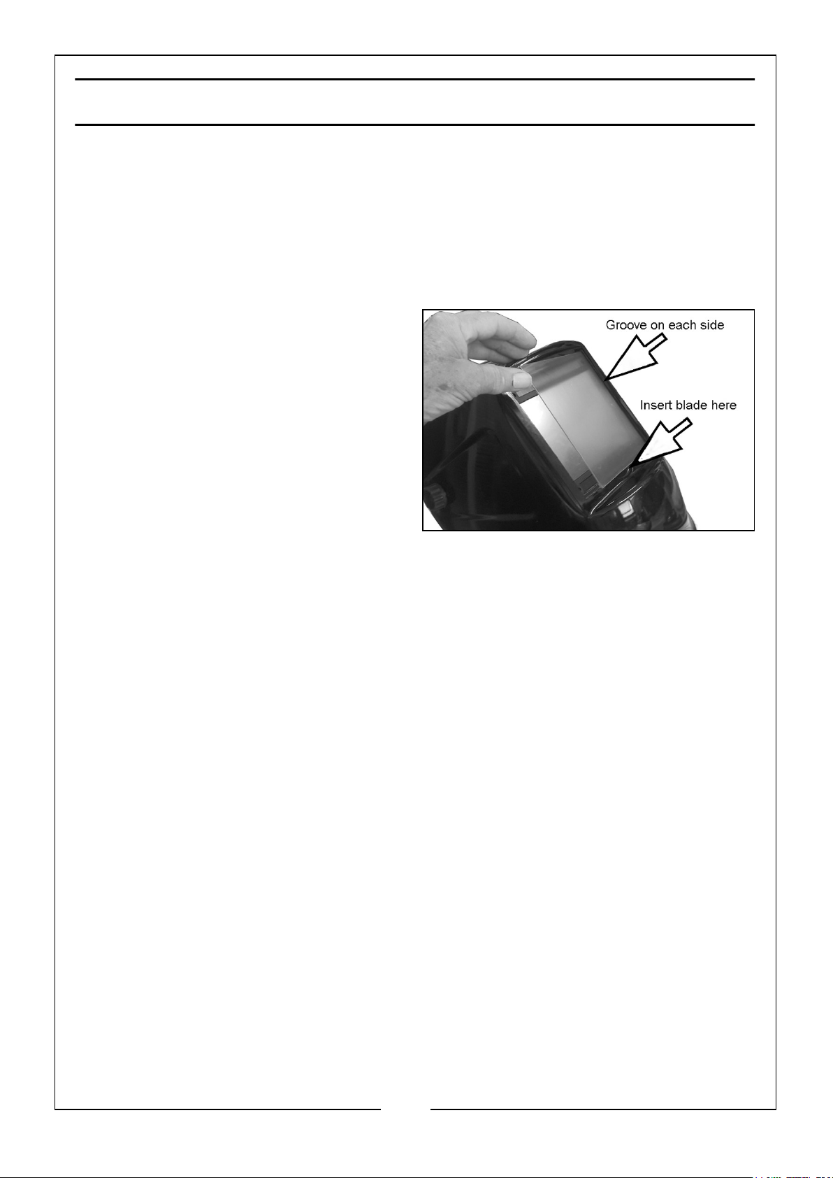
The outer screen can be removed for
replacement and cleaning of the front
lens. It sits in a groove on each side of
the opening and can be prized it out by
carefully inserting a suitable blade into
the slot provided.
The cartridge can be wiped with a
household glass cleaner when dirty.
Apply the cleaner with a clean cloth or
paper towel. DO NOT USE ALCOHOL TO
CLEAN. DO NOT APPLY CLEANER
DIRECTLY TO THE CARTRIDGE.
Clean all lenses with a soft tissue and suitable lens cleaning fluid. DO NOT use
solvents. NEVER use tools or other sharp objects to remove material from the lens or
screen. This may cause damage which may cause incorrect function and invalidate
the warranty. Store the unit in it’s box or similar safe place.
The outer lens cover can be removed for replacement if damaged and may need
replacing regularly.
• Two replacement outer lens covers are supplied with the headshield.
The inner lens cover may also require cleaning. Lift and slide the inside lens cover (on
the operators side of the filter cartridge) free from the filter cartridge.
• A single replacement is supplied with this headshield.
Clean the filter surface, sensors and solar cells regularly by wiping with a household
glass cleaner. Apply the cleaner with a clean cloth or paper towel. DO NOT USE
ALCOHOL TO CLEAN. DO NOT APPLY CLEANER DIRECTLY TO THE CARTRIDGE.
Clean the headshield shell and sweat bands with detergent if necessary.
7
Parts & Service: 020 8988 7400 / E-mail: [email protected] or [email protected]
Page 8
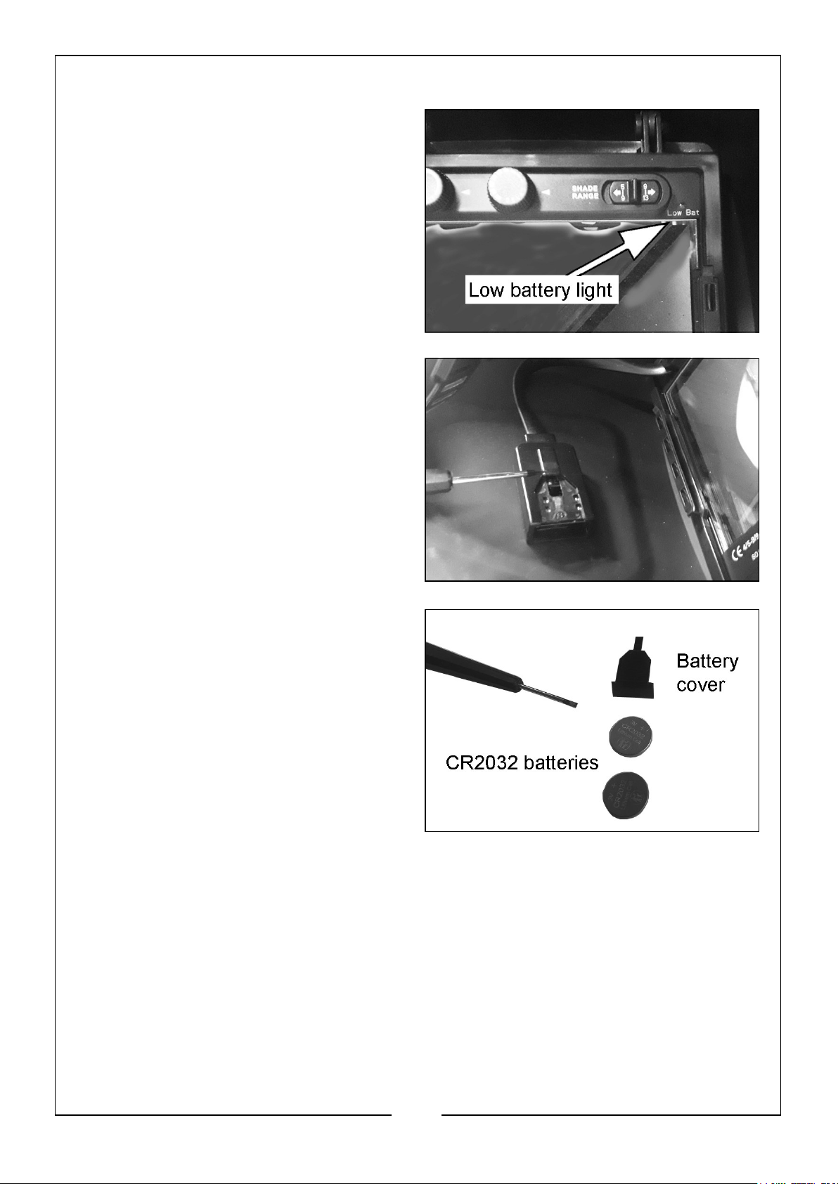
BATTERY REPLACEMENT
The batteries should last approximately
5000 hours of normal use. If the LOW
BATTERY lamp comes on, the battery
should be replaced.
Prise and slide the cover from the battery
storage compartment.
• A small screwdriver blade will be
required to remove the cover and
a pair of tweezers to extract the
batteries.
• 2 x CR2032 batteries are required.
8
Parts & Service: 020 8988 7400 / E-mail: [email protected] or [email protected]
Page 9
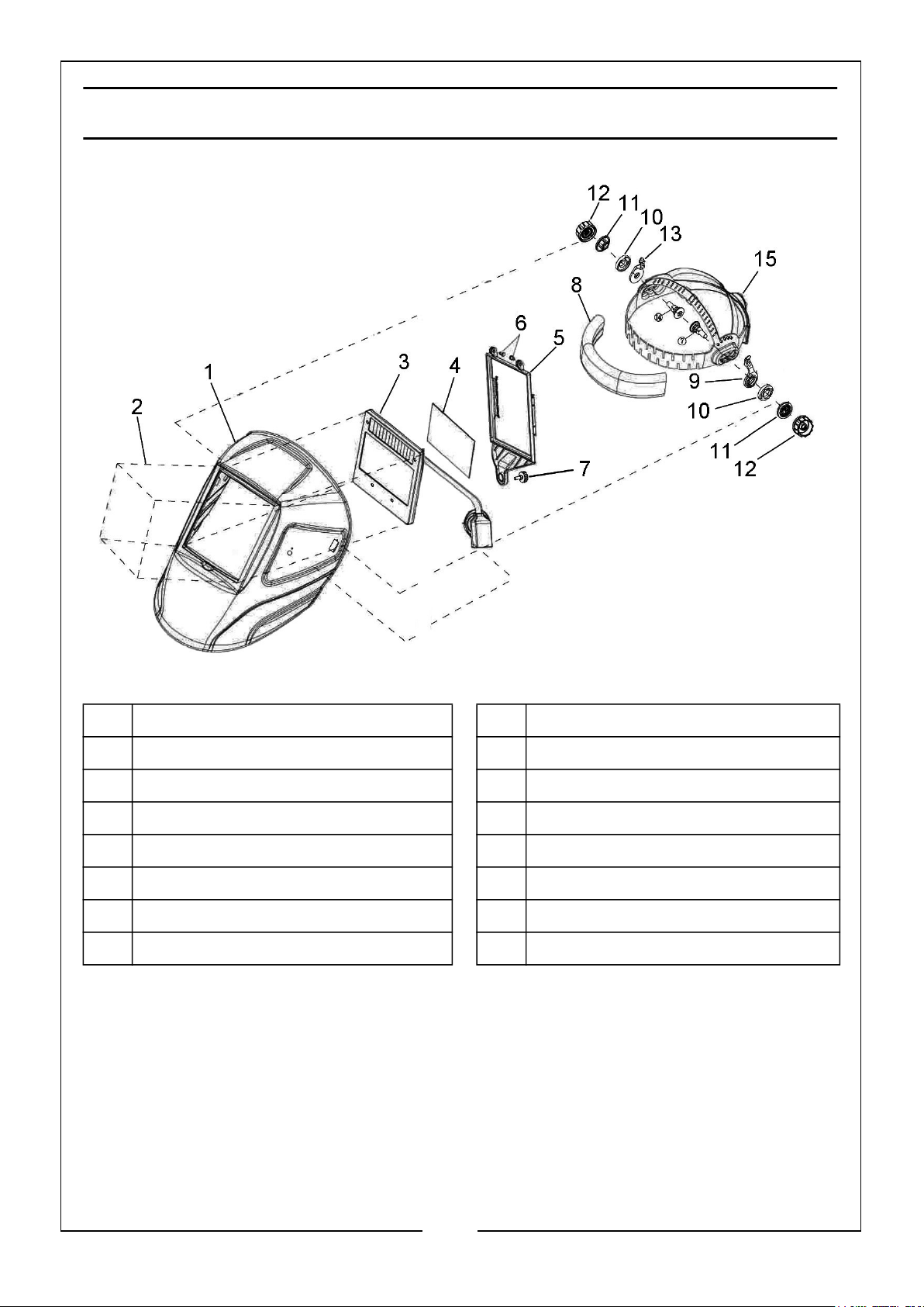
COMPONENT PARTS
1 Shell 9 Lefthand Tab Washer
2 Front Cover Lens 10 Angle Adjustable Washer
3 Auto-Darkening Filter 11 Washer
4. Inside Cover Lens 12 Adjusting Nut
5 Frame 13 Righthand Tab Washer
6 Nuts 14 Screw
7 Thumbscrew 15 Adjustable Headband
8 Sweatband
The GWH8 is supplied with the following;
• Small inner lens cover
• 2x Large outer lens covers
9
Parts & Service: 020 8988 7400 / E-mail: [email protected] or [email protected]
Page 10
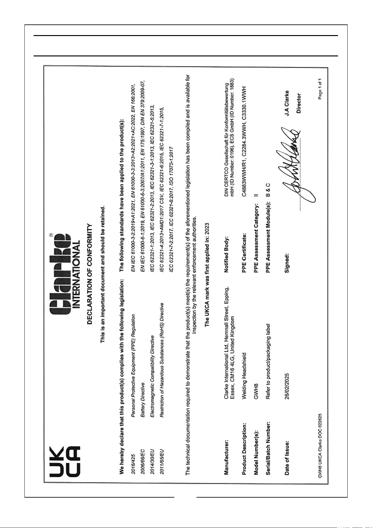
DECLARATION OF CONFORMITY -UK
10
Parts & Service: 020 8988 7400 / E-mail: [email protected] or [email protected]
Page 11
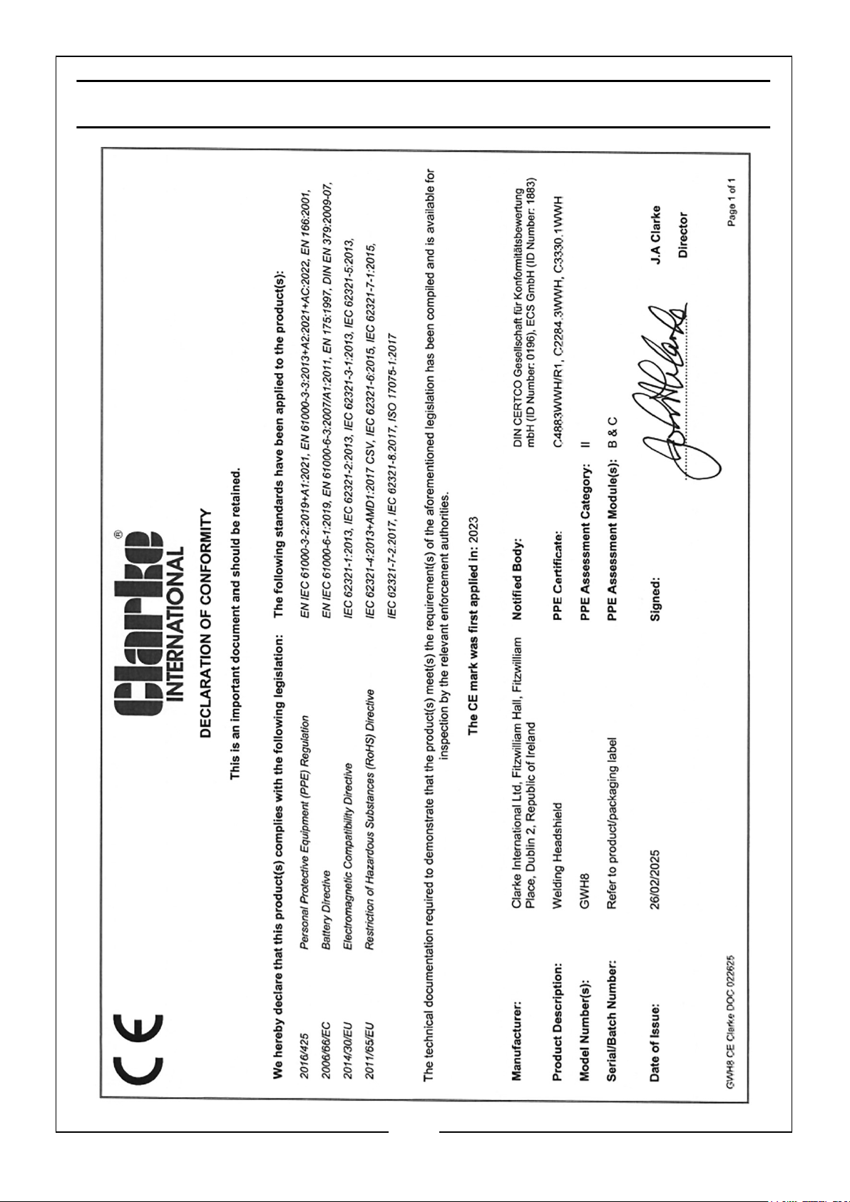
DECLARATION OF CONFORMITY - CE
11
Parts & Service: 020 8988 7400 / E-mail: [email protected] or [email protected]
Page 12

 Loading...