

Page 1
This product conforms with regulation EN131
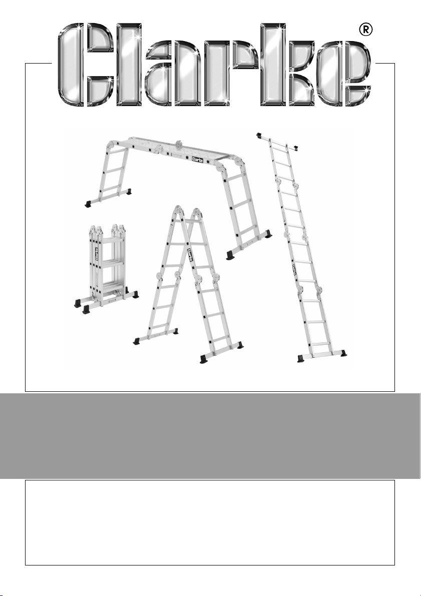
10 IN 1 MULTI-FUNCTION ALUMINIUM
LADDER
MODEL NO: FPL3
PART NO: 3500218
OPERATION & MAINTENANCE
INSTRUCTIONS
LS1218 - ISS5
Page 2
INTRODUCTION
Thank you for purchasing this CLARKE product.
Before attempting to use this product, please read this manual thoroughly and
follow the instructions carefully. In doing so you will ensure the safety of yourself
and that of others around you, and you can look forward to your purchase
giving you long and satisfactory service.
GUARANTEE
This product is guaranteed against faulty manufacture for a period of 12
months from the date of purchase. Please keep your receipt which will be
required as proof of purchase.
This guarantee is invalid if the product is found to have been abused or
tampered with in any way, or not used for the purpose for which it was
intended.
Faulty goods should be returned to their place of purchase, no product can
be returned to us without prior permission.
This guarantee does not effect your statutory rights.
SPECIFICATION
Straight Ladder Height 3400 mm
Step Ladder Height (Top Rung) 1530 mm
Platform Working Height 890 mm
Stabiliser Width 770 mm
Max Load 150 kg
Folded Dimensions (Including Stabiliser) 970 x 770 x 260 mm
Weight 12.3 kg
2
Parts & Service: 020 8988 7400 / E-mail: [email protected] or [email protected]
Page 3
SAFETY SYMBOLS
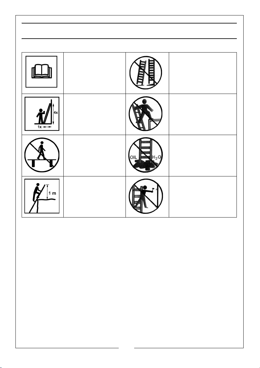
Read instruction
manual before use
Angle the ladder
correctly
Do not use the
ladder as a bridge
Allow 1m of ladder
above the landing
point
Erect the ladder on a
level base
Do not step off of the
side of the ladder
Ensure the ground is
free from
contaminants
Do not over reach
3
Parts & Service: 020 8988 7400 / E-mail: [email protected] or [email protected]
Page 4

LADDER SAFETY
• DON’T exceed the maximum load, this ladder is built for maximum load
of 150 kg.
• DON’T be tempted to use a ladder if you are not fit enough, or suffer
from giddiness or aren’t confident with heights.
• DON’T stand on the top three rungs.
• Don’t overreach; user should keep their belt buckle (navel) inside the
stiles and both feet on the same step/rung throughout the task. Move
the ladder and re-secure it whenever necessary.
• DON’T use the ladder if the rubber feet/plastic end caps are missing.
• DON’T carry heavy items or long lengths of material up a ladder.
• DON’T use a ladder in strong winds or near any power lines.
• DON’T allow any child under 16 to use a ladder.
• DON’T step off a ladder at a high level.
• DON’T use the ladder outside in adverse weather conditions.
• DON’T spend long periods on a ladder without regular breaks (tiredness
is a risk).
• DO extend the ladder at least 1 m above the landing point;
• DO remember that their safest angle of use comes when every 1
measure out from the wall is matched by 4 measures up it. Remember
the rule: ‘ONE OUT FOR FOUR UP’.
• DO try to keep both hands free to hold the ladder as much as possible
while you are climbing or descending - if you need to carry any tools,
use a shoulder bag, belt holster or belt hooks.
• DO hold onto the ladder with one hand while you work. You can get
special trays which fit between the stiles to take paint pots, tools etc.
• DO make sure a door is locked, blocked or guarded by someone if you
are up a ladder in front of it.
• DO familiarise yourself with the operation of the hinges and locks.
• DO keep a secure grip on the ladder when ascending and descending.
• DO wear suitable footwear when climbing a ladder.
• DO avoid work that imposes a sideways loading, such as side-on drilling
through solid materials (e.g. brick or concrete).
4
Parts & Service: 020 8988 7400 / E-mail: [email protected] or [email protected]
Page 5
LADDER ASSEMBLY
Fig 1a
Fig 1b
Fig 2a
Fig 2b
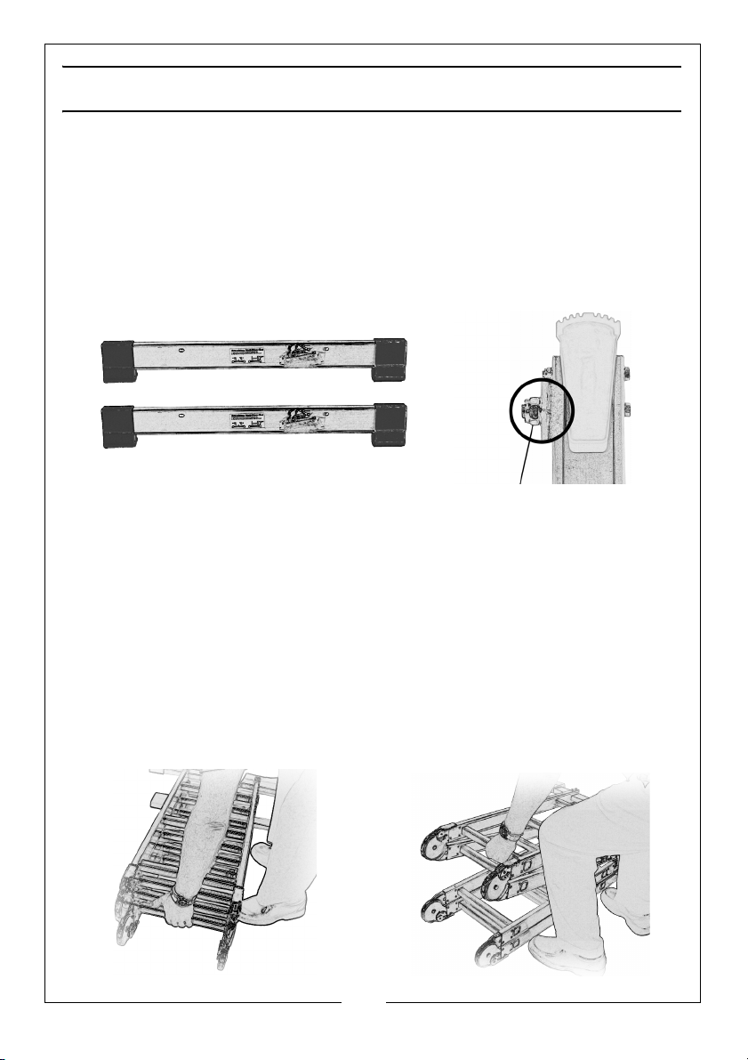
The 2 Stabiliser bars/rubber feet (Fig. 1a) are removed for packing and
transport purposes only, both Stabilisers must be fitted before attempting to
use the ladder.
To assemble the ladder, refer to fitting instruction label on Stabiliser bars. Tools
Required: 1 x 13 mm spanner and 1 x 14 mm spanner.
Loosely fit all bolts allowing the stabiliser to move slightly from side to side,
centralise the stabiliser and tighten locknuts, DO NOT overtighten, (the bolt
thread should just be visible, see Fig. 1b).
NOTE: All bolts must be used to secure stabiliser bars to the ladder (4 in
each stabiliser.
Replacement rubber feet are available from your nearest Clarke dealer. Part
number: JR20001.
HANDLING THE LADDER
Always exercise care when handling the ladder, especially when lifting out of
car boot etc, when the ladder is fully folded, always carry the ladder by lifting
from the bottom Fig. 2a,
Lifting from the top Fig. 2b, causes the ladder to open, making it almost
impossible to lift.
5
Parts & Service: 020 8988 7400 / E-mail: [email protected] or [email protected]
Page 6

BEFORE USE
1. Visually check the ladder is not damaged and is safe to use at the start of
each working day when the ladder is to be used;
• General condition sound (clean & dry, free from wet paint, oil, mud etc)
•No cracks
• No rungs missing or loose
• Not painted (Ladders should never be painted, as this could hide
dangerous defects from view)
• No stiles damaged or bent (Stiles are the outside uprights on a ladder.)
• No corrosion
• No sharp edges or dents
•No rungs bent
• Footpads are OK
• Any caps/rubber fittings are OK
2. Remove any contamination from the ladder, such as wet paint, mud, oil or
snow.
3. Before using a ladder at work, a risk assessment should be carried out
respecting the legislation in the country of use.
POSITIONING THE LADDER
• When positioning the ladder take into account risk of collision with the
ladder e.g. from pedestrians, vehicles or doors. Secure doors (not fire
exists) and windows where possible.
• Ladder should never be repositioned from above.
• Identify any electrical risks in the work area, such as overhead lines or
other exposed electrical equipment.
1. Place the base of the ladder on an even, level surface.
• Ladders should not be positioned on slippery surfaces (such as ice, shiny
surfaces or significantly contaminated solid surfaces) unless additional
effective measures are taken to prevent the ladder slipping such as
tieing the feet of the ladder to stakes in the ground, and placing a large
flat wooden board underneath to help prevent it sinking.
6
Parts & Service: 020 8988 7400 / E-mail: [email protected] or [email protected]
Page 7
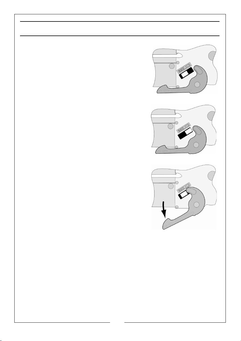
OPENING/LOCKING/UNLOCKING THE LADDER
UNLOCKED
LOCKED
UNLOCKED
To open the ladder into the desired
configuration,
1. Lay the folded ladder on a flat surface,
2. Open one section at a time by pulling open
until a loud click is heard.
• The hinges on that section are now in
locked position, visually check both locks.
• When using the ladder, ALWAYS make a
visual check that ALL hinges have latched
into the locked position.
3. If a section needs to be opened further to
next locking position.
4. Release both locks by pulling the unlocking
levers (one at a time) until the locks latch in
the unlocked position, this section can now
be closed again or opened further to the
next stage, again check both hinges have
locked before use.
5. Repeat above procedure on the other
sections until the desired configuration is
achieved.
7
Parts & Service: 020 8988 7400 / E-mail: [email protected] or [email protected]
Page 8
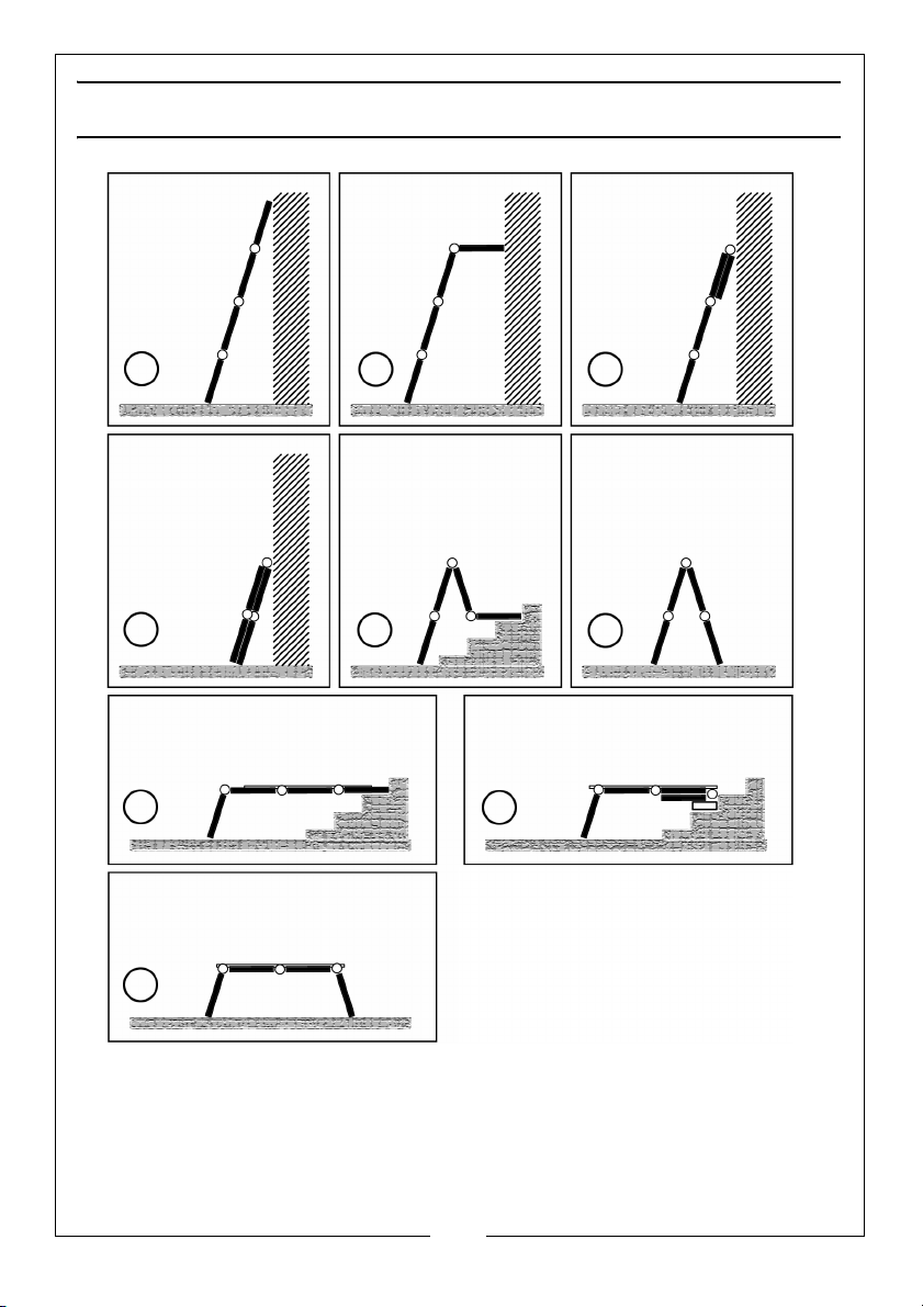
LADDER CONFIGURATIONS
A
B
C
F
H
E
D
G
I
4 Stage Straight
3 Stage Straight
3 Stage Straight
2 Stage Straight
Staircase Step Ladder
Standard Step Ladder
Long Staircase Platform
Short Staircase Platform
Workbench / Platform
Ladder
Ladder
Ladder With
Stand Off
Ladder
IMPORTANT: A deck, part number: 3500216 is available from your nearest Clarke
dealer, for platform configurations G, H, or I. Under no circumstances must the
ladder be used as a platform without the deck, this is a safety requirement, and
must be adhered to at all times.
Parts & Service: 020 8988 7400 / E-mail: [email protected] or [email protected]
8
Page 9
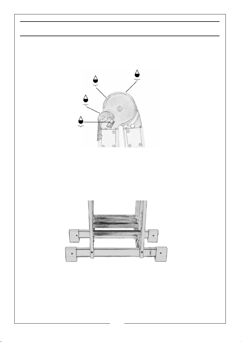
CARE AND MAINTENANCE
Other than keeping your ladder clean and damage free, all that is required is
to periodically apply a spot of light machine oil to the hinges/locks as shown
below, do not flood with oil, any excess oil must be wiped off immediately.
Stabiliser bars can be removed for transport and storage purposes only. This is
done by removing the securing nuts bolts and washers, if removed often,
consideration must be given to replacing the nuts as these are nyloc and will
lose their locking ability.
9
Parts & Service: 020 8988 7400 / E-mail: [email protected] or [email protected]
Page 10

Page 11

Page 12

 Loading...